Non-volatile spin transport in a single domain multiferroic
Antiferromagnets have attracted significant attention in the field of magnonics, as promising candidates for ultralow-energy carriers for information transfer for future computing. The role of crystalline orientation distribution on magnon transport has received very little attention. In multiferroics such as BiFeO3 the coupling between antiferromagnetic and polar order imposes yet another boundary condition on spin transport. Thus, understanding the fundamentals of spin transport in such systems requires a single domain, a single crystal. We show that through Lanthanum(La) substitution, a single ferroelectric domain can be engineered with a stable, single-variant spin cycloid, controllable by an electric field. The spin transport in such a single domain displays a strong anisotropy, arising from the underlying spin cycloid lattice. Our work shows a pathway to understand the fundamental origins of spin transport in such a single domain multiferroic.
Electromagnetic coupling offers a foundational framework for transforming between magnetic and electric fields, primarily facilitated by the principle of magnetic induction through electric currents1; 2. For applications such as manipulating the magnetization of nanoscale magnets in integrated memory and logic, however, the conventional Oersted field approach has been proven to be energy-inefficient and impractical 3. To address the imperative of low-energy consumption in nonvolatile magnetic memory and logic, a promising new avenue has emerged — direct voltage control of magnetism 4; 5; 6; 7; 8; 9. Recent proposals use the magnetoelectric coupling inherent in some multiferroics, which allows for direct electric field control of the magnetic state in such a material10; 7. A notable example of this innovation is the magneto-electric spin-orbit (MESO) device structure, proposed as an inherently non-volatile substitute for complementary metal–oxide–semiconductor (CMOS) devices in integrated logic-in-memory applications 11; 12. To this end, BiFeO3,possessing strong antiferromagnetic magnetoelectric coupling 10; 13; 14, is considered a desirable material for MESO-type devices. Additionally, due to antiferromagnetic character, the materials is robust against external magnetic fields and possesses potentially faster-switching dynamics than ferromagnets. Recently, it has also been shown to be an efficient system for demonstrating switchable magnon spin currents 15; 16. This electric field switchable electro-magnon coupling allows for a simplified version of the MESO device i.e., the antiferromagnetic state is directly read out using the spin-orbit metal in direct contact with the AFM layer, i.e., without an interleaving ferromagnetic layer. The open question remains: How can we uncover methods to improve performance magnitude and deepen our understanding of spin transport in magnetoelectric multiferroics such as BiFeO3? Addressing these questions has the potential to unlock the application-oriented significance of these materials for broader future problems.
The ground state of bulk BiFeO3 has a large polarization (90 C/cm2) along (pc: pseudocubic) and exhibits a canted G-type antiferromagnetism modulated by a spin cycloid (period 65 nm due to the inverse spin current effect17) below the Néel temperature (640K). BiFeO3 features two principal DMI-like interactions, linked to the polarization and the antiferrodistortive octahedral tilts 18, where the tilts and polarization are strongly coupled 19; 20; 21. The octahedral tilt induces a weak magnetic perturbation, and corresponding spin density wave, on top of the antiferromagnetic cycloid of BiFeO318; 21. This can be imaged directly using scanning Nitrogen-vacancy (NV) magnetometry22. To introduce tunability in multiferroic properties, rare earth substitution has shown great potential. Often, in these systems, the ferroelectric polarization moves away from (hereafter all directions are used in the pseudocubic notation unless otherwise specified) 23; 24 intoducing competition between ferroelectric and antiferroelectric phases24; 25; 26; 27; 28. This may allow for additional switching pathways compared to the parent compound BiFeO3, leading to the possibility for new ferroelectric domain configrations. Understanding the formation of a single-domain multiferroic and its potential as a model system for efficient spin magnon transport is the focus of this work.
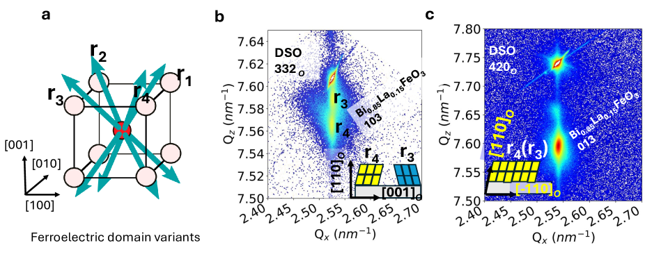
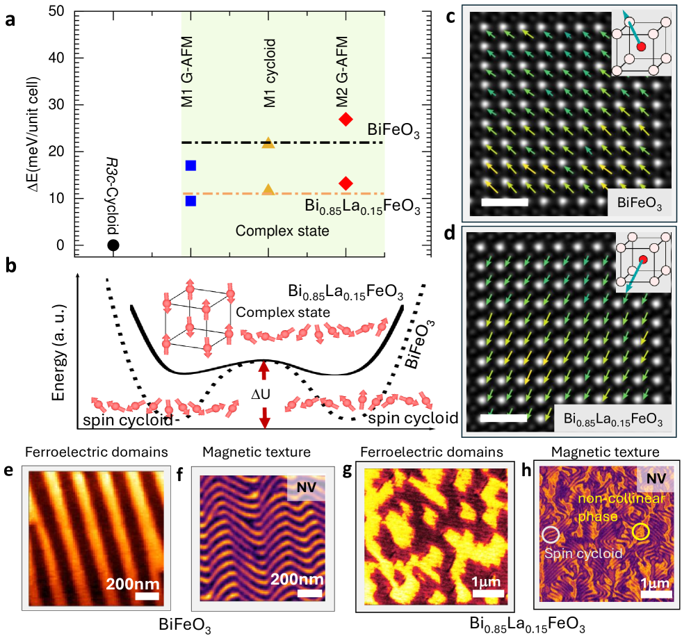
Theoretical calculations predict a cycloidal magnetic ground state in BiFeO3, illustrated in Figure 1a. La-substitution modifies the structure and impacts both the magnitude and direction of the spontaneous polarization significantly, which is observed to be along and is 50 smaller than BiFeO3 . This agrees with experimental values and is supported by high-resolution polar maps (Figure 1a,b, Supplementary Note 2). The reduction in spontaneous polarization is accompanied by a corresponding reduction in the polarization dependent DMI interaction strength 29 and thus the cycloid becomes less energetically stable. In other words, reducing enhances the tilting, and consequently, the tilt-induced-canting of the magnetization becomes larger. These findings confirm that La-substitution modifies the energy landscape for both the ferroelectric and antiferromagnetic states in BiFeO3 (Figure 1 b). In the case of pure BiFeO3, the polar structure is and the cycloid is a stable magnetic state. Interestingly, with the 15 lanthanum substitution (Methods), the uniform canted moment state ( and , Methods) becomes closer in energy to the cycloid state (Figure 1a).
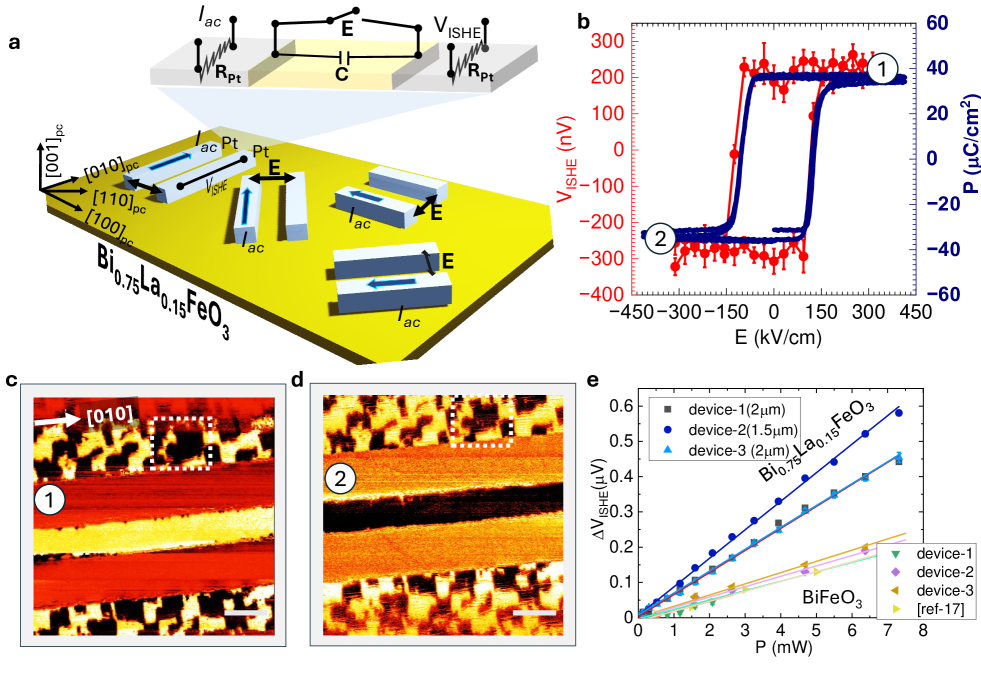
In this spirit, Bi0.85La0.15FeO3 films have been deposited on (O: orthorhombic) DyScO3 substrates (Methods)(Extended Data Fig. 1, and Supplementary Note 1, 2). Using piezo-force microscopy (PFM) and NV magnetometry, as predicted (Figure 1 a-b), the pure cycloid (within 71 ferroelectric BiFeO3) and mixed state of cycloid+G-type antiferromagnet (in blocky-mixed ferroelectric Bi0.85La0.15FeO3) are both observed in a mixed equilibrium state (Figure 1 e-h). To then understand the effect of electric field on the as-grown ferroelectric domain structure, and therefore the ferroelectric polarization, in-plane capacitors were fabricated by optical lithography (ex-situ sputtered platinum (Pt) wires 120m 1.3m 15nm, with 2m spacing and resistivity of 20 cm). The devices were patterned along four different angles in which the long-axis of Pt electrode pairs are parallel to the substrate , , , and pseudocubic directions (Figure 2 a). To visualize the ferroelectric domain reversal across the in-plane devices (Figure 2 b, vs hysteresis), PFM images were recorded after poling in two opposite electric field directions (Fig. 2(c) and (d) and Fig. 3). For a field applied along the direction, in-plane poling leads to the formation of a single ferroelectric domain, which is the novel feature of Bi0.85La0.15FeO3. This has a powerful impact on the magnetic cycloid, which is particularly important for spin transport (discussed later). The formation of a single ferroelectric domain is further verified by rotating the device and performing PFM imaging (Supplementary Note 3), which shows the uniform domain contrast indicative of a single ferroelectric domain. Previously, monodomain features were realized through a non-trivial approach in BiFeO3 using a scanning probe-tip-based method in slow scan mode to physically write a monodomain using a localized in-plane electric field from the tip 22; 32, requiring time and an extremely careful experimental protocol 33; 34, compared to the direct voltage pulse induced switching of La substituted BiFeO3 single domain that we have adopted in this work.
In the case of Bi0.85La0.15FeO3, the polarization is deterministically switched by an electric field at the macroscopic scale of hundreds of microns (see Extended Data Figure 3). A key result of this study is the fact that switching the polarization state with a single, in-plane pulse leads to the deterministic switching and formation of a single multiferroic domain (details in Supplementary Notes 3-5). However, for a field applied along the direction, that is, Pt wires parallel to , a blocky multidomain case persists even in the poled region (Supplementary Figure 6-8). In this multidomain case, upon poling, the domains are locally switched (Supplementary Figure 8), where the domain wall boundaries (or antiphase boundaries, Supplementary Figure 9) do not move. This asymmetric behavior can be attributed to the anisotropic strain from the substrate (Supplementary Note 1), preventing the formation of a macroscopic domain in the device . In devices with electrodes parallel to and , a single ferroelectric domain is formed which can be expected since a component of the electric field points along , allowing the antiphase boundaries to nucleate and move with the field. We can now use such a single domain multiferroic as a model system to understand the stability of the spin cycloid and the corresponding spin transport.
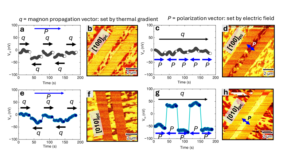
To probe the spin transport, first, an in-plane electric field was applied between the source and detector wires, as indicated in Figure 2a. Following each electrical pulse, a low-frequency (7Hz) alternating current is introduced into the source wire, generating a magnon spin current through the spin Seebeck effect. Subsequently, a non-equilibrium magnon spin accumulation at the Bi0.85La0.15FeO3 interface underneath the Pt detector initiates the flow of spin angular momentum into the adjacent Pt. The resulting spin current is then converted into a measurable voltage through the Inverse Spin Hall Effect (ISHE) of Pt (Supplementary Note 6), and the signal is lock-in detected at 2. Each data point is averaged over a duration of 150 seconds. The ferroelectric polarization hysteresis was measured at 5kHz (Methods) and the corresponding ISHE hysteresis was recorded in a remnant state where an electric field was applied only to set the polarization state and removed during the nonlocal voltage (VISHE) measurement. The nonlocal voltage hysteresis precisely reflects the ferroelectric polarization response (Figure 2b, red data), indicating the existence of polarization-controlled magnon transport. Notably, in the devices, the electric field and therefore the polarization has the capacity to control the sign of the magnon spin current flowing through the Bi0.85La0.15FeO3. This nonvolatile electric field magnon switching is illustrated in the extended data Figure 4, where the ferroelectric polarization deterministically controls non-reciprocal magnon transport in the Bi0.85La0.15FeO3.
Similar experiments on BiFeO3 with a stripe domain structure were performed and a comparison is presented in Fig. 2e. The data corresponding to BiFeO3 is also reproduced from Parsonnet et al 35. The data from the different devices corresponds to the 71 BiFeO3 and reported data from Parsonnet et al 35 belongs to the 109 BiFeO3. We find that the Bi0.85La0.15FeO3 has a consistently higher voltage output than the BiFeO3 (by 400 at the equivalent spacing). Furthermore, we find that the magnitude of the electric field required to switch the magnon spin current is indeed significantly smaller (Supplementary Figure 23), consistent with prior studies 26. This doubly confirms the key advantages of single-domain Bi0.85La0.15FeO3 over its parent compound.
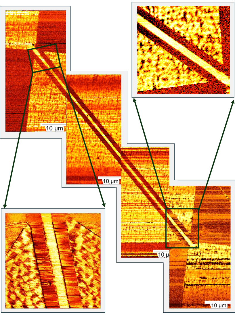
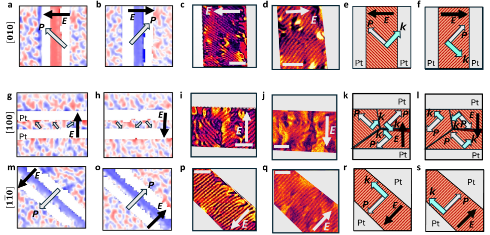
The strong enhancement in the inverse spin Hall voltage for the Bi0.85La0.15FeO3 compared to BiFeO3 prompts us to explore the microscopic differences, if any, in the magnetic structure, particularly the spin cycloid. We used a combination of imaging techniques (PFM and SHG-linear dichroism to probe the ferroelectric state and NV magnetometry to probe the spin cycloid, details in Methods). A comparison of the ferroelectric domain structure and corresponding magnetic (spin cycloid) is presented in Figure 3. To determine the local directions of the polarization in each domain (discussed in Figure 2 c,d), optical SHG is used to map the ferroelectric domains in oppositely poled states (Figure 3 a,b). The red and blue areas correspond to domains with orthogonal in-plane polarization, and it is clear that in the device , the in-plane polarization is switched by 90 upon poling with oppositely directed fields. NV microscopy (Fig. 3c,d) reveals the presence of uniform spin cycloids in oppositely poled domain. It is noteworthy that the sense of the cycloid stripes has rotated by 90 degrees, between these two switched states. This observation reveals that the ferroelectric single domains prefer to form a single variant cycloid, consistent with previous results 22. We can conclude that the polarization is parallel to the spin cycloid stripes, which leads us to conclude that is orthogonal to the propagation vector (drawn schematically in Figure 3e,f ), a result that is consistent with previous works 22; 30; 31. It is also validated by poling the Bi0.85La0.15FeO3 devices at different angles with respect to the direction of the spin cycloid and the ferroelectric polarization. The multi-domain device has two variants of cycloid corresponding to the two ferroelectric domains (Figure 3g-l), whereas the same contrast in (in opposite poling) indicates 180 switching (Figure 3 m-s). Despite the same cycloid in 180 switch, switching will change the handedness in the opposite poled state 36. With these insights, we conclude that the magnetic and ferroelectric order parameters are intimately tied in Bi0.85La0.15FeO3 in a similar fashion to BiFeO3 22; 30, and we show how the polarization and cycloid behave under electric fields pointing in different directions.
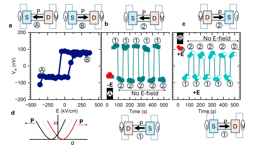
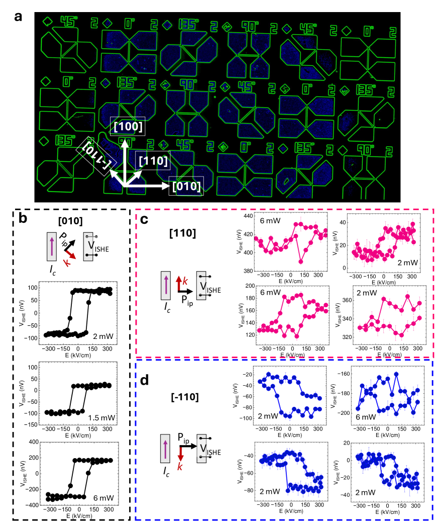
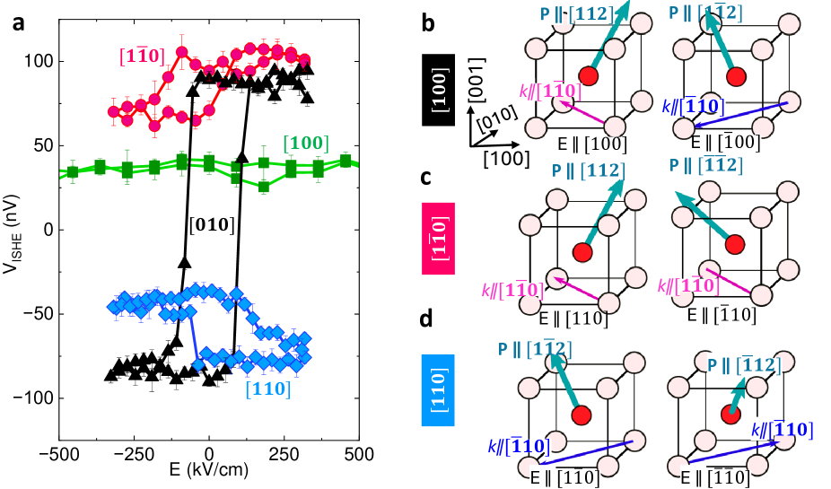
To probe the effect of such a single variant spin cycloid in the single-domain ferroelectric state, we proceeded to measure the non-local spin transport through the same test structures described in Figure 3 a-s, electric field dependent inverse spin Hall voltage hystereses were measured along these crystallographic directions under the same protocol as discussed in Figure 2a,b. The single-domain devices show ISHE voltage hysteresis (in BLACK) that corresponds to their ferroelectric hysteresis (Figure 2b). Strikingly however, the multi-domain oriented device does not show any appreciable ISHE hysteresis (in GREEN) despite exhibiting a clear ferroelectric hysteresis (Supplementary Figure 7). Insight into this is readily obtained from the NV magnetometry images shown in Figure 3 i,j which shows no change in the topology of the spin cycloid; this is also schematically captured in Figure 3 k,l. This reveals that not only is magneto-electric coupling important but also the uniform magnetic texture is required for effective magnon spin flow. The behavior exhibited by the device serves as a key to understanding the device’s behavior. A spin cycloid propagation vector of results in a positive ISHE signal, and yields a negative ISHE signal, as shown in Fig. 4a; it follows that a combination of domains with and , as observed in the device, leads to a null signal without any discernible magnon spin hysteresis. Although the precise correlation between the direction of and the spin carried by a magnon current would be interesting, the present observations affirm that the direction of holds greater significance than the net polarization in determining the non-local magnon signal.
Within the device, illustrated in Figure 4, we note that the () devices have a lower magnitude with a positive (or negative) offset. The sign of the offset is consistent from device to device (5 devices for each orientation), as discussed in Extended Data Figure 5. This can be understood from the symmetry of and , if we consider that La-substitution can allow for different symmetry operations when switching the polarization30; 31. With an electric field along , in the parent BiFeO3, this would result in a C2 rotation about , or two successive 71 switches within the 4b. Here, is also rotated about the , to which it is orthogonal, resulting in . In the case of La-substituted BFO, however, the polarization along may allow for this rotation to happen about the or direction, rather than about the film normal (Figure 4c,d). This operation, for example from to is only a 70 rotation of , rather than the two 71 events to rotate around . Additionally, the rotation axis in this scheme is parallel to , which then does not change sense after the operation. We would expect this to result into a small magnon signal, as observed. This elucidates the anisotropic nature of magnon transport as it is intricately linked to the spin cycloid and thus the polarization of the Bi0.85La0.15FeO3.
In summary, our study demonstrates the effective transmission of magnons in lanthanum-substituted BiFeO3, resulting in a multiferroic material that can be polarized into a stable non-volatile uniform ferroelectric domain with a single variant of the spin cycloid. This stands in contrast to pure BiFeO3, where the coexistence of two variants in both spin cycloids and stripe-like ferroelectric domains leads to a diminishing magnon signal. We observe that – by suitably choosing the direction of the applied electric field – it is possible to maximize or cancel the effect of ferroelectric switching on magnon transport. This research provides a means to customize ferroelectric domains and complex antiferromagnetic spin cycloids, as well as to understand the resulting spin transport, offering a pathway to design the single domain multiferroics for efficient magnon transport for future applications.
Methods
Thin film deposition
BiFeO3 and Lanthanum (La) substituted BiFeO3 (Bi0.85La0.15FeO3) thin films were prepared by pulsed laser deposition (PLD) in an on-axis geometry with a target-to-substrate distance of 50 mm using a KrF excimer laser (wavelength 248 nm, COMPex-Pro, Coherent) on DyScO3 substrates. Film thickness was fixed to 90 nm unless otherwise specified. Before the deposition, the substrates were cleaned with IPA and Acetone for 5 min each. The substrates were attached to a heater using silver paint for good thermal contact.
BiFeO3 and Bi0.85La0.15FeO3 layers were deposited with a laser fluence of 1.8 Jcm-2 under a dynamic oxygen pressure of 140 mTorr at 710 C with a 15 Hz laser pulse repetition rate. The samples were cooled down to room temperature at 30 C/min at a static O2 atmospheric pressure. The prepared samples were immediately transferred to a high vacuum DC magnetron sputtering chamber for Pt deposition. 15 nm of Pt was sputtered at 15W power at room temperature in a 7 mTorr dynamic Ar atmosphere. The thicknesses were calibrated using X-ray reflectivity and atomic force microscopy.
Crystal Structure Determination
The crystal structures of both BiFeO3 and La-substituted BiFeO3 were determined through X-ray diffraction, utilizing a high-resolution X-ray diffractometer (PANalytical, X’Pert MRD). The symmetric line scan (–2) employed a fixed-incident-optics slit set at 1/2, while the reciprocal space mapping (RSM) involved an asymmetric 2D scan with a slit of 1/32. The X-ray source was used the Cu K transition (wavelength: 1.5401 Å), and detection employed a PIXcel3D-Medipix3 detector with a fixed receiving slit of 0.275 mm.
Cross-section Sample Preparation and High-angle Annular Dark Field Scanning Transmission electron microscopy (HAADF-STEM):
The cross-section samples were prepared using a Helios660 scanning electron microscope/focused ion beam (SEM/FIB) with a gallium (Ga) ion beam source. After sample preparation, the cross-section samples were analyzed using an FEI Titan Themis G3 scanning transmission electron microscope (STEM) equipped with double correctors and a monochromator. High-angle annular dark-field scanning transmission electron microscopy (HAADF-STEM) imaging was performed at 300 kV accelerating voltage.
Fourier-filtered HAADF-STEM images were analyzed using CalAtom software to extract the atomic position of Bi/La and Fe ions by multiple-ellipse fitting. The Fe displacement vector in each unit cell was calculated by confirming the center of mass of its four closest Bi/La neighbors. The displacement vector D of the Fe column is represented as follows:
| (1) |
where is the position vector of the Fe column. are the position vectors of the four closest Bi/La neighbors in each unit cell. The color of the displacement vectors was represented by the vector magnitude. The visualization of the two-dimensional atomic displacement was carried out using Python. Calculation of the net displacement according within the unit cell projection is discussed in the supplementary.
Ferroelectric Domain Characteristics
Piezoresponse force microscopy (PFM) imaging was conducted employing the MFP-3D system from Asylum Research, featuring Dual AC Resonance Tracking (DART) mode. Throughout the imaging process, the system operated in lateral mode, ensuring accurate lateral resolution in the acquired images. For these measurements, a silicon cantilever coated with platinum (Pt) was utilized, serving as a conducting electrode for the precise and localized application of an electric field. See Supplementary Note 2 for further information.
Optical second harmonic generation for in-plane polarization mapping (SHG)
These measurements were conducted in a normal-incidence reflection geometry on poled devices. Light excitation was achieved using a Ti/sapphire oscillator with 100 fs pulses, a center wavelength of 900 nm, and a 78 MHz repetition rate. To manipulate the incoming light’s polarization, a Glan–Thompson polarizer was employed, followed by passage through a half-wave plate. The polarized light then traversed a short-pass dichroic mirror and was focused onto the sample using a 100x objective lens with a numerical aperture (NA) of 0.95. The back-reflected SHG signal passed through a short-pass filter and was detected using a spectrometer (SpectraPro 500i, Princeton Instruments) equipped with a charge-coupled device camera (Peltier-cooled CCD, ProEM+:1600 eXcelon3, Princeton Instruments). Diffraction-limited confocal scanning microscopy was employed to generate SHG intensity maps. At the sample location, a commercial Thorlabs polarimeter verified the incoming light’s polarization incident on the sample and the light polarization entering the detector. Linear dichroism maps were constructed through the subtraction of SHG intensity maps with incident light polarization along or directions. The poling process was performed ex-situ for all devices. See Supplementary Note 3 for further information.
Scanning Nitrogen-Vacancy (NV) microscopy
The magnetic texture in the samples was imaged at room temperature utilizing a commercial scanning NV magnetometer (Qnami ProteusQ). Scanning NV magnetometry has been described extensively elsewhere; briefly a parabolically-tapered diamond cantilever (Quantilevel MX+) was used to detect the stray fields from the sample by probing the frequency shift of the NV center spin as the tip was scanned across the surface. To facilitate wide-area scans, data was collected in the ”iso-B” mode, where the peak shift is estimated from the microwave response at two frequencies rather than the full spectrum (e.g., Ref. 37). Iso-B measurements were validated against select measurements of the full spectrum to ensure the magnetic texture is reported faithfully (See Supplementary Note 5)
Device Fabrication
The sample fabrication started with sonication in acetone and isopropyl alcohol. Subsequently, a positive photoresist (MIR 701), approximately 500 nm thick, was uniformly coated at 7000 RPM for 60 seconds using a spin coater. The coated sample was then baked at 100 C for 60 seconds. Photolithography was executed through a Karl Suss MA6 Mask Aligner, with i-line exposure at 10 mW/cm2 for 5 seconds. Following exposure, the resist underwent wet-etching using MEGAPOSIT MF-26A photoresist developer for 20 seconds. Subsequently, the Pt layer was ion-milled down to the multiferroic film surface (Intlvac Nanoquest, with a Hiden Analytical SIMS), resulting in the formation of rectangular stripes measuring 120 m × 1.3 m. This process was conducted at the Marvell Nanofabrication laboratory at UC Berkeley.
Spin Transport Measurements
Transport measurements were conducted employing 4-terminal devices, wherein two terminals were dedicated to source current injection, and the remaining two served as output terminals for inverse spin Hall effect (ISHE) voltage measurement. One source terminal and one detection terminal were also used to apply an electric field for ferroelectric polarization control. The entire experimental setup and procedures were orchestrated using an in-house developed Python code and a Keithley 7001 switch box, maximizing repeatability.
To measure the nonlocal ISHE voltage (), an SR830 lock-in amplifier was synchronized to the second harmonic of the 7Hz source current, isolating responses to the thermal gradients. This comprehensive setup allowed us to perform accurate and controlled transport measurements (using all automated codes), facilitating the investigation of electric field-controlled nonlocal voltage measurements. See Supplementary Note 6 for more information.
Computational Methods (Effective Hamiltonian):
In the case of BiFeO3, the magnetic ground state is a G-type antiferromagnetic configuration, which is modulated by the complex magnetic arrangement called a spin cycloid. The BiFeO3 doped with rare-earth leads to further modulation in the magnetic texture or relaxed into a G-type configuration without the cycloid. To understand this complex state in BiFeO3 and doped BiFeO3 compounds, we performed Monte Carlo simulations governed by the first principle-based effective Hamiltonian. This effective Hamiltonian is expressed as follows for BiFeO3 and doped BFO:
| (2) |
where the first term in equation (2) (FE: ferroelectric, AFD: antiferrodistortion octahedral tilts) contains energy terms arising from the nonmagnetic variables (local mode () being the parameter corresponding to the electric dipole (or the electrical polarization), global homogeneous () and Fe-centred inhomogeneous strain tensor (). is the oxygen octahedral tilt representing the axis of rotation) and their couplings. The second term represents the magnetic mode of the BiFeO3 ( represents the magnetic moment at site centered at the Fe ion with its magnitude fixed (4)) and its couplings with other modes. The expansion of this term is as follows:
| (3) |
Here the Ist term represents the magnetic dipolar interaction. The IInd term corresponds to the magnetic exchange coupling up to the third nearest neighbor. The IIIrd, IVth, and Vth terms describe the change in the magnetic exchange interaction induced by the local polar mode, AFD tilt, and strain. An important point to note is that the first five energy terms lead to the collinear magnetism in BiFeO3. The VIth term involving octahedral or AFD tilting represents the Dzyaloshinskii–Moriya interaction (DMI) and is responsible for the weak magnetization in the AFM state of BiFeO3. The last term of Eq. (4) is responsible for the cycloid (via the inverse spin-current effect which is a DMI effect), and it is the only term related to electric polarization. This energy allows the stable spin cycloid with being the propagation vector along (within (111) plane) (with P ) in BiFeO3.
All the coupling coefficients were calculated using Density Functional Theory for both pure BiFeO3 as well as lanthanum-doped BiFeO3. All the calculations were done for bulk stress-free supercells of unit-cells, both for pure and doped BiFeO3. The complex modulated phases are phases found as a result of temperature cooling of rare-earth-doped BiFeO3, further relaxed for (15) La-substituted BiFeO3 and represent modulated polar arrangements of periods of 6 and 4 unit cells respectively.
DATA AVAILABILITY
The data that support the findings of this study are available from the corresponding author upon reasonable request.
References
- (1) Landau, L. D. L. D. & Lifshitz, E. M. E. M. Electrodynamics of continuous media, by L. D. Landau and E. M. Lifshitz. Translated from the Russian by J. B. Sykes and J. S. Bell. Their Course of theoretical physics, v. 8 (Pergamon Press, Oxford, 1960).
- (2) Folen, V. J., Rado, G. T. & Stalder, E. W. Anisotropy of the magnetoelectric effect in Cr2O3. Phys. Rev. Lett. 6, 607–608 (1961).
- (3) Janesky, J. Freescale Semiconductor: Application note AN3525 Rev. 0, 11/2007 (Jan.2007). Impact of External Magnetic Fields on MRAM Products.
- (4) Chiba, D., Yamanouchi, M., Matsukura, F. & Ohno, H. Electrical manipulation of magnetization reversal in a ferromagnetic semiconductor. Science 301, 943–945 (2003).
- (5) Ohno, H. et al. Electric-field control of ferromagnetism. Nature 408, 944–946 (2000).
- (6) Matsukura, F., Tokura, Y. & Ohno, H. Control of magnetism by electric fields. Nature nanotechnology 10, 209–220 (2015).
- (7) Arima, T.-h. Spin-driven Ferroelectricity and Magneto-Electric Effects in Frustrated Magnetic Systems. Journal of the Physical Society of Japan 80, 052001 (2011). eprint https://doi.org/10.1143/JPSJ.80.052001.
- (8) Fert, A., Ramesh, R., Garcia, V., Casanova, F. & Bibes, M. Electrical control of magnetism by electric field and current-induced torques. Rev. Mod. Phys. 96, 015005 (2024).
- (9) Yuan, W. et al. Electrical switching of the edge current chirality in quantum anomalous Hall insulators. Nature Materials 23, 58–64 (2023).
- (10) Bibes, M. & Barthélémy, A. Towards a magnetoelectric memory. Nature materials 7, 425–426 (2008).
- (11) Manipatruni, S. et al. Scalable energy-efficient magnetoelectric spin–orbit logic. Nature 565, 35–42 (2019).
- (12) Manipatruni, S., Nikonov, D. E. & Young, I. A. Beyond cmos computing with spin and polarization. Nature Physics 14, 338–343 (2018).
- (13) Heron, J. et al. Deterministic switching of ferromagnetism at room temperature using an electric field. Nature 516, 370–373 (2014).
- (14) Chu, Y.-H. et al. Electric-field control of local ferromagnetism using a magnetoelectric multiferroic. Nature materials 7, 478–482 (2008).
- (15) Liao, Y.-C. et al. Understanding the switching mechanisms of the antiferromagnet/ferromagnet heterojunction. Nano Letters 20, 7919–7926 (2020).
- (16) Parsonnet, E. et al. Toward intrinsic ferroelectric switching in multiferroic . Phys. Rev. Lett. 125, 067601 (2020).
- (17) Sosnowska, I., Neumaier, T. P. & Steichele, E. Spiral magnetic ordering in bismuth ferrite. Journal of Physics C: Solid State Physics 15, 4835 (1982).
- (18) Rahmedov, D., Wang, D., Íñiguez, J. & Bellaiche, L. Magnetic cycloid of BiFeO3 from atomistic simulations. Phys. Rev. Lett. 109, 037207 (2012).
- (19) Fedorova, N. S., Nikonov, D. E., Li, H., Young, I. A. & Íñiguez, J. First-principles landau-like potential for and related materials. Phys. Rev. B 106, 165122 (2022).
- (20) Dong, S., Xiang, H. & Dagotto, E. Magnetoelectricity in multiferroics: a theoretical perspective. National Science Review 6, 629–641 (2019).
- (21) Fedorova, N. S. et al. Understanding magnetoelectric switching in thin films. Phys. Rev. B 109, 085116 (2024).
- (22) Gross, I. et al. Real-space imaging of non-collinear antiferromagnetic order with a single-spin magnetometer. Nature 549, 252–256 (2017).
- (23) Kan, D., Anbusathaiah, V. & Takeuchi, I. Chemical substitution-induced ferroelectric polarization rotation in BiFeo3. Advanced Materials 23, 1765–1769 (2011).
- (24) Kan, D. et al. Universal behavior and electric-field-induced structural transition in rare-earth-substituted bifeo3. Advanced Functional Materials 20, 1108–1115 (2010).
- (25) Yadav, A. K. et al. Spatially resolved steady-state negative capacitance. Nature 565, 468–471 (2019).
- (26) Huang, Y.-L. et al. Manipulating magnetoelectric energy landscape in multiferroics. Nature communications 11, 2836 (2020).
- (27) Husain, S. et al. Low-temperature grapho-epitaxial la-substituted BiFeO3 on metallic perovskite. Nature communications 15, 479 (2024).
- (28) Prasad, B. et al. Ultralow voltage manipulation of ferromagnetism. Advanced materials 32, 2001943 (2020).
- (29) Albrecht, D. et al. Ferromagnetism in multiferroic films: A first-principles-based study. Phys. Rev. B 81, 140401 (2010).
- (30) Meisenheimer, P. et al. Switching the spin cycloid in bifeo3 with an electric field. Nature Communications 15, 2903 (2024).
- (31) Meisenheimer, P. et al. Designed spin-texture-lattice to control anisotropic magnon transport in antiferromagnets. arXiv preprint arXiv:2402.12341 (2024).
- (32) Balke, N. et al. Deterministic control of ferroelastic switching in multiferroic materials. Nature nanotechnology 4, 868–875 (2009).
- (33) Matzen, S. et al. Super switching and control of in-plane ferroelectric nanodomains in strained thin films. Nature communications 5, 4415 (2014).
- (34) Cruz, M. P. et al. Strain control of domain-wall stability in epitaxial BiFeO3 (110) films. Phys. Rev. Lett. 99, 217601 (2007).
- (35) Parsonnet, E. et al. Nonvolatile electric field control of thermal magnons in the absence of an applied magnetic field. Phys. Rev. Lett. 129, 087601 (2022).
- (36) Bhattacharjee, S., Rahmedov, D., Wang, D., Íñiguez, J. & Bellaiche, L. Ultrafast switching of the electric polarization and magnetic chirality in BiFeO3 by an electric field. Phys. Rev. Lett. 112, 147601 (2014).
- (37) Tetienne, J.-P. et al. Nanoscale imaging and control of domain-wall hopping with a nitrogen-vacancy center microscope. Science 344, 1366–1369 (2014).
- (38) Chu, Y. et al. Ferroelectric size effects in multiferroic BiFeO3 thin films. Applied Physics Letters 90 (2007).
- (39) Li, Z. et al. Multiferroic skyrmions in BiFeO3. Phys. Rev. Res. 5, 043109 (2023).
Acknowledgements
We thank Sasikanth Manipatruni, and Dmitri E. Nikonov for the fruitful discussions. This work was primarily supported by the U.S. Department of Energy, Office of Science, Office of Basic Energy Sciences, Materials Sciences and Engineering Division under Contract No. DE-AC02-05-CH11231 (Codesign of Ultra-Low-Voltage Beyond CMOS Microelectronics) for the development of materials for low-power microelectronics. H.Z. and R.R. acknowledge the Air Force Office of Scientific Research 2D Materials and Devices Research program through Clarkson Aerospace Corp under Grant No. FA9550-21-1-0460. P.K. acknowledges support from the Intel Corporation as part of the COFEEE program. S.Z. and L.C. acknowledge funding from Brown School of Engineering and Office of the Provost. P.S. acknowledges support from the Massachusetts Technology Collaborative, Award number 22032. L.W.M. and R.R. also acknowledge partial support from the Army/ARL as part of the Collaborative for Hierarchical Agile and Responsive Materials (CHARM) under cooperative agreement W911NF-19-2-0119. X.L. and Y.H. are supported by the Welch Foundation (C-2065-20210327). Y. H. acknowledges the support from NSF-2329111 and NSF-2239545). We acknowledge the Electron Microscopy Center, Rice. J.I.G. acknowledges support from the Luxembourg National Research Fund through grant C21/MS/15799044/FERRODYNAMICS. B.X. acknowledges financial support from the National Natural Science Foundation of China under Grant No. 12074277. S.M. and L.B. would like to acknowledge the ARO Grant No. W911NF-21-1-0113, the U.S. Department of Defense under the DEPSCoR program (Award No. FA9550-23-1-0500) and the Vannevar-Bush Faculty Fellowship (VBFF, Grant No. N00014-20-1-2834). The calculations were performed at the Arkansas High Performance Computing Center (AHPCC).
Author contributions
R.R. and S.H. conceived the idea and designed the experiments. S.H. and I.H. performed sample growth and measurements. I.H. patterned the devices and wrote the experimental procedure scripts. P.M. and P.S. performed the Nitrogen-Vacancy (NV) magnetometry. S.M. performed theoretical calculations under the supervision of B.X., J.I., and L.B. X.L. performed cross-sectional microscopy and polarization mapping under the guidance of Y.H. M.R. did controlled sample preparation under the supervision of D.S. and performed some NV measurements with the help of L.C. P.B. performed second harmonic generation (SHG) mapping. H.T. performed sample lithography under the supervision of J.G.A. J.K., P.K., T.Y.K., and H.Z. gave suggestions on the PFM experiments. S.S. and L.W.M. gave suggestions and commented on the manuscript. R.R. and Z.Y. supervised the work. S.H. and I.H. wrote the manuscript draft. All authors have participated in the discussion and reviewed the manuscript.
Competing interests
The authors declare no competing interests
Extended Data
Extended data for ”Efficient magnon transport in a single domain multiferroic”