⨌
Contact email: sseshad@purdue.edu, wangjie181122@gmail.com††thanks: These authors contributed equally to this work.
Contact email: sseshad@purdue.edu, wangjie181122@gmail.com
Ultrafast dynamic beam steering with optical frequency comb arrays
Abstract
Efficient spatiotemporal control of optical beams is of paramount importance in diverse technological domains. Conventional systems focusing on quasi-static beam control demand precise phase or wavelength tuning for steering. This work presents a time-efficient solution for dynamic beam steering, emphasizing high-duty-cycle operation with fast scan rates, and eliminating the need for active tuning of the beam direction. We achieve 100%-duty-cycle scans at a rate of 9.8 GHz within an angular range of 1∘. Furthermore, leveraging the dispersion characteristics of a virtually imaged phased array (VIPA), we devise a broadband source array that seamlessly transitions from continuous-angular steering to pulsed discrete-angular operation, unlocking possibilities for high-sensitivity angle-, range-, and time-resolved imaging. We also elucidate the adaptability of integrated photonic designs incorporating wavelength-selective switches and spectral dispersers, for enabling a versatile on-chip realization of the proposed beam steering schemes.
Introduction
The significance of optical beam steering is underscored across various cutting-edge technologies, spanning applications including light detection and ranging (LIDAR)[1, 2], free-space communication [3, 4], and virtual/augmented reality displays [5]. Conventional macromechanical scanners are bulky, slow, and lack mechanical durability, while more compact microelectromechanical systems (MEMS) still suffer from vulnerability to the environment with the moving parts, and liquid crystal-based systems are limited by the long response times. Overcoming these limitations is crucial for achieving improved autonomous navigation, enhanced data rates in free-space communication, and increased portability with faster frame rates for display technologies. In this direction, recent years have witnessed a rapid evolution in nanophotonics-based beam steering devices. Chip-scale designs, including optical phased arrays (OPAs) [6, 7, 8], spatial light modulators (SLMs) [9, 10], and active phase gradient metasurfaces [8], have successfully achieved quasi-static beam control by precisely manipulating the light phase from an array of wavelength-scale elements, each independently controlled. Despite these developments, challenges emerge when scaling the elements in the array, leading to the need for intricate control systems for phase tuning and increasing the fabrication complexity.
There have also been efforts exploring wavelength-dependent steering utilizing grating antennas, often integrated with one-dimensional OPA structures to realize two-dimensional steering [11, 12, 13]. Additionally, advancements in beam control dependent on acoustic wavelength have been demonstrated using Brillouin scattering, opening avenues for on-chip frequency-angular resolving LiDAR [14].
While various investigations employ external phase control or wavelength tuning for beam direction scanning, there has been limited progress in the development of schemes for dynamic spatiotemporal beam steering. In our work, we explore dynamic steering schemes with the potential to achieve rapid scan rates without requiring active control of phase or wavelength. Unlike a phase-gradient array requiring active phase tuning to steer the beam, a recent demonstration of a frequency-gradient metasurface [15] introduced time-dependent phase differences between the emitters. This facilitated a continuous and automatic sweep of the beam direction at a periodic rate determined by the frequency increment between the emitters in the array. Despite these advancements, demonstrations so far have achieved a notably low duty cycle for the spatiotemporal scan–that is, the active scanning duration is under 0.5% of the total scan period [15, 16]. This arises due to the spectral disperser’s limited resolution relative to the line-spacing of the optical frequency comb employed. This limitation is also evident in other demonstrations aiming to synthesize quasi-static spatiotemporal beams, where phase and amplitude control is restricted to spatially overlapping groups of comb lines following spectral dispersion [17, 18, 19].
In the first segment of our work, we focus on realizing 100% duty cycle steering thereby enhancing the time efficiency of dynamic beam control. Our methodology centers on achieving a fully resolved frequency-gradient array [Fig 1(B)], accomplished by utilizing the high repetition period of electro-optic (EO) frequency combs and the exceptional spectral resolution of a virtually imaged phased array (VIPA).
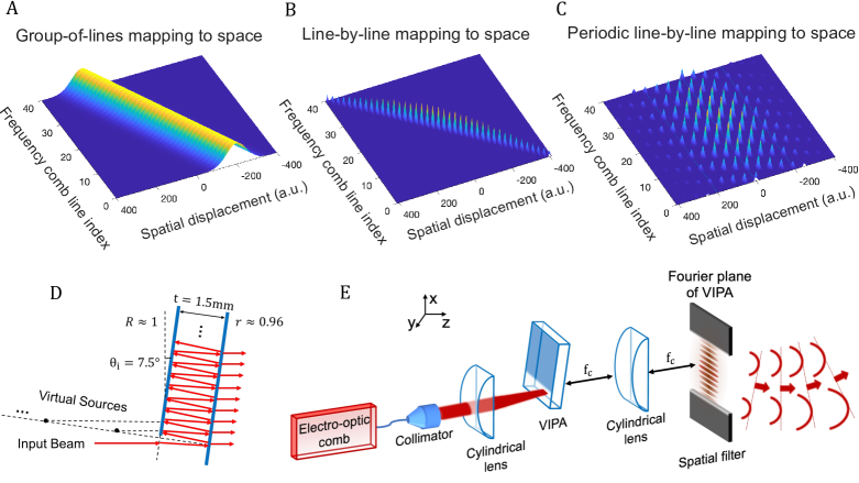
Building upon this foundation, we broaden the scope of our dynamic steering demonstration, transitioning from continuous-angular scanning to pulsed discrete-angular operation by leveraging the periodic spectral dispersion capabilities of the VIPA. We realize a frequency-gradient array composed of coherent optical frequency combs [Fig 1(C)], resulting in the dynamic scanning of broadband pulses. Additionally, we envision the on-chip demonstration of the presented schemes, and propose architectures incorporating full-duty-cycle steering while maximizing the benefits of integrated photonic implementation.
Full-duty-cycle steering
In an OPA, a linear phase gradient is actively adjusted across the emitters to steer the beam. A frequency gradient array introduces a linear, time-dependent phase difference between emitters, resulting in a flat combined wavefront with continuously changing angular orientation over time, realizing dynamic beam steering. If the phase difference between consecutive array elements in an OPA is denoted as , the corresponding time-dependent phase difference in a frequency gradient array with a frequency increment between consecutive elements of is expressed as . The emitted beam direction is given by [15]:
| (1) |
Here, represents the spacing between consecutive emitters, , where is the center frequency of the frequency gradient array, and is the speed of light in the medium. It is important to note that the steering angle varies with time without external control, and the angular steering speed is proportional to the frequency increment .
Previous demonstrations [15, 16] of frequency gradient arrays have illuminated mode-locked laser pulses onto a cascaded system of a diffraction grating and a lens. The grating maps frequencies to angles, and the lens performs a spatial Fourier transform, mapping the angles to space. These steering demonstrations have achieved a limited scan duration of 8 ps in a scan period of 12.5 ns [15], and 81 ps in a scan period of 20 ns [16], falling under a duty cycle of 0.5%. We identify this limitation in the duty cycle of the scan as stemming from a poorly resolved frequency-gradient array composed of a group of comb lines mapped to each point in space, as illustrated in Fig. 1(a). The repetition rate of the mode-locked laser (below 100 MHz) used in the experiments was considerably lower than the spectral resolution of the diffraction grating (exceeding 10 GHz), which led to the spectral resolution spanning over a group of comb lines. For example, the duty cycle in the prior demonstrations can be explained by nearly 1500 comb lines [15] and 240 comb lines [16] spatially overlapping after spectral dispersion. This results in steered waveforms that are isolated in time, and restricts the active scan time relative to the scan period given by . In our current work, we address this limitation by individually discerning frequency lines in space, as illustrated in Fig. 1(B). Our approach is inspired by previous studies on high-resolution line-by-line Fourier pulse shaping, that achieved shaped-arbitrary waveforms with a full duty cycle via line-by-line spectral-phase and amplitude control of an input frequency comb. The shaped waveforms spanned the entire time-domain repetition period of the frequency comb resulting in high time-bandwidth products [20, 21, 22]. In contrast, traditional group-of-lines pulse shaping generates low-duty cycle waveform [23].
Similarly, line-by-line resolved frequency-to-space mapping of the input frequency comb can result in steering spanning the entire scan period achieving 100% duty cycle. To illustrate this concept, in our experiments, we use an electro-optic (EO) comb as a source, with a repetition rate of approximately 9.8 GHz. This comb is generated through a series of intensity and phase modulations applied to a continuous wave laser, resulting in spectrally-flat, evenly-spaced sidebands around the carrier frequency [24]. Subsequently, the EO comb is directed to a virtually imaged phased array (VIPA), a Fabry-Perot etalon with a side entrance renowned for its high-resolution spectral dispersion capabilities [25, 26]. As illustrated in Figs. 1(D), the VIPA consists of two plane parallel mirrors separated by a glass material. The front mirror exhibits nearly 100% reflectivity, except for a specific window area used to couple light into the device, and the back mirror is partially reflective, typically with over 95% reflectivity. The input beam is focused into the VIPA by a cylindrical lens at an incident angle of . The beam bounces back and forth between the two mirrors, producing multiple reflections on the back mirror of the VIPA. The transmitted beams from the back mirror appear as though they originate from an array of virtual sources spaced from their corresponding reflection spots by the distance traveled by the beam within the VIPA [27]. The linear delay gradient across the transmitted beams generates a frequency-dependent phase difference and induces angular dispersion as the beams diffract and interfere. The VIPA is followed by a cylindrical lens that maps the frequencies from angle to space along the dispersion axis (x-axis) on the back focal plane or the Fourier plane of the VIPA. Additional information regarding the experimental setup and the VIPA’s specifications can be found in [28].
The VIPA surpasses conventional diffraction gratings in angular dispersion, exhibiting significantly enhanced resolving power as the number of virtual sources in the array increases. This characteristic enables VIPAs to achieve sub-GHz resolutions, outperforming regular diffraction gratings by one to two orders of magnitude.
Similar to Fabry-Perot etalons, the VIPA possesses a free-spectral range (FSR) determined by the optical path length between two reflections. In the case of a broadband input, frequencies separated by the VIPA-FSR are directed to the same angle and spatial position on the Fourier plane, as illustrated in Fig. 1(c). This presents a challenge in applications like spectral filtering and pulse shaping, where the total bandwidth can be constrained by the VIPA-FSR (typically within a few hundred GHz), and hence another broadband disperser is often introduced along the orthogonal axis to resolve this ambiguity [29, 30]. On the other hand, in this work we exploit the periodic dispersion feature of the VIPA to our advantage in subsequent experiments, unlocking the capability for discrete-angular dynamic steering.
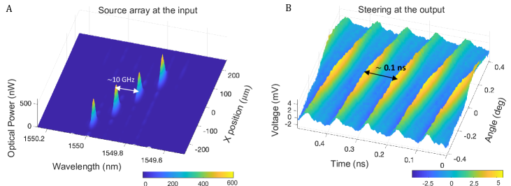
In our experiments, we employ a VIPA with an FSR of 49.2 GHz at an input angle of 7.6∘. The line-spacing of the EO comb is set to 9.8 GHz.A pulse shaper is used to limit the total number of comb lines that are routed into the VIPA to four. A spatial filter in the Fourier plane selects the lowest diffraction order of the VIPA. The frequency spectrum on the Fourier plane is plotted in Fig. 2(A). The selected single diffraction order contains four comb lines spatially separated by 91.8 µm, consequently, the frequency-array is characterized by a linear gradient of MHz/um. We observe that the individual comb lines in the array are discernible in space. The theoretical resolution of the VIPA is expected to be under 1 GHz [26], significantly surpassing the 9.8 GHz-repetition rate of the EO comb.
To emulate the far-field pattern produced by the frequency-gradient array, we employ spatial Fourier transform using a spherical lens following the Fourier plane [28]. The steered beam at the output is coupled into a single-mode fiber, with subsequent detection utilizing a 23 GHz-bandwidth photodetector. The time-domain waveforms are then observed on a sampling scope and plotted as a function of angle in Fig.2(B). The waveforms reveal continuous dynamic steering of the beam over a range of with a scan rate of 9.8 GHz, as dictated by Eq. (1). This demonstration boasts a duty cycle of 100%, a direct outcome of resolving the individual comb lines within the frequency gradient array.
Pulsed beam steering
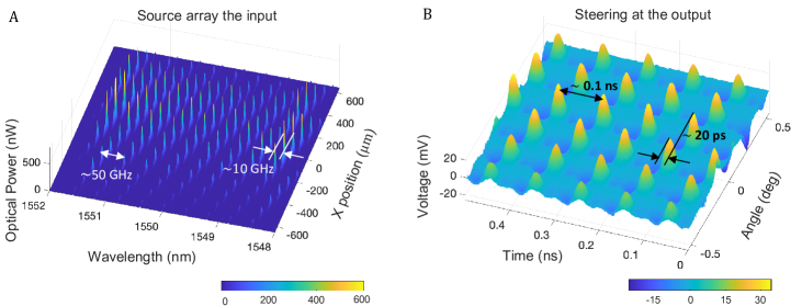
Advancing beyond the continuous steering demonstration, we explore broadband emitters positioned in the Fourier plane of the VIPA designed for pulsed discrete-angular dynamic steering. An EO comb with an FSR of 9.8 GHz is generated featuring a flat spectrum with 50 comb lines within a 10 dB bandwidth. This comb is seeded into the VIPA, which has an FSR of 49.2 GHz. The comb line-spacing is chosen to precisely match an integer fraction of the VIPA FSR, resulting in subsets of comb lines in the Fourier plane of the VIPA as measured and plotted in Fig.3(A). The comb lines periodically superimpose on each other every 49.2 GHz (VIPA-FSR), and the adjacent subsets of comb lines feature an offset frequency shift of 9.8 GHz (comb repetition rate). In the absence of a spatial filter, the spatial distribution of the input comb lines measured in the VIPA’s Fourier plane is plotted in Fig.3(A). The frequency-to-space mapping is fairly linear explained by the dispersion law of VIPA [28]. While periodic dispersion of the VIPA is often perceived as a compromise on the total bandwidth, in our approach, we exploit this characteristic to dynamically scan broadband pulses. The time-domain waveforms measured after the spatial Fourier transform of the VIPA’s Fourier plane is presented in Fig.3(B). The steered pulse train peaks at discrete angles spaced by 0.188∘. The pulses exhibit a period of 1010.2 ps at a fixed angular orientation consistent with the comb repetition rate. In other words, the angular scan rate is determined by the carrier-envelope offset increment of 9.8 GHz between adjacent combs in the Fourier plane of the VIPA. The pulses are delayed by 20.4 0.2 ps between consecutive angular peaks, in line with the FSR of the VIPA. The active scanning time spans the entire scan period, affirming a full-duty-cycle operation. The theoretical prediction in close agreement with the experiment is detailed in the supplementary text S1. Note that the angular scanning observed here can also be understood on the basis of the fundamental relationship between spectral dispersion and transverse delay-gradient across the spatial aperture [23, 31].
Potential for on-chip implementation
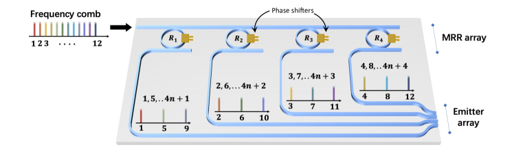
We outline a design for an integrated photonic implementation for achieving both continuous and discrete angular dynamic beam steering with a full-duty cycle. The frequency-gradient array can be realized using microring filter arrays by leveraging their resolution at a single GHz-level or lower. An illustration of the design is shown in Fig. 4 where microring resonators (MRRs) with nearly identical free-spectral range are serially coupled to a bus waveguide. Similar designs with higher-order MRR filters have been explored to realize on-chip wavelength selective switches using silicon photonics technology [32]. An EO frequency comb is seeded to the bus waveguide with its repetition rate chosen to be an integer fraction of the microring’s FSR. Fig. 4 illustrates an example where MRR-FSR is four times the line-spacing of the input frequency comb. Through tuning of MRR resonances using thermo-optic phase-shifters, the resonance spacing between consecutive MRRs is set to the input comb’s line-spacing, facilitating the selection of a subset of input comb lines at the drop ports of the MRRs, referred to as sub-combs hereafter. These sub-combs exhibit a repetition rate matching the MRR-FSR, and they are linearly frequency-shifted by the input comb’s line-spacing. The resulting frequency-gradient array of sub-combs is then directed to an array of edge emitters, enabling dynamic steering in the far field.
Similar to OPA systems, the total number of emitters and their spacing dictates the beam width and the field-of-view. The quality factor and resonance linewidth of the MRR can be chosen to accommodate differences in the FSRs of the MRRs due to fabrication imperfections. The cumulative path lengths traversed by each subcomb through the bus waveguide, MRR, and drop ports are matched (to well within the pulse duration) enabling time-synchronized emission of the pulses. Notably, this design can be applied to both continuous and pulsed dynamic scan scenarios by appropriately adjusting the input pump bandwidth.
An alternative on-chip realization involves using a spectral disperser, such as the Arrayed Waveguide Grating (AWG) [33, 34]. The AWG produces periodic dispersion at its output, which can be employed for beam steering, akin to our experiments with a VIPA. Recent advancements in AWG design have showcased enhanced spectral resolution at the GHz-scale [35, 36, 37, 38]. Both the MRR-based and AWG-based implementation approaches eliminate the need for real-time phase tuning to control the output beam orientation. However, the MRR-based approach stands out by featuring notably narrow linewidths and reconfigurable resonances, providing the capability to adapt to different scan rates using a single device.
Summary and conclusions
This work illustrates how to realize time-efficient dynamic scanning that achieves a 100%-duty cycle by resolving individual lines in the frequency-gradient source array. By further leveraging the operational characteristics of the VIPA, we have presented a design for a broadband source array capable of achieving dynamic pulsed beam steering. Our demonstration achieves scanning in discrete steps of 0.188∘ and 20.4 ps in the angular and temporal domains, respectively.
We explore on-chip implementations for dynamic steering schemes that can harness the merits of integrated photonic technology, including miniaturization, wide field-of-view operation, and high spatial resolution. Notably, the presented techniques eliminate the need for real-time tuning of phase, delay, or wavelength to steer the beam. This work opens avenues for versatile dynamic beam control with the potential for comprehensive angle, range, and time-resolved imaging.
References
- Lin et al. [2022] S. Lin, Y. Chen, and Z. J. Wong, High-performance optical beam steering with nanophotonics, Nanophotonics 11, 2617 (2022).
- Kim et al. [2021] I. Kim, R. J. Martins, J. Jang, T. Badloe, S. Khadir, H.-Y. Jung, H. Kim, J. Kim, P. Genevet, and J. Rho, Nanophotonics for light detection and ranging technology, Nature nanotechnology 16, 508 (2021).
- Poulton et al. [2019] C. V. Poulton, M. J. Byrd, P. Russo, E. Timurdogan, M. Khandaker, D. Vermeulen, and M. R. Watts, Long-range lidar and free-space data communication with high-performance optical phased arrays, IEEE Journal of Selected Topics in Quantum Electronics 25, 1 (2019).
- Polkoo and Renshaw [2019] S. S. Polkoo and C. K. Renshaw, Imaging-based beam steering for free-space optical communication, Applied optics 58, D12 (2019).
- Chen et al. [2016] H. Chen, Y. Weng, D. Xu, N. V. Tabiryan, and S.-T. Wu, Beam steering for virtual/augmented reality displays with a cycloidal diffractive waveplate, Optics express 24, 7287 (2016).
- Guo et al. [2021] Y. Guo, Y. Guo, C. Li, H. Zhang, X. Zhou, and L. Zhang, Integrated optical phased arrays for beam forming and steering, Applied Sciences 11, 4017 (2021).
- Heck [2017] M. J. Heck, Highly integrated optical phased arrays: photonic integrated circuits for optical beam shaping and beam steering, Nanophotonics 6, 93 (2017).
- Berini [2022] P. Berini, Optical beam steering using tunable metasurfaces, ACS Photonics 9, 2204 (2022).
- Li et al. [2019] S.-Q. Li, X. Xu, R. Maruthiyodan Veetil, V. Valuckas, R. Paniagua-Domínguez, and A. I. Kuznetsov, Phase-only transmissive spatial light modulator based on tunable dielectric metasurface, Science 364, 1087 (2019).
- Panuski et al. [2022] C. L. Panuski, I. Christen, M. Minkov, C. J. Brabec, S. Trajtenberg-Mills, A. D. Griffiths, J. J. McKendry, G. L. Leake, D. J. Coleman, C. Tran, et al., A full degree-of-freedom spatiotemporal light modulator, Nature Photonics 16, 834 (2022).
- Van Acoleyen et al. [2009] K. Van Acoleyen, W. Bogaerts, J. Jágerská, N. Le Thomas, R. Houdré, and R. Baets, Off-chip beam steering with a one-dimensional optical phased array on silicon-on-insulator, Optics letters 34, 1477 (2009).
- Xiao et al. [2005a] F. Xiao, W. Hu, and A. Xu, Optical phased-array beam steering controlled by wavelength, Applied optics 44, 5429 (2005a).
- Im et al. [2020] C.-S. Im, B. Bhandari, K.-P. Lee, S.-M. Kim, M.-C. Oh, and S.-S. Lee, Silicon nitride optical phased array based on a grating antenna enabling wavelength-tuned beam steering, Optics express 28, 3270 (2020).
- Li et al. [2023a] B. Li, Q. Lin, and M. Li, Frequency–angular resolving lidar using chip-scale acousto-optic beam steering, Nature 620, 316 (2023a).
- Shaltout et al. [2019] A. M. Shaltout, K. G. Lagoudakis, J. van de Groep, S. J. Kim, J. Vučković, V. M. Shalaev, and M. L. Brongersma, Spatiotemporal light control with frequency-gradient metasurfaces, Science 365, 374 (2019).
- Li et al. [2023b] Y. Li, X. Geng, X. Kong, X. Liu, Z. Liu, Z. Wang, D. Liang, Q. Xie, J. Xie, L. Deng, et al., Picosecond wide-angle dynamic beam steering for object tracking, Laser & Photonics Reviews 17, 2200274 (2023b).
- Chen et al. [2022] L. Chen, W. Zhu, P. Huo, J. Song, H. J. Lezec, T. Xu, and A. Agrawal, Synthesizing ultrafast optical pulses with arbitrary spatiotemporal control, Science Advances 8, eabq8314 (2022).
- Yessenov et al. [2022] M. Yessenov, L. A. Hall, K. L. Schepler, and A. F. Abouraddy, Space-time wave packets, Advances in Optics and Photonics 14, 455 (2022).
- Kondakci and Abouraddy [2017] H. E. Kondakci and A. F. Abouraddy, Diffraction-free space–time light sheets, Nature Photonics 11, 733 (2017).
- Huang et al. [2008] C.-B. Huang, Z. Jiang, D. Leaird, J. Caraquitena, and A. Weiner, Spectral line-by-line shaping for optical and microwave arbitrary waveform generations, Laser & Photonics Reviews 2, 227 (2008).
- Jiang et al. [2005] Z. Jiang, D. Seo, D. E. Leaird, and A. M. Weiner, Spectral line-by-line pulse shaping, Optics letters 30, 1557 (2005).
- Cundiff and Weiner [2010] S. T. Cundiff and A. M. Weiner, Optical arbitrary waveform generation, Nature Photonics 4, 760 (2010).
- Weiner [2000] A. M. Weiner, Femtosecond pulse shaping using spatial light modulators, Review of scientific instruments 71, 1929 (2000).
- Metcalf et al. [2013] A. J. Metcalf, V. Torres-Company, D. E. Leaird, and A. M. Weiner, High-power broadly tunable electrooptic frequency comb generator, IEEE Journal of Selected Topics in Quantum Electronics 19, 231 (2013).
- Xiao et al. [2004] S. Xiao, A. M. Weiner, and C. Lin, A dispersion law for virtually imaged phased-array spectral dispersers based on paraxial wave theory, IEEE journal of quantum electronics 40, 420 (2004).
- Xiao et al. [2005b] S. Xiao, A. M. Weiner, and C. Lin, Experimental and theoretical study of hyperfine wdm demultiplexer performance using the virtually imaged phased-array (vipa), Journal of lightwave technology 23, 1456 (2005b).
- Shirasaki [1996] M. Shirasaki, Large angular dispersion by a virtually imaged phased array and its application to a wavelength demultiplexer, Optics letters 21, 366 (1996).
- [28] Materials and methods are available as supplementary materials.
- Supradeepa et al. [2008] V. Supradeepa, C.-B. Huang, D. E. Leaird, and A. M. Weiner, Femtosecond pulse shaping in two dimensions: Towards higher complexity optical waveforms., Optics express 16, 11878 (2008).
- Lee et al. [2023] D. Lee, T. Nakamura, A. J. Metcalf, N. E. Flowers-Jacobs, A. E. Fox, P. D. Dresselhaus, and F. Quinlan, Sub-ghz resolution line-by-line pulse shaper for driving superconducting circuits, APL Photonics 8 (2023).
- Weiner [2011] A. M. Weiner, Ultrafast optics (John Wiley & Sons, 2011).
- Cohen et al. [2023] L. M. Cohen, S. Fatema, V. V. Wankhade, N. B. Lingaraju, B. Zhang, D. Onural, M. Popovic, and A. M. Weiner, Fine-resolution silicon photonic wavelength-selective switch using hybrid multimode racetrack resonators, arXiv preprint arXiv:2309.17222 (2023).
- Yoshikuni [2002] Y. Yoshikuni, Semiconductor arrayed waveguide gratings for photonic integrated devices, IEEE journal of selected topics in Quantum Electronics 8, 1102 (2002).
- Cheben et al. [2007] P. Cheben, J. Schmid, A. Delâge, A. Densmore, S. Janz, B. Lamontagne, J. Lapointe, E. Post, P. Waldron, and D.-X. Xu, A high-resolution silicon-on-insulator arrayed waveguide grating microspectrometer with sub-micrometer aperture waveguides, Optics express 15, 2299 (2007).
- Gatkine et al. [2017] P. Gatkine, S. Veilleux, Y. Hu, J. Bland-Hawthorn, and M. Dagenais, Arrayed waveguide grating spectrometers for astronomical applications: new results, Optics express 25, 17918 (2017).
- Zhang et al. [2022] Y. Zhang, J. Zhan, S. Veilleux, and M. Dagenais, Arrayed waveguide grating with reusable delay lines (rdl-awg) for high resolving power, highly compact, photonic spectrographs, in 2022 IEEE Photonics Conference (IPC) (IEEE, 2022) pp. 1–2.
- Gatkine et al. [2023] P. Gatkine, N. Jovanovic, G. Sercel, J. Jewell, J. K. Wallace, and D. Mawet, A near-infrared, on-chip astrophotonic spectrograph with a resolving power of 40,000, in 2023 Conference on Lasers and Electro-Optics Europe & European Quantum Electronics Conference (CLEO/Europe-EQEC) (IEEE, 2023) pp. 1–1.
- Stoll et al. [2020] A. Stoll, K. Madhav, and M. Roth, Performance limits of astronomical arrayed waveguide gratings on a silica platform, Optics Express 28, 39354 (2020).
- Lancis et al. [2008] J. Lancis, P. Andrés, et al., Lossless equalization of frequency combs, Optics letters 33, 1822 (2008).
- Supradeepa et al. [2010] V. Supradeepa, C. M. Long, D. E. Leaird, and A. M. Weiner, Self-referenced characterization of optical frequency combs and arbitrary waveforms using a simple, linear, zero-delay implementation of spectral shearing interferometry, Optics Express 18, 18171 (2010).
Acknowledgements
We thank Dr. Jason D. McKinney for valuable discussions and Avanex Corporation for the VIPA devices. Funding: This work was supported by the Air Force Office of Scientific Research grant (FA9550-20-1-0283). Author contributions: S.S. developed the concepts, conducted the theoretical analysis, and assisted in the experiments. J.W. conducted the experiments. A.M.W. developed the concepts and supervised the project. All the authors contributed to and approved the manuscript. Competing interests: The authors declare no other competing interests. Data and materials availability: All data are available in the main text or the supplementary materials.