A Novel Terabit Grid-of-Beam Optical Wireless Multi-User Access Network With Beam Clustering
Abstract
In this paper, we put forward a proof of concept for sixth generation (6G) Terabit infrared (IR) laser-based indoor optical wireless networks. We propose a novel double-tier access point (AP) architecture based on an array of arrays of vertical cavity surface emitting lasers (VCSELs) to provide a seamless grid-of-beam coverage with multi-Gb/s per beam. We present systematic design and thorough analytical modeling of the AP architecture, which are then applied to downlink system modeling using non-imaging angle diversity receivers (ADRs). We propose static beam clustering with coordinated multi-beam joint transmission (CoMB-JT) for network interference management and devise various clustering strategies to address inter-beam interference (IBI) and inter-cluster interference (ICI). Non-orthogonal multiple access (NOMA) and orthogonal frequency division multiple access (OFDMA) schemes are also adopted to handle intra-cluster interference, and the resulting signal-to-interference-plus-noise ratio (SINR) and achievable data rate are derived. The network performance is studied in terms of spatial distributions and statistics of the downlink SINR and data rate through extensive computer simulations. The results demonstrate that data rates up to Gb/s are achieved within the coverage area and a properly devised clustering strikes a balance between the sum rate and fairness depending on the number of users.
Index Terms:
Indoor optical wireless communication (OWC), Terabit/s (Tb/s), vertical cavity surface emitting laser (VCSEL), array of arrays, double-tier access point (AP), beam clustering, coordinated multi-beam joint transmission (CoMB-JT).I Introduction
The rapid technological advancement in today’s digital world has expedited the availability of diverse Internet-driven premium services such as live 4K and 8K ultra-high-definition (UHD) video streaming, immersive experience and three-dimensional (3D) stereoscopic vision using virtual reality (VR) and augmented reality (AR), holographic telepresence and multi-access edge computing, which will exceedingly push wireless connectivity limits over the coming years [1]. The real time operation of these technologies will require an unprecedented system capacity beyond Terabit/s (Tb/s). Achieving Tb/s aggregate data rates indeed constitutes one of the key performance indicators for developing the future sixth generation (6G) wireless systems [2].
Optical wireless communication (OWC) technology based on narrow-beam infrared (IR) lasers has demonstrated the potential to provide ultra-high-speed transmissions for indoor multi-user wireless networks [3, 4, 5, 6, 7]. Beam-steered IR light communication is tailored to provide multi-Gb/s data rates per user by directing narrow IR laser beams at mobile devices [3, 8, 9]. One of the main challenges for the realization of indoor narrow-beam IR systems is beam steering as addressed in published research [10, 5, 6]. In [10], Koonen et al. have proposed and investigated a technique for two-dimensional (2D) steering of directional IR pencil beams (i.e., beams with very low divergence) by means of a passive diffractive optical module composed of crossed grating elements whose output beam angle is controlled by the wavelength of the laser beam. The authors have demonstrated downstream delivery with data rates of Gb/s and Gb/s per beam using - pulse amplitude modulation (PAM) and adaptive discrete multitone (DMT) modulation, respectively, over m reach for a wavelength of nm. In [5], Koonen et al. have proposed an alternative approach to implement wavelength-controlled 2D steering of IR pencil beams by using a high port-count arrayed waveguide grating router (AWGR) encompassing a bundle of single mode fibers with distinct wavelengths. To this end, they have rearranged the output fibers of the AWGR as a 2D square array and placed a lens next to the array, by which the beam direction for each fiber is determined by varying the position of the array with respect to the lens. The authors have shown Gb/s -PAM transmission with m reach based on an -ports C-band AWGR, estimating a total throughput of more than Tb/s when all the beams are in use. In [6], Wang et al. have designed a silicon photonic integrated phased array as an optical beam steering device, whereby they have achieved Gb/s error-free transmission over a distance of m using on-off keying (OOK) modulation.
The aforementioned works apply advanced optical designs for beam steering to provide IR laser-class indoor coverage. However, the high complexity and expensive components associated with beam steering systems do not suit large-scale indoor network deployments. Taking a different approach, in [11, 12], Sun et al. have proposed a beam-domain massive multiple input multiple output (MIMO) optical wireless communication (OWC) system in which a large transmit lens is employed in front of a light-emitting diode (LED) array. The lens refracts lights emitted from the LED array elements toward different directions, enabling the optical access point (AP) to simultaneously communicate with a large number of user terminals in a wide coverage area. The authors have presented performance analysis for the optical massive multi-user MIMO transmission system with linear precoding and derived the optimal transmit covariance matrix under the total and per LED power constraints. Based on their findings, as the number of LEDs approaches infinity, the asymptotically optimal multi-user transmission policy under both power constraints is to use non-overlapping light beams.
Aiming for ultra-high transmission capacities and a full coverage for indoor environments, we have considered laser-based IR OWC systems by proposing an access network design in [13], and a backhaul system design in [14]. In both designs, we have used vertical cavity surface emitting laser (VCSEL) arrays to attain aggregate data rates beyond Tb/s. The choice of VCSELs over LEDs or other types of laser diodes is because of their prominent features including a high power efficiency, a high modulation bandwidth and well-controlled output beam properties. VCSELs are easier to fabricate and to be precisely arranged as 2D arrays in contrast to edge emitting lasers. They also have a low manufacturing cost, enhanced reliability, and circularly symmetric output beam profile [15]. In [16], Liu et al. have proposed an optical wireless transmitter system design based on a VCSEL array to provide a multi-beam coverage with uniform beam spots for indoor applications. The authors have adopted an optical design with multiple cascaded components for beam collimation, homogenization and expansion, by using micro-lens arrays, and plano-concave and plano-convex lenses. Based on a VCSEL array, they have demonstrated a total coverage of m2 with each beam spot of size cm2 in a m distance using Zemax OpticStudio simulations. As a proof of concept, the authors have also presented experimental results for a linear VCSEL array, confirming a data rate of Gb/s within each beam spot at a pre- forward error correction (FEC) bit error ratio (BER) of . They have anticipated that this transmitter design could achieve an aggregate data rate of Gb/s. However, the proposed structure is complex and requires meticulous design procedures to ensure a precise alignment between the optical components.
In this paper, we propose a novel double-tier AP architecture incorporating an array of VCSEL arrays, which we also refer to as array of arrays for brevity. The AP architecture comprises multiple transmitter elements with each one having a predefined orientation to cover a specific area of the network. Each transmitter element is composed of a VCSEL array and a plano-convex lens. This design offers a simple and scalable solution suitable for establishing an indoor network of densely deployed laser beams to provide a full grid-of-beam coverage through a single AP without the need for beam steering. To unlock the ultra-high capacity of the proposed AP and to eliminate strict alignment requirements, we employ angle diversity receivers using non-imaging concentrators coupled with high-speed photodiode (PD) arrays [17]. Besides, the contributions of this paper are summarized as follows:
-
•
The in-depth analytical modeling of the proposed AP is carried out, taking into account various design parameters including those of the VCSEL array and lens as well as the geometric variables of the AP.
-
•
Static beam clustering strategies with coordinated multi-beam (CoMB) joint transmission (JT) are devised and investigated for downlink interference management.
-
•
The multi-user network performance is analyzed in terms of the received signal-to-interference-plus-noise ratio (SINR) and achievable rate for both non-orthogonal multiple access (NOMA) and orthogonal frequency division multiple access (OFDMA) schemes.
-
•
Various insights are provided into the system performance through extensive computer simulation results, which can be used as design guidelines for the development of laser-based optical wireless access networks.
The rest of the paper is organized as follows. In Section II, the propagation model of a Gaussian laser beam is concisely described. In Section III, the design and analysis of the double-tier AP architecture are presented. In Section IV, the downlink transmission modeling of beam clustering with CoMB-JT and the performance analysis are carried out. In Section V, the proposed beam clustering scenarios along with numerical results and discussions are provided. In Section VI, concluding remarks and future research directions are discussed.
II Gaussian Beam Propagation
A single-mode VCSEL generates the fundamental transverse electromagnetic (TEM) mode, designated as TEM00 mode, which is a spherical Gaussian beam with a circularly symmetric intensity profile. A Gaussian beam is characterized by the radius of the beam waist and the wavelength . The beam waist is where the wavefront is planar and the beam diameter is minimum. Assuming that the laser beam is propagating along the axis and the beam waist is located at the origin of cylindrical coordinates, the intensity distribution is expressed as [18]:
| (1) |
where is the transmit optical power, and and are the radial and axial positions, respectively. The radius of the beam spot at distance from the beam waist is given by [18]:
| (2) |
where represents the Rayleigh range [18]. Although the tail of the Gaussian beam intensity never actually reaches zero, the edge of the beam is determined by the radial distance of . That is where the intensity drops to (i.e., about ) of its value on the propagation axis. The wavefront radius of curvature is given by [18]:
| (3) |
By using (2), the divergence angle of the beam in the far field is obtained as [18]:
| (4) |
A Gaussian beam can also be fully characterized based on its complex -parameter, which is defined as [18]:
| (5) |
In fact, the real and imaginary parts of the reciprocal of encompass and as follows:
| (6) |
III Double-Tier Access Point Design
III-A Array of Arrays Architecture
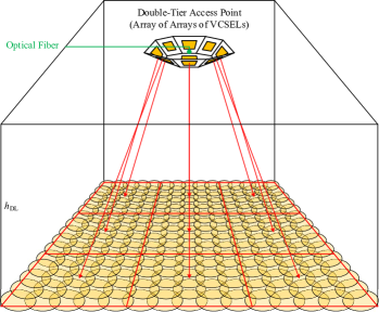
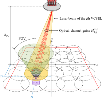
Fig. 1 depicts an indoor optical wireless network with full beam coverage by deploying a massive number of laser beams based on an array of arrays of VCSELs. The proposed double-tier AP design is composed of identical transmitter elements arranged as a array with a VCSEL array incorporated in each element. The total number of VCSELs used in this array of arrays architecture is . By choosing appropriate orientation angles for transmitter elements, each VCSEL array covers almost a ninth of the network area, as shown in Fig. 1. Note that the middle element of the AP that covers the central region of the network is not titled.
Figs. LABEL:sub@Fig:AP_a and LABEL:sub@Fig:AP_b show the optical design of the double-tier AP. The adjacent transmitter elements are placed at a center-to-center distance of . In each array, the VCSELs are placed close to each other with a pitch distance of . As a result, the beam spots may significantly overlap on the receiver plane. The beams can be separated from one another by using a plano-convex lens in front of each VCSEL array. This allows the light beams to be to refracted towards different directions so as to provide a high spatial resolution on the receiver plane. The refraction angle experienced by each beam depends on the lens thickness and the path it travels through within the lens. In order to achieve the desired spatial resolution, the lens parameters need to be properly adjusted based on the design requirements. The adjustable parameters of the plano-convex lens include the diameter , the radius of curvature , and the center thickness .
III-B Transmitter Element Modeling
When a Gaussian beam travels through a lens, its Gaussian characteristics are preserved [18]. If the propagation axis of the beam is aligned with the optical axis of the lens, it continues to propagate on the same optical axis after the lens. Otherwise, its propagation direction changes. In the following, we derive the parameters of the transformed Gaussian beam and the direction vector for each VCSEL in a transmitter element. Subsequently, we extend the analysis for the array of arrays architecture.
III-B1 Light Refraction
When light traverses a path between two media, it is refracted at the boundary. According to Snell’s law [18]:
| (7) |
where and , respectively, are the refractive index and the incident angle in the first medium, and and are the corresponding parameters for the second medium. Snell’s law can be expressed in vector form, leading to the law of refraction [18]:
| (8) |
where is the unit vector normal to the boundary surface, and are the normalized incidence and refraction vectors, respectively, and denotes the cross product. The refraction vector is given by [18]:
| (9) |
where denotes the inner product.

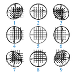
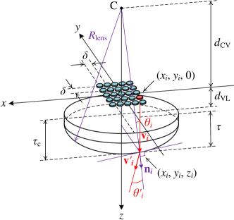
Fig. 3 illustrates the 3D geometry of the light refraction for the VCSEL array through the plano-convex lens based on the law of refraction. To elaborate, the VCSELs are labeled by a single index indicating their position in the array such that the th VCSEL signifies where for . Assuming that the center of the array sits at the origin of the system, the coordinates of the th VCSEL, for , are calculated as:
| (10a) | ||||
| (10b) | ||||
where and , and denotes the smallest integer value satisfying . The distance between the VCSEL array and the lens is represented by . For the th VCSEL, the beam waist is assumed to be located at . The beam is incident on the lens at with the propagation vector , where is the unit vector of the axis, exiting the lens at . Since the incident angle on the planar surface of the lens equals zero, the beam propagation axis remains unchanged upon entering the lens. When the beam reaches the convex surface of the lens, its propagation vector is changed due to the curvature of the surface as well as the change in the refractive index. By applying the law of refraction at the boundary for , , , and , , as shown in Fig. 3, the propagation vector of the refracted beam is derived as:
| (11) |
through the use of and . We need to determine , and . With the aid of Fig. 3, the angle of incidence and the normal vector on the convex surface of the lens are calculated as:
| (12) |
| (13) |
with and representing the unit vectors of the and axes, respectively. Note that:
| (14) |
Based on (7) and (12), the refraction angle is obtained as:
| (15) |
Combining (12)–(15) with (11), the expression of becomes:
| (16) |
through defining:
| (17) |
III-B2 Beam Transformation
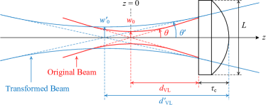
The propagation of light beams in optical systems is often described by ray transfer or ABCD matrices [18]. In this method, a matrix relates the position and angle of paraxial rays at the input and output planes of an optical system via linear algebraic equations. In the case of a Gaussian beam, the ABCD law applies to the -parameters of the original and transformed beams. Fig. 4 shows the Gaussian beam propagation through a plano-convex lens, assuming that the beam axis is parallel to the optical axis of the lens. The parameters of the transformed beam are denoted by , , , and , as defined in (2)–(5), and represents the distance of the new beam waist to the lens surface. Depending on the location of the input beam waist with respect to the lens, the output beam waist (i.e., the image) may be either real or virtual. We consider the case where a virtual beam waist is created behind the lens, since a real beam waist that is formed in front of the lens imposes a strict limitation on the maximum allowable transmit power due to eye safety [19].
In order to derive the parameters of the transformed beam, we use the -parameter transformation given by [18, 20]:
| (18) |
where:
| (19a) | ||||
| (19b) | ||||
| (19c) | ||||
| (19d) | ||||
where is the thickness of the lens through which the beam travels. From the geometry shown in Fig. 3, and . Combining these with (14) yields:
| (20) |
Now, we apply the transformation in (18) between the original beam at and the transformed beam at (i.e., at ), as shown in Fig. 4, so that:
| (21) |
By substituting the ABCD parameters from (19) into (21), the distance of the transformed beam waist from the tangent plane on the lens surface and the Rayleigh range of the transformed beam are derived as:
| (22) | ||||
| (23) |
where the operators and take the real and imaginary parts of a complex variable, respectively, and is the effective focal distance of the lens defined as [18]:
| (24) |
Based on (23), and by using (2), the radius of the transformed beam waist is obtained as:
| (25) |
III-C Total Spatial Intensity Distribution
In order to derive the total spatial intensity of the AP, the transmitter elements are indexed according to Fig. LABEL:sub@Fig:AP_b. Based on Euler angles with clockwise rotations, the titling of the th transmitter element about the and axes can be modeled using the following rotation matrices:
| (26a) | ||||
| (26b) | ||||
where the rotation angles are given as the th column of by:
| (27) |
Let the VCSELs in the array of arrays architecture be labeled by a global index of , and the th VCSEL lies in the th array for . The propagation vector of the refracted beam for the th VCSEL projected onto the coordinate system of the receiver plane can be expressed as:
| (28) | ||||
where is evaluated for based on (16). The coordinates of the th transmitter element are given by:
| (29) |
where , and is equal to the th column of given by:
| (30) |
For a given point of on the receiver plane, the distance vector from to is given by , and the corresponding Euclidean distance is:
| (31) |
Based on (1), the intensity distribution of the th beam on the receiver plane at can be expressed as:
| (32) |
where and for and , and is the radiance angle of the th beam relative to , which is calculated as:
| (33) |
The total spatial intensity of the AP is obtained as:
| (34) |
Note that and are functions of and through (31) and (33), respectively.

III-D Design Examples
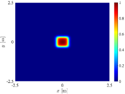
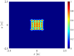
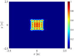
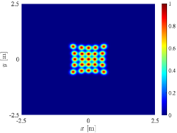
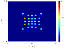
We provide numerical examples to demonstrate the AP design. The results are presented by assuming a wavelength of nm111Most commercially available VCSEL devices operate in an IR wavelength range of nm and they are generally cheaper than those operating at higher IR wavelengths such as nm. Nevertheless, the choice of higher wavelengths is beneficial in terms of eye safety considerations. and a beam waist radius of µm. For each VCSEL array, the total size is cm2 with a pitch distance of mm, and the array-to-lens distance is mm. To understand the effect of the design parameters on the spatial separation between the beam spots, Figs. 6 and 6 illustrate the normalized intensity distribution of the middle transmitter element on the receiver plane at m underneath the AP. In Fig. 6, a relatively large lens of diameter mm is used. In this case, for mm, the beams constitute a quasi-square coverage area, and for mm, they are still largely overlapping. When using mm, despite a slight overlap between the adjacent beam spots, the beams are sufficiently separated. In Fig. 6, a smaller lens with mm is used. It can be observed that by reducing the radius of curvature of the lens, refraction angles increase and the beams move considerably further apart.
Aiming to achieve a full beam coverage while maintaining non-overlapping beam spots, we opt for mm and mm. With this configuration, the beam spots cover the receiver plane in a complementary manner while the area covered by each of them is almost a circle of radius (i.e., the transformed beam spot radius containing of the transmit power carried by the beam), as shown in Fig. LABEL:sub@Fig:LensParameters2_a. We use this configuration for a room of size m3. To extend the AP coverage over the entire room area of m2, the transmitter elements are arranged next to each other at a distance of cm, as shown in Fig. LABEL:sub@Fig:AP_a. To obtain the required tilt angle for each transmitter element, the beam spot center of the central VCSEL in each array is assumed to be nearly landing on the intersection of the diagonals of the corresponding quadrilateral formed at the corners of the room, and this leads to . Fig. 7 shows the resulting spatial distribution of the normalized intensity on the receiver plane. To examine the accuracy of the proposed analytical modeling, the results are compared with ray tracing simulations in Zemax OpticStudio [21]. Comparing Figs. LABEL:sub@Fig:AP_Coverage_Analytical and LABEL:sub@Fig:AP_Coverage_Zemax, it can be seen that the analytical results and those obtained by using Zemax OpticStudio are closely matching.
IV Beam Clustering for Interference Management
IV-A Coordinated Multi-Beam Transmission
In order to achieve higher network throughput, it is desirable for every beam to fully utilize the available spectrum. However, the dense deployment of VCSELs in the double-tier AP and small sizes of beam spots unavoidably give rise to inter-beam interference (IBI) when the frequency spectrum is shared among multiple beams. Therefore, advanced interference mitigation techniques are required for improving the spectral efficiency and hence unlocking the capacity of the indoor access network. In this work, we use CoMB-JT, aiming to reduce IBI levels by coordinating transmissions from a cluster of beams. This is similar to coordinated multi-point (CoMP)-JT [22], though CoMB-JT proposed in this work does not necessarily originate from multiple points, but it is always formed with multiple beams which may come from the same transmitter element of the double-tier AP. This way, IBI can be effectively mitigated and converted into useful signals to enhance the downlink SINR especially for spot-edge users.
For beam clustering based on CoMP, three main categories are identified [23]: static clustering, semi-dynamic clustering, and dynamic clustering. In static clustering, once clusters are formed, they do not change with changes in the network. Static clusters are designed based on the network topology such as the geometry of the environment, the number of APs and their positions [23]. Semi-dynamic clustering is an enhanced version of static clustering where several layers of static clusters are formed to avoid inter-cluster interference (ICI) and users are associated with the best serving cluster. While semi-static clustering can improve potential performance gains compared to static clustering, the overlapping nature of clusters increases the system complexity [23]. In dynamic clustering, the system continuously adapts its clustering strategy to any changes in the network such as user mobility, inactive beams or load variations. Although with this scheme ICI can be minimized by dynamically adjusting cluster sizes for individual users, it comes with a higher complexity due to optimal scheduling.
The implementation complexity of CoMB increases with the number of coordinated beams and it can only be realized for a small cluster of beams in practice. The key for maximizing the benefits of CoMB lies in the optimum formation of clusters. By comparison, static clustering incurs significantly less complexity and is a suitable candidate for initial CoMB deployment in conjunction with the proposed double-tier AP.
IV-B Downlink System Modeling
Fig. 1 depicts the downlink system configuration where only the middle transmitter element of the double-tier AP is shown for convenience. There are a total of user devices distributed uniformly over a horizontal communication plane, and represents the vertical separation between the AP and user devices. The coverage area of the network is partitioned into non-overlapping regions, and each region is covered by an exclusive cluster of beams. According to CoMP-JT, each user device is assumed to be served by one cluster within a predefined region that provides the highest SINR. The coordinated VCSELs jointly send multiple copies of the same signal for each user. By using intensity modulation and direct detection (IM/DD), these signals are then detected at the same time by the receiver, and therefore their received powers are combined. Each user device is equipped with an ADR, the details of which are provided as follows.
IV-B1 Angle Diversity Receiver
A multi-element non-imaging ADR based on compound parabolic concentrators is adopted from [17], where we put forward the optimized multi-tier ADR design under the constraints on the overall field of view (FOV) and dimensions. The rationale behind choosing this receiver design is that the use of CPCs allows the maximum concentration gain to be achieved due to the law of conservation of Etendue [24], and it offers a robust performance by relieving strict alignment requirements and enabling connectivity to multiple light beams [25, 26]. We consider a single-tier ADR composed of seven identical elements oriented in the desired spatial directions, as shown in Fig. 8. Each receiver element comprises a dielectric CPC coupled with a 2D array of PIN PDs. A two-stage array processing is performed by applying equal gain combining (EGC) to the output signals of each PD array and maximum ratio combining (MRC) to the output signals of the receiver elements. The ADR parameters include , and , which denote the CPC acceptance angle, the PD area, and the number of PDs on the array, respectively. Also, and represent the areas of the CPC entrance and exit apertures, respectively. For each receiver element [17]:
| (35) |
where is the fill factor (FF) of the PD array. In addition, the geometrical concentration gain of a CPC is given by [24]:
| (36) |
where is the refraction index of the dielectric material. The half-angle FOV of the ADR is [17]. The normal vector of each receiver element can be described by using the azimuth and elevation angles, donated by and , respectively, for the th receiver element. According to the ADR structure, the elevation angle of the six elements around the middle one is the same as their tilting angle which is equal to [17], assuming that the ADR is oriented vertically upward. Consequently, for , and . The azimuth angle of the th receiver element is given by for , and . Hence, the normal vector of the th receiver element can be expressed in Cartesian coordinates as follows:
| (37) |
| (46) |
IV-B2 Optical Channel Gain
We use the coordinate system shown in Fig. 8 for analysis. The th user device is located at . The distance vector from the th transmitter element of the AP to is given by , and:
| (38) |
The incident beam intensity of the th VCSEL with a radiance angle of with respect to the user position is:
| (39) |
where , for . Therefore, the optical power received by the th ADR element of the user device can be expressed as:
| (40) |
where is the incidence angle of the beam with respect to the normal vector of the th receiver element. The last factor in (40) is an indicator function which is defined as if , and otherwise. By using (35)–(40), the direct current (DC) gain of the downlink channel between the th VCSEL and the th receiver element of the th user device can be derived as:
| (41) | ||||
Let represent the index set of the VCSELs participating in the th cluster for . Once the users joined their clusters, the th cluster serves a subset of the users with members such that . The users in the network are globally indexed from to and those served by the th cluster are indicated by the index set with . The optical power received by the th receiver element of the th user from the th cluster and the corresponding total received power are given by:
| (42a) | ||||
| (42b) | ||||
where is the equivalent DC gain of the CoMB-JT channel between the th cluster and the th user such that:
| (43) |
IV-B3 Noise Model
Noise sources at the receiver consist of the thermal noise and shot noise, and the laser noise arising from the VCSELs. For the th receiver element of the th user, the total noise is modeled as a white Gaussian noise with a single-sided power spectral density (PSD) of [13]:
| (44) |
where is the Boltzmann constant, is temperature in Kelvin, is the load resistance, is the preamplifier noise figure, is the elementary charge, and is the PSD of the relative intensity noise (RIN), defined as the mean square of intensity fluctuations normalized to the squared average intensity [27]. The total noise variance is given by , where is the single-sided bandwidth of the system which is determined by the receiver bandwidth, as VCSELs typically have a very large modulation bandwidth (e.g., in excess of GHz [28]).
IV-C Multi-User Performance Analysis
To ensure a high spectral efficiency, we assume the use of DCO-OFDM based on an -point fast Fourier transform (FFT) with adaptive quadrature amplitude modulation (QAM). Thus, data-carrying subcarriers are available for each VCSEL. The average electrical power, , is related to the average transmit optical power, , by , so that the clipping distortion remains negligible [29]. We apply NOMA and OFDMA techniques for the downlink multi-user access. The received SINR and achievable rate expressions for these techniques are provided in the following.
IV-C1 Multi-User Access
In NOMA, spectral resources (i.e., orthogonal frequency division multiplexing (OFDM) subcarriers) are fully shared by every user in a cluster and downlink transmissions for different users are multiplexed in the power domain based on superposition coding. In principle, for each cluster, the superposed signal is broadcast to all the involved users and successive interference cancellation (SIC) is applied at the receiver side for multi-user detection. For each user, SIC is performed by detecting and canceling the interference caused by other users with weaker channel conditions while treating the interference originating from those with stronger channel conditions as noise.
| (47) |
| (48) |
Without loss of generality, suppose that the channel gains of the users associated with the th cluster are sorted in an ascending order such that:
| (45) |
for . Let be the optical power allocation coefficient corresponding to the th user in the th cluster. The total power constraint implies that . To maintain fairness among users, a suitable power allocation policy is one that prioritizes the users that have weaker channel conditions. In this case, it follows from (45) that . The power allocation coefficients are chosen as , where [30]. Upon removing the DC term, the received signal at the th receiver element of the th user in the th cluster is expressed as (46), given at the top of the page, where the message symbols are assumed to be drawn from a normalized QAM constellation, and the factor ensures that the average power of the time domain signal is normalized to unity. Also, the noise terms are independent Gaussian random variables with a zero mean and variance , and the factor is the subcarrier utilization ratio. The received signals, for , are combined together in the form of , where is the corresponding combining weight. The receiver fully decodes the SIC term, and then subtracts its remodulated version from the received signal before proceeding to decode the th user’s message. During the whole decoding process, the receiver treats both the residual multi-user interference (MUI) in the same cluster and the ICI from the rest of the clusters as noise. Assuming perfectly error-free SIC operations, the SINR of the th user in the th cluster is given by (47) at the top of next page, where . Based on MRC, the combining weight for each receiver element is proportional to its received photocurrent to noise ratio [31], resulting in (48) at the top of the page.
When using OFDMA, a fraction of the total bandwidth and a fraction of the total power are allocated to the th user in the th cluster subject to and . Hence, under OFDMA, the intra-cluster MUI is eliminated and the ICI remains as the residual interference. The SINR of the th user in the th cluster can be written as:
| (49) |
The MRC weights for OFDMA are given by:
| (50) |
IV-C2 Sum Rate Analysis
For an additive white Gaussian noise (AWGN) channel, using adaptive QAM, a tight upper bound of the achievable rate for dB is given by [32]:
| (51) |
and is the signal-to-noise ratio (SNR) gap accounting for the required BER performance.
The achievable rate of the th user in the th cluster under NOMA and OFDMA is deduced from (51) as:
| (52) |
where for NOMA and OFDMA is given by (47) and (49), respectively. The sum rate for all clusters of the network is computed by:
| (53) |
The multi-user fairness is measured by means of Jain’s fairness index [33], which is defined as follows:
| (54) |
| Parameter | Description | Value |
|---|---|---|
| Vertical separation | m | |
| Beam waist radius | µm | |
| VCSEL wavelength | nm | |
| Transmit optical power per VCSEL | mW | |
| RIN PSD | dB/Hz | |
| Lens refractive index | ||
| CPC refractive index | ||
| PD responsivity | AW | |
| Number of PDs per PD array | ||
| ADR half-angle FOV | ||
| Preamplifier noise figure | dB | |
| System bandwidth | GHz | |
| Pre-FEC BER |
V Numerical Results and Discussions
In this section, we evaluate the proposed double-tier AP design for an indoor multi-user access network based on static clustering. The simulation setup consists of an indoor environment as depicted in Fig. 1 with dimensions of m3. The remaining simulation parameters are listed in Table I, unless otherwise specified. Assuming that the receiver is oriented upwards, it requires a half-angle FOV of at least to be able to receive signals in regions close to the walls. To this end, the half-angle FOV of the ADR is assumed to be . The transmit optical power of mW per VCSEL is chosen on account of eye safety for each transmitter element based on International electrotechnical commission (IEC) 60825-1 and American national standards institute (ANSI) Z136.1 standards [34, 35, 36]. The full treatment of eye safety is beyond the scope of this paper. In an earlier study [19], we have developed an algorithm for eye safety analysis of a VCSEL array combined with a lens, which computes the maximum transmit power per VCSEL for this purpose.
V-A Clustering Scenarios: Spatial Distribution of Data Rate
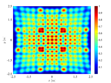
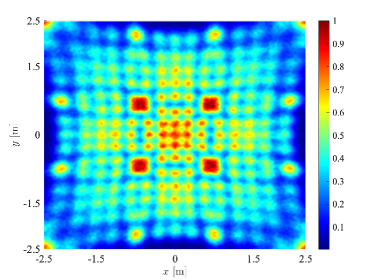
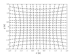
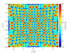
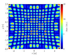
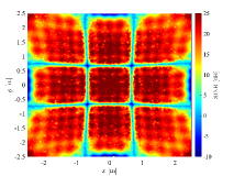
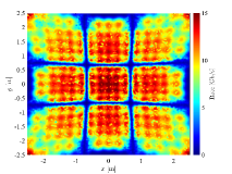
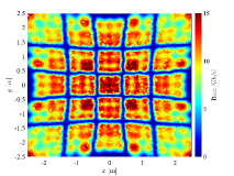
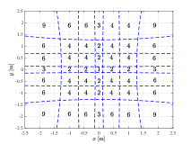
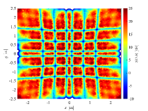
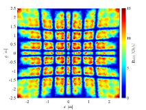
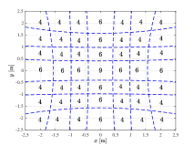
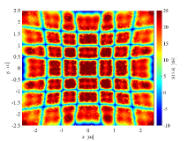
In the baseline clustering scenario, every single beam is considered to be carrying independent data for its coverage spot. In this case, clusters are of size one, creating a pure space division multiple access (SDMA) network with the highest possible spatial reuse of the spectral resources. Since the bandwidth is fully reused across the network, the adjacent beams interfere with one another. Fig. LABEL:sub@Fig:6_NoClustering_a illustrates the approximate borders of the beam spots on the receiver plane. Fig. LABEL:sub@Fig:6_NoClustering_b demonstrates the spatial distribution of the received SINR on the same plane. The maximum SINR of dB is realized at the centers of the beam spots and the SINR value is on the order of dB at the edge of the network, i.e., in proximity to the walls. To obtain the spatial distribution of the achievable rate, the SINR values are mapped onto their respective data rates based on (52) by assuming that each cluster serves a single user222Note that when there is a single user per cluster, achievable rates for NOMA and OFDMA are the same according to (52).. This hypothetical assumption helps to understand the performance bounds in different locations over the coverage area of the AP. According to Fig. LABEL:sub@Fig:6_NoClustering_c, data rates are about Gb/s to Gb/s at the centers of the beam spots except in locations near the walls where still a data rate of Gb/s is provided. For the baseline SDMA, the total number of clusters equals the total number of VCSELs in the AP, i.e., .
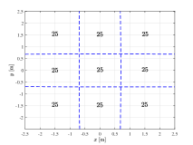
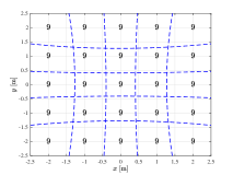
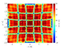

Besides the baseline SDMA, we put forward four static clustering scenarios aiming to address interference management for the multi-beam optical wireless access network. The proposed clustering scenarios along with their corresponding SINR and data rate distributions are presented in Fig. 10. For each scenario, the left diagram depicts the clustering layout, and the displayed numbers indicate the cluster size. The total number of clusters considered for scenarios to , respectively, is . In scenario , as shown in Fig. LABEL:sub@Fig:6_Scenarios_a, each cluster consists of coordinated VCSELs. In this case, each VCSEL array at the AP constitutes a separate cluster of size . In scenario , as shown in Fig. LABEL:sub@Fig:6_Scenarios_b, clusters are of a smaller size, with each one having coordinated VCSELs. In scenarios and , shown in Figs. LABEL:sub@Fig:6_Scenarios_c and LABEL:sub@Fig:6_Scenarios_d, respectively, the size of clusters varies across the room. It can be observed that for all these scenarios, data rate values range from Gb/s to Gb/s, similar to the baseline SDMA. The difference of the scenarios is in the distribution of their ‘hot’ (i.e., high data rate) and ‘cold’ (i.e., low data rate) regions as a result of the different clustering layouts used.
Moreover, in scenarios and in which clusters of an equal size are employed, the central cluster yields the highest data rate level, while the overall data rate values reduce for the neighboring clusters. Due to the symmetrical structure of the array of arrays of VCSELs and the spatial tilting patterns of the beams for the arrays around the central array in the AP, the clusters encompassing the and axes on the receiver plane produce higher data rates than those lying diagonally on the plane. This can be explained by the fact that the clusters formed on the diagonal bisectors of the plane are subject to a higher link distance from the AP. Furthermore, compared to scenario , scenario brings about a more even data rate distribution because of using a larger size for its clusters. In scenario , different numbers of VCSELs are assigned to clusters, as shown in Fig. LABEL:sub@Fig:6_Scenarios_c. The rationale behind choosing these numbers is that we need to enlarge the size of clusters in proportion to their distance from the room center, in horizontal, vertical and diagonal directions on the plane, so as to compensate for reduction in the received power by incorporating more VCSELs in CoMP-JT. Note that the central region is mainly covered by the middle VCSEL array of the AP which has no tilt angle, while other regions are covered by the tilted VCSEL arrays. It is observed that this scenario performs worse than the first two scenarios with uniformly sized clusters in terms of the data rate distribution. By contrast, in scenario , shown in Fig. LABEL:sub@Fig:6_Scenarios_d, when the size of the central cluster is changed to and the size of the clusters along the and axes is equally increased to while the same size of is kept for the rest of clusters, the resulting data rate distribution is better than that obtained by scenario .


V-B Clustering Scenarios: Multi-User Performance Evaluation
We study the multi-user performance of the proposed clustering scenarios in terms of the sum rate and the fairness of the network based on Monte Carlo simulations by uniformly distributing the 2D coordinates of users in the room. The statistics of the performance metrics are evaluated over random realizations.
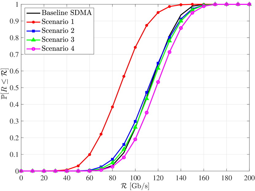
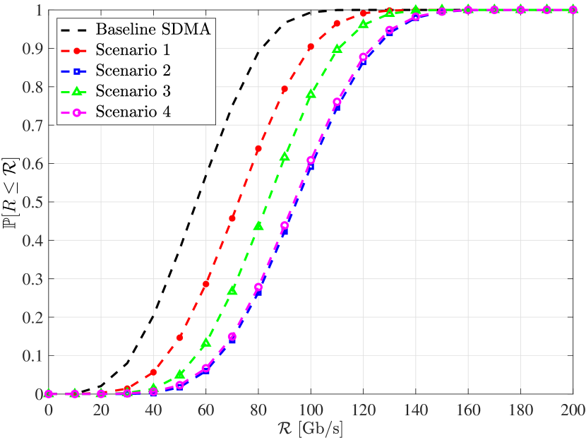
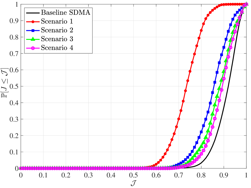
First, let us consider the case where the number of users is fixed at as a representative example of low number of users. The cumulative distribution functions of the sum rates offered by the clustering scenarios under NOMA and OFDMA are plotted in Fig. 13, where denotes the probability of an event. In the case of NOMA, it can be observed from Fig. LABEL:sub@Fig:6_CDF1_10_SumRate_a that scenarios and result in a worse sum rate performance relative to the baseline SDMA, whereas scenarios and improve the performance. The sum rate for scenario closely follows that delivered by SDMA. However, for scenario , there is a large gap as compared to SDMA. Unlike NOMA, when OFDMA is applied, as shown in Fig. LABEL:sub@Fig:6_CDF1_10_SumRate_b, it is evident that the sum rate for all four scenarios is always improved with respect to SDMA, as in OFDMA, the SINR improvement by CoMB-JT is a dominant factor leading to better data rates per user when the size of clusters .
The CDFs of the fairness indices are presented in Fig. 13. For NOMA, it can be observed from Fig. LABEL:sub@Fig:6_CDF1_10_Fairness_a that the fairness performance for all the clustering scenarios is poorer than that achieved by SDMA. By contrast, when OFDMA is in use, the fairness index is effectively heightened by the clustering scenarios and a better performance is attained in comparison with SDMA, likewise the sum rate results for OFDMA.
To further shed light into the multi-user performance, let us turn our attention to the average performance metrics. The average sum rate is defined as the ergodic average of the sum rate, i.e., where denotes the expected value of a random variable. The average fairness index is computed as . The results are mainly presented as a function of user density , which is defined as the normalized number of users per unit area of the room:
| (55) |
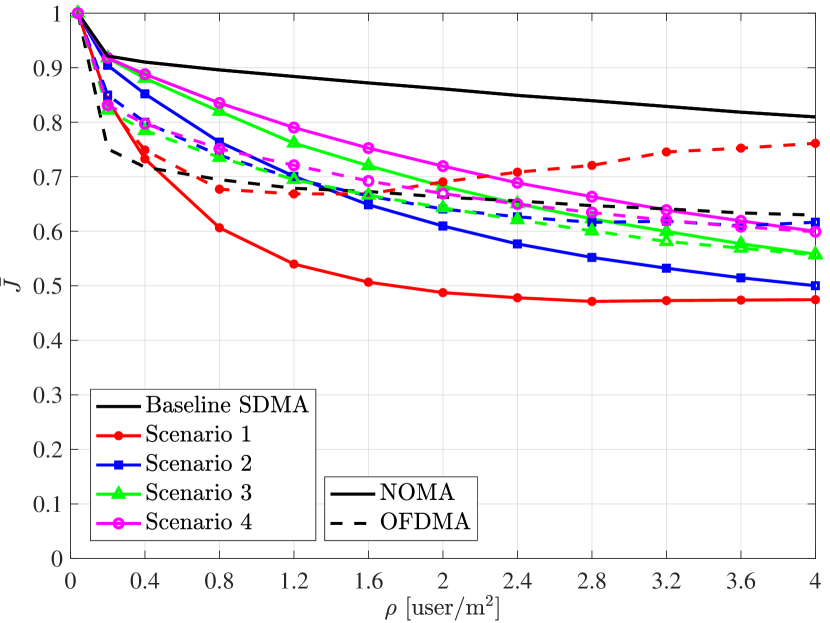
Fig. 13 shows the average performance metrics for both NOMA and OFDMA for comparison over a range of user densities up to , equivalent to users. From Fig. LABEL:sub@Fig:6_AvgPerformance1_a, it can be observed that in both cases, the average sum rate is a monotonically increasing function of . Also, NOMA clearly outperforms OFDMA in terms of the average sum rate for all the clustering scenarios. In the case of NOMA, for low user densities of , scenarios and slightly improve the performance over SDMA. By increasing , SDMA takes the lead and its average sum rate approaches Tb/s for high user densities. Under OFDMA, all the scenarios provide gain with respect to SDMA over a range of , where for scenarios to , respectively. For both NOMA and OFDMA, as the user intensity increases, the average sum rate performance for all four scenarios converges to a constant value, which is scaled up with the number of clusters. Among the devised scenarios, scenario with has the best performance and scenario , though having the same number of clusters, holds the second best place. This highlights the point that the strategy used for adjusting the size of clusters in scenario is more efficient than that used in scenario . We note that for both cases of NOMA and OFDMA, the sum rate is primarily limited in scenario in comparison with the other scenarios. The reason for this relates to the use of large clusters as shown in Fig. 10, which leads to a significant underutilisation of the spectral resources over the network. Also, since the channel gain is almost uniformly distributed over the area of each cluster in scenario , the gain of NOMA over OFDMA for high user densities is less than when scenarios with smaller clusters are deployed.
From the perspective of the average fairness index as shown in Fig. LABEL:sub@Fig:6_AvgPerformance1_b, SDMA with NOMA retains the highest performance. For NOMA, all the scenarios exhibit a monotonically decreasing behavior with . Under OFDMA, a similar trend is observed for all the scenarios excluding scenario 1, by which the fairness index raises for and is notably greater than that achieved by the baseline SDMA at . Furthermore, OFDMA performs better than NOMA in scenarios and and the performance gap of the two schemes becomes larger as increases. By comparison, NOMA brings about higher fairness indices in scenarios and , and the performance gap between NOMA and OFDMA is consistently reduced when increases.
VI Conclusions
We proposed the design of a novel double-tier AP architecture built upon a array of VCSEL arrays to establish an indoor grid-of-beam optical wireless access network. A full beam coverage with minimum overlaps between the beam spots were achieved by properly configuring the orientation angle of individual arrays. We introduced various beam clustering scenarios for downlink interference management and studied the multi-user performance of the network based on NOMA and OFDMA by considering a baseline SDMA scheme whereby the system bandwidth is reused for every single beam. The results evince the superior performance of SDMA with NOMA in terms of the sum rate and the fairness index especially for higher user densities. In this case, the average sum rate of the network approaches Tb/s when the user density exceeds . Instead, performance gains of the clustering scenarios are evident for OFDMA. Particularly, scenario with clusters of balanced sizes yields improvement in the average sum rate performance compared to the baseline SDMA for a user density of . On the other hand, scenario in which every VCSEL array is considered as a cluster of size improves the average fairness performance by relative to the baseline SDMA for a user density of . These results are indicative of the effectiveness of clustering-based interference management in the OFDMA network. Future works include the optimization of the design parameters under quality of service constraints.
Acknowledgement
The authors acknowledge financial support by the Engineering and Physical Sciences Research Council (EPSRC) under grant EP/S016570/1 ‘Terabit Bidirectional Multi-User Optical Wireless System (TOWS) for 6G LiFi’. The authors also acknowledge discussions with Dr. Mohammad Dehghani Soltani during early stages of this work in 2021.
References
- [1] M. Giordani, M. Polese, M. Mezzavilla, S. Rangan, and M. Zorzi, “Toward 6G Networks: Use Cases and Technologies,” IEEE Commun. Mag., vol. 58, no. 3, pp. 55–61, Mar. 2020.
- [2] E. Calvanese Strinati, S. Barbarossa et al., “6G: The Next Frontier: From Holographic Messaging to Artificial Intelligence Using Subterahertz and Visible Light Communication,” IEEE Veh. Technol. Mag., vol. 14, no. 3, pp. 42–50, Sep. 2019.
- [3] T. Koonen, “Indoor Optical Wireless Systems: Technology, Trends, and Applications,” Journal of Lightwave Technology, vol. 36, no. 8, pp. 1459–1467, Apr. 2018.
- [4] T. Koonen, K. Mekonnen et al., “Ultra-high-capacity wireless communication by means of steered narrow optical beams,” Philosophical Transactions of the Royal Society A: Mathematical, Physical and Engineering Sciences, vol. 378, 2020.
- [5] T. Koonen, F. Gomez-Agis et al., “High-Capacity Optical Wireless Communication Using Two-Dimensional IR Beam Steering,” IEEE/OSA J. Lightw. Technol., vol. 36, no. 19, pp. 4486–4493, 2018.
- [6] K. Wang, Z. Yuan et al., “Experimental Demonstration of Indoor Infrared Optical Wireless Communications with a Silicon Photonic Integrated Circuit,” IEEE J. Lightw. Technol., vol. 37, no. 2, pp. 619–626, 2018.
- [7] K. Wang, A. Nirmalathas, C. Lim, and E. Skafidas, “High-Speed Optical Wireless Communication System for Indoor Applications,” IEEE Photon. Technol. Lett., vol. 23, no. 8, pp. 519–521, 2011.
- [8] Y. Hong, F. Feng et al., “Demonstration of Tbit/s WDM OWC with wavelength-transparent beam tracking-and-steering capability,” Opt. Express, vol. 29, no. 21, pp. 33 694–33 702, Oct 2021.
- [9] R. Singh, F. Feng, Y. Hong et al., “Design and Characterisation of Terabit/s Capable Compact Localisation and Beam-Steering Terminals for Fiber-Wireless-Fiber Links,” J. Lightw. Technol., vol. 38, no. 24, pp. 6817–6826, 2020.
- [10] T. Koonen, J. Oh et al., “Ultra-High Capacity Indoor Optical Wireless Communication Using 2D-Steered Pencil Beams,” IEEE/OSA J. Lightw. Technol., vol. 34, no. 20, pp. 4802–4809, 2016.
- [11] C. Sun, X. Gao, J. Wang, Z. Ding, and X.-G. Xia, “Beam Domain Massive MIMO for Optical Wireless Communications With Transmit Lens,” IEEE Trans. Commun., vol. 67, no. 3, pp. 2188–2202, Mar. 2019.
- [12] C. Sun, J. Wang, X. Gao, and Z. Ding, “Networked Optical Massive MIMO Communications,” IEEE Transactions on Wireless Communications, vol. 19, no. 8, pp. 5575–5588, Aug. 2020.
- [13] E. Sarbazi, H. Kazemi, M. D. Soltani, M. Safari, and H. Haas, “A Tb/s Indoor Optical Wireless Access System Using VCSEL Arrays,” in 2020 IEEE 31st Annual International Symposium on Personal, Indoor and Mobile Radio Communications, 2020, pp. 1–6.
- [14] H. Kazemi, E. Sarbazi et al., “A Tb/s Indoor MIMO Optical Wireless Backhaul System Using VCSEL Arrays,” IEEE Transactions on Communications, vol. 70, no. 6, pp. 3995–4012, 2022.
- [15] R. Michalzik, VCSELs: Fundamentals, Technology and Applications of Vertical-Cavity Surface-Emitting Lasers. Springer, 2012, vol. 166.
- [16] Y. Liu, A. Wajahat, R. Chen, N. Bamiedakis, M. Crisp, I. H. White, and R. V. Penty, “High-Capacity Optical Wireless VCSEL Array Transmitter with Uniform Coverage,” in Free-Space Laser Communications XXXV, vol. 12413, International Society for Optics and Photonics. SPIE, 2023.
- [17] E. Sarbazi, H. Kazemi et al., “Design and Optimisation of High-Speed Receivers for 6G Optical Wireless Networks,” IEEE Transactions on Communications, vol. 72, no. 2, pp. 971–990, 2024.
- [18] B. E. A. Saleh and M. C. Teich, Fundamentals of Photonics, 3rd ed. John Wiley & Sons, Inc., 2019, vol. Part I: Optics.
- [19] H. Kazemi, E. Sarbazi, M. Safari, and H. Haas, “Multi-Beam Access Point Design for 6G Laser-Based Optical Wireless Networks: Eye Safety-Coverage Tradeoff,” in 2023 IEEE Global Communications Conference (GLOBECOM), 2023.
- [20] S. Nemoto, “Transformation of Waist Parameters of a Gaussian Beam by a Thick Lens,” Applied Optics, vol. 29, no. 6, pp. 809–816, 1990.
- [21] “Ansys Zemax OpticStudio.” [Online]. Available: https://www.zemax.com/products/opticstudio
- [22] H. Ma, L. Lampe, and S. Hranilovic, “Coordinated Broadcasting for Multiuser Indoor Visible Light Communication Systems,” IEEE Trans. Commun., vol. 63, no. 9, pp. 3313–3324, Sep. 2015.
- [23] S. Bassoy, H. Farooq, M. A. Imran, and A. Imran, “Coordinated Multi-Point Clustering Schemes: A Survey,” IEEE Communications Surveys & Tutorials, vol. 19, no. 2, pp. 743–764, 2017.
- [24] R. Winston, J. C. Miñano, P. G. Benitez et al., Nonimaging Optics. Elsevier, 2005.
- [25] Z. Chen, D. A. Basnayaka, X. Wu, and H. Haas, “Interference Mitigation for Indoor Optical Attocell Networks Using an Angle Diversity Receiver,” Journal of Lightwave Technology, vol. 36, no. 18, pp. 3866–3881, 2018.
- [26] E. Sarbazi, H. Kazemi, H. Haas, and M. Safari, “A Robust and Compact Non-Imaging Angle Diversity Receiver for 6G Optical Wireless Communications,” in 2023 IEEE International Conference on Communications Workshops (ICC Workshops), 2023, pp. 01–06.
- [27] L. A. Coldren, S. W. Corzine, and M. L. Masanovic, Diode Lasers and Photonic Integrated Circuits, 2nd ed. John Wiley & Sons, Inc., 2012.
- [28] N. N. Ledentsov, O. Y. Makarov, V. A. Shchukin, V. P. Kalosha, N. Ledentsov, L. Chrochos, M. B. Sanayeh, and J. P. Turkiewicz, “High Speed VCSEL Technology and Applications,” Journal of Lightwave Technology, vol. 40, no. 6, pp. 1749–1763, 2022.
- [29] S. Dimitrov, S. Sinanovic, and H. Haas, “Clipping Noise in OFDM-Based Optical Wireless Communication Systems,” IEEE Trans. Commun., vol. 60, no. 4, pp. 1072–1081, Apr. 2012.
- [30] Z. Ding, Z. Yang, P. Fan, and H. V. Poor, “On the Performance of Non-Orthogonal Multiple Access in 5G Systems with Randomly Deployed Users,” IEEE Signal Processing Letters, vol. 21, no. 12, pp. 1501–1505, 2014.
- [31] J. Carruther and J. M. Kahn, “Angle Diversity for Nondirected Wireless Infrared Communication,” IEEE Transactions on Communications, vol. 48, no. 6, pp. 960–969, Jun. 2000.
- [32] A. J. Goldsmith and S.-G. Chua, “Variable-Rate Variable-Power MQAM for Fading Channels,” IEEE Trans. Commun., vol. 45, no. 10, pp. 1218–1230, Oct. 1997.
- [33] R. K. Jain, D. M. W. Chiu, and W. R. Hawe, “A Quantitative Measure of Fairness and Discrimination for Resource Allocation in Shared Systems,” Digital Equipment Corporation, Technical Report, DEC-TR-301, 1984.
- [34] Safety of Laser Products - Part 1: Equipment Classification, Requirements and User’s Guide, International Electrotechnical Commission (IEC) 60825-1:2014 Std., Aug. 2014.
- [35] Recommended Practice for Laser Safety Measurements for Hazard Evaluation, American National Standards Institute (ANSI) Z136.4-2021 Std., 2021.
- [36] R. Henderson and K. Schulmeister, Laser Safety. CRC Press, 2003.
![[Uncaptioned image]](/html/2404.04443/assets/Photos/Hossein.jpg) |
Hossein Kazemi (Member, IEEE) received the M.Sc. degree in electrical engineering (microelectronic circuits) from the Sharif University of Technology, Tehran, Iran, in 2011, the M.Sc. degree (Hons.) in electrical engineering (communication systems) from Ozyegin University, Istanbul, Turkey, in 2014, and the Ph.D. degree in electrical engineering from the Institute for Digital Communications, The University of Edinburgh, Edinburgh, U.K., in 2019. He is currently a Postdoctoral Research Associate at the LiFi Research and Development Centre, University of Cambridge, Cambridge, U.K. His main research interests include wireless communications, optical wireless communications, and 6G. |
![[Uncaptioned image]](/html/2404.04443/assets/Photos/Elham.jpg) |
Elham Sarbazi (Member, IEEE) received the Ph.D. degree in Electrical Engineering from the University of Edinburgh, U.K., in 2019. She was a Postdoctoral Research Associate at the LiFi Research and Development Centre, University of Strathclyde, Glasgow, U.K. She was the recipient of the Best Paper Award for the 2022 IEEE Global Communications Conference (GLOBECOM). Her current research mainly focuses on 6G optical wireless communications. |
![[Uncaptioned image]](/html/2404.04443/assets/Photos/Michael.jpg) |
Michael Crisp (Member, IEEE) received the MEng and Ph.D. degrees from the University of Cambridge, Cambridge, U.K. in 2005 and 2010 respectively. His PhD was focused on the use of analog radio over fibre for distributed antenna networks. He is currently an Associate Professor of RF systems with the Engineering Department at University of Cambridge. His current research interests include RF systems for next generation battery-less sensors, radio over fibre systems, microwave photonics and optical wireless communications. He has authored and co-authored over 70 conference and journal publications and co-founded a spin out company PervasID Ltd. He was a recipient of the Royal Academy of Engineering Young Entrepreneurs Award in 2011. |
![[Uncaptioned image]](/html/2404.04443/assets/Photos/Taisir.jpg) |
Taisir Elgorashi received the B.S. degree (Hons.) in electrical and electronic engineering from the University of Khartoum, Khartoum, Sudan, in 2004, the M.Sc. degree (Hons.) in photonic and communication systems from the University of Wales, Swansea, UK, in 2005, and the Ph.D. degree in optical networking from the University of Leeds, Leeds, UK, in 2010. She is currently a Senior Lecturer (Associate Professor) with the Department of Engineering, King’s College London, London, UK. Before joining King’s College London, she was a lecturer in optical networks with the School of Electronic and Electrical Engineering, University of Leeds from 2015 to 2022 and held a postdoctoral research position at the same school from 2010 to 2014, where she focused on the energy efficiency of optical networks investigating the use of renewable energy in core networks, green data centres, distributed cloud computing and network virtualization. The energy efficiency techniques developed by her contributed three out of eight carefully chosen core network energy efficiency improvement measures recommended by the GreenTouch consortium, a consortium of 55 leading ICT industry and academic research organisations, for every operator network worldwide. She was a BT Research Fellow in in 2012 studying hybrid wireless optical broadband access networks. Her work led to several invited talks at GreenTouch, Bell Labs, the Optical Network Design and Modelling Conference, the Optical Fiber Communications Conference, the International Conference on Computer Communications, and the EU Future Internet Assembly in collaboration with Alcatel-Lucent and Huawei. She was awarded the IET 2016 Premium Award for best paper in IET Optoelectronics. She co-chaired multiple times the Green Communication Systems and Networks (GCSN) symposium in the IEEE Communication Society (ComSoc) flagship conferences, ICC (2020, 2023) and GLOBECOM (2016, 2018). She is currently an associate Editor in IET Optoelectronics and IEEE Transactions on Green Communications and Networking. |
![[Uncaptioned image]](/html/2404.04443/assets/Photos/Jaafar.jpg) |
Jaafar Elmirghani (Fellow, IEEE) holds a Chair in Communication Networks and Systems in Kings College London and was for 15 years the Director of the Institute of Communication and Power Networks, University of Leeds, UK. He is Fellow of IEEE, Fellow of IET and Fellow of Institute of Physics and has provided outstanding leadership in a number of large research projects, secured over £30m in grants and was PI of the £6m EPSRC Intelligent Energy Aware Networks (INTERNET) Programme Grant, 2010-2016. He is Co-Chair of the IEEE Sustainable ICT initiative, a pan IEEE Societies initiative responsible for Green ICT activities across IEEE, 2012-present. He was awarded in international competition the IEEE Comsoc 2005 Hal Sobol award; 3 IEEE Comsoc outstanding technical achievement and service awards (2009, 2015, 2020); the 2015 GreenTouch 1000x award; IET Optoelectronics 2016 Premium Award for work on energy efficiency and shared the 2016 Edison Award in the collective disruption category with a team of 6 from GreenTouch and Nokia Bell Labs for joint work on the GreenMeter. His work led to 5 IEEE standards with a focus on cloud and fog computing and energy efficiency, where he currently heads the Working Group responsible for IEEE P1925.1, IEEE P1926.1, IEEE P1927.1, IEEE P1928.1 and IEEE P1929.1 standards; this resulting in significant impact through industrial and academic uptake. He was elected Fellow of IEEE in 2021 for “Contributions to Energy-Efficient Communications”. He was Area Editor of the IEEE Journal on Selected Areas in Communications (JSAC) series on Machine Learning for Communications and is PI of the EPSRC £6.6m Terabit Bidirectional Multi-user Optical Wireless System (TOWS) for 6G LiFi, 2019-2024. He has published over 600 technical papers, received a number of best paper awards and has research interests in energy efficiency, optimisation, machine learning and optical wireless systems and networks. |
![[Uncaptioned image]](/html/2404.04443/assets/Photos/Richard.jpg) |
Richard V. Penty (Senior Member, IEEE) received the Ph.D. degree in engineering from the University of Cambridge, U.K., in 1989. He was a Science and Engineering Research Council IT Fellow researching all optical nonlinearities in waveguide devices in Cambridge. In 2019, he was appointed as the Deputy Head of the School of Technology, University of Cambridge, and the Deputy Vice Chancellor in 2020, becoming the Head of the School of Technology in 2023. He is currently a Professor of photonics with the University of Cambridge, having previously held academic posts with the University of Bath and the University of Bristol. His research interests include high-speed optical communication systems, photonic integration, optical switching, and sensing systems and quantum communications. He is a fellow of the Royal Academy of Engineering and the IET. He was the Editor-in-Chief of the IET Optoelectronics journal from 2006 to 2019. |
![[Uncaptioned image]](/html/2404.04443/assets/Photos/Ian.jpg) |
Ian H. White (Fellow, IEEE) received the B.A. and Ph.D. degrees from the University of Cambridge, Cambridge, U.K., in 1980 and 1984, respectively. He was then appointed as a Research Fellow and an Assistant Lecturer at the University of Cambridge before becoming a Professor of physics at the University of Bath, Bath, U.K., in 1991. In 1996, he moved to the University of Bristol, Bristol, U.K., as a Professor of optical communications, where he became the Head of the Department of Electrical and Electronic Engineering in 1998. He returned to the University of Cambridge in October 2001, where he became the Head of the School of Technology in 2005 and subsequently the Chair. He left the School of Technology, University of Cambridge, to take up the position of ProVice-Chancellor for Institutional Affairs in 2010. He joined the University of Bath from the University of Cambridge where he had been the Master of Jesus College, the van Eck Professor of engineering, the Deputy Vice-Chancellor, and the Head of Photonics Research in the Electrical Division, Department of Engineering. His research interests are in photonics, including optical data communications and laser diode-based devices. Dr. White was a member of the Board of Governors of the IEEE Photonics Society from 2008 to 2012. He is also a Fellow of the U.K. Royal Academy of Engineering and the Institution of Engineering and Technology. He is also the Editor-in-Chief of Electronics Letters and Microsystems and Nanoengineering (Nature). |
![[Uncaptioned image]](/html/2404.04443/assets/Photos/Majid.jpg) |
Majid Safari (Senior Member, IEEE) received Ph.D. in Electrical and Computer Engineering from the University of Waterloo, Canada in 2011. He is currently a Professor of Optical and Wireless Communications at the University of Edinburgh and an associate editor of IEEE Transactions on Communications. Prof Safari has published more than 150 papers and is a recipient of Mitacs Fellowship and prestigious grants from Leverhulme Trust and EPSRC. His main research interests include the application of optics, information theory and signal processing in optical, wireless, and quantum communications. |
![[Uncaptioned image]](/html/2404.04443/assets/Photos/Harald.jpg) |
Harald Haas (Fellow, IEEE) received the Ph.D. degree from the University of Edinburgh, Edinburgh, U.K., in 2001. He currently is the Van Eck Professor of Engineering at the University of Cambridge and the Director of the LiFi Research and Development Centre. He founded pureLiFi Ltd. and holds the position of Chief Scientific Officer (CSO). His most recent research interests lie in integrating physics and communication theory to design secure, high-speed wireless multi-user access networks and distributed x-haul networks utilising the optical spectrum toward building net-zero and pervasive wireless networks. He has co-authored more than 650 conference and journal papers with more than 55,000 citations and holds more than 45 patents. He has been listed as highly cited researcher by Clarivate/Web of Science since 2017. Prof. Haas has delivered two TED talks and one TEDx talk which have been watched online more than 5.5 million times. In 2016, he was the recipient of the Outstanding Achievement Award from the International Solid State Lighting Alliance. Prof Haas was awarded a Royal Society Wolfson Research Merit Award in 2017. In 2019 he received the IEEE Vehicular Society James Evans Avant Garde Award and the Enginuity The Connect Places Innovation Award in 2021. In 2022 he was the recipient of a Humboldt Research Award for his research achievements. In 2023, Prof Haas among the three shortlisted candidates for a European Inventor Award. He is a Fellow of the IEEE, a Fellow of the Royal Academy of Engineering (RAEng), a Fellow of the Royal Society of Edinburgh (RSE) and a Fellow of the Institution of Engineering and Technology (IET). |