Optomagnetism with plasmonic skyrmion
—————————— Abstract ——————————
Research at the frontier between optics and magnetism is revealing a wealth of innovative phenomena and avenues of exploration. Optical waves are demonstrating the capacity to induce ultrafast magnetism, while optical analogs of magnetic states, such as magnetic skyrmions, offer the prospect of novel spin-optical states. In this paper, we strengthen the synergy between light and magnetism by exploring the ability of plasmonic Neel skyrmions to create a stationary magnetic field within a thin gold film. We show that, when generated using a focused radially-polarized vortex beam, a plasmonic Neel skyrmion emerges as an optimum for inducing optomagnetism in a thin gold film. Optical skyrmions offer new degrees of freedom for enhancing and controlling optomagnetism in plasmonic nanostructures, with direct application in all-optical magnetization switching, magnetic recording, and the excitation of spin waves.
—————————————————————————
Magnetic skyrmions are topologically-protected magnetic states showing space-variant spin distributions [1]. Since their first observation in 2009 [2, 3, 4] these spin textures have attracted much interest from both fundamental aspects and potential applications in novel spintronic devices.
Recently, the concept of magnetic skyrmion has been extended to optics, leading to novel optical-field or optical-spin textures on the subwavelength scale [5, 6]. As their magnetic counterpart, optical skyrmions of different structures can be densely packed in square or hexagonal lattices [5, 7]. Optical skyrmions are a promising building block of the emerging spin-based optics, including optical nano-imaging, quantum information processing, metrology and data storage.
In this paper, we study the ability of a Neel-type optical skyrmion to generate a stationary magnetic field via the inverse Faraday effect (IFE) [8, 9, 10]. The IFE has been extensively explored due to its potential to generate ultrafast magnetic data storage [11, 12, 13] and non-contact excitation of spin-waves [14, 15, 16, 17, 18]. Moreover, the IFE can be enhanced and tailored via the excitation of surface plasmons in noble metals [19, 20, 21, 22, 23, 24, 25, 26, 27, 28] and in hybrid structures combining noble metals and magnetic materials [29, 30, 31, 32]. Since the IFE is induced by both the SAM and OAM of light, spin-orbit interaction plays a significant role in the optomagnetism [33]. The spin texture of an optical Neel skyrmion, which is also strongly influenced by spin-orbit interaction [6, 5, 34], presents new avenues for generating and controlling optomagnetism. We show here that plasmonic Neel Skyrmion holds promise to maximize optomagnetic effects in a thin gold film. The optical counterpart of magnetic skyrmions offers intriguing solutions to increase and control optomagnetic effects is nanostructures.
A plasmonic Neel skyrmion is a metal/air surface mode whose electric field or spin angular momentum (SAM) density is both topologically invariant and radially distributed along the surface. Following approaches introduced by Du et al. [6] and Tsesses et al. [5], we generate optical Neel skyrmions by tightly focusing either a radially-polarized vortex beam (RPVB) of topological charge 1 or a circularly polarized beam (CPB) onto a thin gold film lying on a glass substrate (Fig. 1(a)). RPVB belong to the family of the vector vortex beams, characterized by an inhomogeneous vector polarization state and a helical phase [35, 36, 37]. Focused circularly polarized fields are employed as a standard for inducing IFE [8, 9, 10, 11, 12, 13, 19, 20, 21, 22, 23, 24, 25, 26, 27, 28].
The waist of these incoming paraxial beams, characterized by a Gaussian profile, is projected onto the exit pupil plane of a microscope objective where it is spatially filtered with an narrow annular slit within an opaque screen. The annular pupil restricts the incidence angles of incoming light waves to a narrow range around a mean value defined by the slit diameter. This angular range is set either at 1∘ or 0.1∘, regardless of the average incidence angle. The width of the beam waist coincides with the pupil diameter of the microscope objective, whose numerical aperture (NA) of 1.3 enables light focusing in the substrate beyond the critical angle.
Using the theory established by Richards and Wolf [38, 39], the electric optical field at focus reads:
| (1) |
where are cylindrical coordinates, is the focal length of the microscope objective, and are directional angles and is a function of . is the focusing angular range.
For the RPVB of the first order, the vector takes the form:
| (2) | ||||
and are coefficients under the form where is the component of the wave vector normal to the surfaces and . Coefficients and are obtained by applying boundary conditions of the optical fields at the metal surfaces (see for instance in Ref. [40]).
For a CPB, the vector is written as:
| (3) |
where,
| (4) |
is a coefficient under the form . Coefficients and are obtained by applying boundary conditions of the optical fields at the metal surfaces. The phase term in Eq. 4 reveals spin-orbit interaction at focus [41].
The apodization function at the pupil plane of the microscope objective is approximated by the function:
| (5) |
with .
and are the power and width of the incoming paraxial beam and is the vacuum impedance. The optical magnetic field is calculated by replacing by in Eq. 1. and are the angular frequency and permeability of vacuum, respectively.
At focus, the SAM density of the fields transmitted through the gold film is defined as:
| (6) |
| (7) |
where is the energy density and is the local polarization helicity vector. The three components of are comprised between -1 and 1, the values 0 and correspond to the linear and circular polarization states, respectively.
To confirm the analogy to magnetic skyrmions, we calculate the skyrmion number () associated with the SAM distribution:
| (8) |
where is the unit vector in the direction of the local SAM, is the area of a unit cell of the skyrmion. When , the photonic spin structure is the analogue to the magnetization texture of either a Neel or a Bloch skyrmion in magnetic materials [44, 45]. An analysis of the vector spin distribution allows to identify the exact nature of the optical skyrmion.
On the basis of a hydrodynamic model of the free electrons in a metal, we have recently proposed a new framework to describe the IFE in plasmonic nanostructures [27, 28, 33]. In the present study, the opto-induced drift current densities within the metal film are represented as follows:
| (9) |
in the metal bulk, and:
| (10) |
at the two metal surfaces [27, 33]. is the azimuthal component of the time averaged Poynting vector . and are the longitudinal and azimuthal components of the optical electric field at the two metal surfaces. The and sign in Eq. 10 corresponds to the current densities at the lower and upper interfaces of the metal film, respectively. The optomagnetic field is deduced from Eqs. 9 and 10 by using the Biot and Savart law.
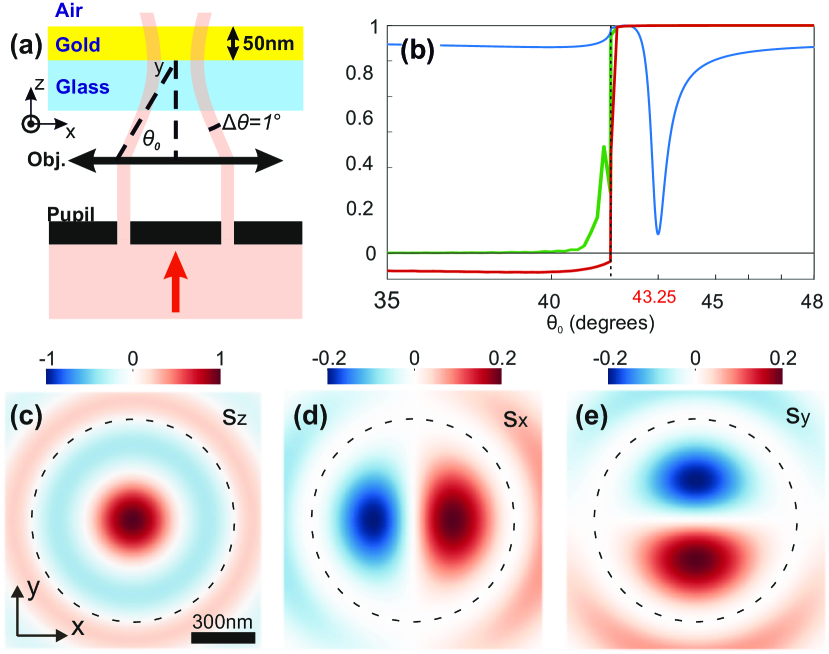
The calculations were conducted at a wavelength of nm. We identified a surface plasmon excitation at an incidence angle of 43.25∘ (following the Kretschmann configuration; see Fig. 1(b)). Figure 1(b-e) shows an analysis of the vector spin structure generated at a distance of 10 nm beyond the gold film’s upper interface by focusing RPVB and CPB. With a skyrmion number of 1 beyond the critical angle of 41.8∘ (Fig. 1(b)), the photonic spin structures generated at plasmon resonance by both beams are an optical analogue to a magnetic skyrmion. The radially-distributed spin texture observed in Figs. 1(c-e) for the RPVB identifies a plasmonic Neel skyrmion. A similar spin texture is obtained for circular polarization. Outside the plasmon resonance, below the critical angle, the SAM texture transitions to an azimuthally polarized state, akin to the magnetization texture observed in Bloch skyrmions. The skyrmion number is however insufficient to categorize the optical field as an optical analogue to the Bloch skyrmion.
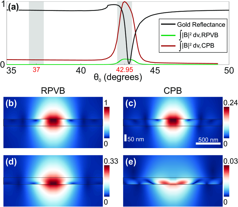
Fig. 2 shows the optomagnetic response of the thin gold film upon illumination with focused RPVB and CPB, with . Upon scanning the average incidence angle, the total optomagnetic energy (defined in the inset of Fig. 2(a)) peaks right at the plasmon angle for both incident polarization states, coinciding with the minimum optical reflectance (Fig. 2(a)). At surface plasmon excitation, the optomagnetic energy is enhanced by approximately 13-fold and 128-fold for RPVB and CPB, respectively. This confirms the role of surface plasmons in amplifying optomagnetism in metals. However, despite their common skyrmion nature at plasmon resonance, the transmitted fields obtained with the RPVB and CPB result in distinct levels of optomagnetism: the optomagnetic energy is 11.5 times larger with the plasmonic Neel-type skyrmion produced by the RPVB.
Fig. 2(b) and (c) show the optomagnetic field generated when a plasmonic Neel skyrmion is applied to the thin gold film. Using the focused RPVB (Fig. 2(b)), the maximum optomagnetic field is localized at the upper surface of the gold film, at the surface plasmon resonance. Off-resonance (Fig. 2(d)), the optomagnetic field is confined at the lower interface with its maximum reduced by a factor of 3. As a comparison, the optomagnetic fields generated on and off plasmon resonance with the focused CPB are attenuated by 4 and 30 times, respectively (see Figs. 2(c) and 2(e), respectively). The optomagnetic fields obtained at plasmon resonance for both polarizations show similar spatial distributions (Figs. 2(b) and (c)). A similar morphology of optomagnetic field remains off-resonance for the RPVB (cf. Figs. 2(b) and (d)), but is lost with the CPB (cf. Figs. 2(c) and (e)).
According to Eqs. 1 and 2, a focused RPVB generates an axis-symmetrical ” optical state” within the metal film, which is constituted of -polarized Fourier components. In contrast, when a focused CPB is applied, a combination of axis-symmetrical and optical states arises within the metal film (see Eqs. 1, 3 and 4). The ” optical state”, constituted of -polarized Fourier components, is primarily confined within the skin depth at the lower interface.
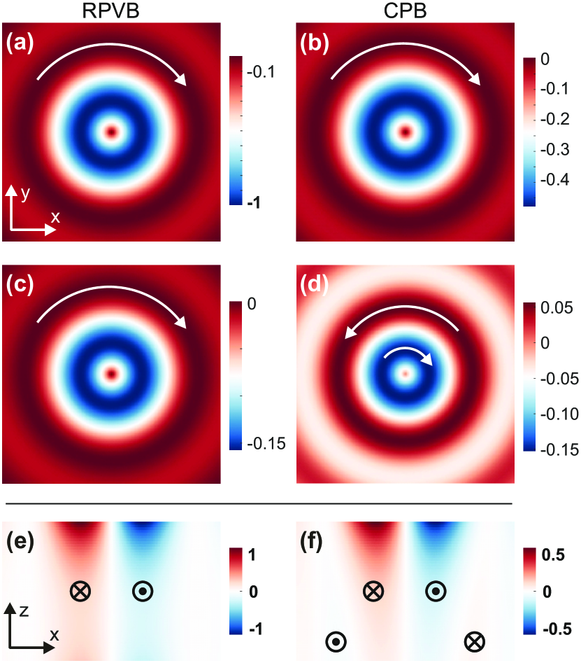
In the case of the RPVB, the entirety of the incident field intensity contributes to the generation of the optical state within the metal film, which includes surface plasmons (cf. Eq 2). By comparing Eqs. 2 and 3, we see that only half of the incident field intensity is involved for circular polarization. As the surface and volume current densities stem from a second-order nonlinear optical effect (see Eqs. 9 and 10) [27], the plasmonic Neel skyrmion produced with the RPVB exhibits twice the efficiency in generating opto-induced drift currents compared to the one obtained with the CPB, as shown in Fig. 3. Since the optical state is confined within the lower skin depth, the plasmon-induced drift current densities exhibit similar spatial distributions in the upper half of the gold film, as shown in Figs. 3(a,b) and 3(e,f). However, circular polarization results in a maximum amplitude of the drift current densities that is halved.
With the focused RPVB, the plasmonic Neel skyrmion generates surface and volume drift current densities of the same handedness, forming a uniform current loop (see Figs. 3(a,c,e)). In contrast, the presence of a optical state with the CPB induces a pair of current loops with opposite handedness in the lower half of the metal film, which is less efficient in generating an optomagnetic field (Figs. 3(d,f)). Therefore, the existence of optical states in the plasmonic film both attenuates amplitude of the plasmon field and hinders the optomagnetic effect in the lower half of the metal film. As a result, in our study, the optomagnetic field is reduced by four with the focused CPB compared to the focused RPVB (which lacks optical state), although an optical Neel skyrmion is transmitted through the metal film in both cases. Therefore, by creating a pure optical state in a thin gold film, the plasmonic Neel skyrmion obtained with the RPVB emerges as an optimum for generating plasmon-induced magnetism.
To conclude, an optical counterpart of magnetic Neel skyrmion is shown to generate a static magnetic field in a thin gold film, via plasmon-enhanced IFE. We evidence that circular polarization, the standard for producing IFE, is not the optimal choice for inducing plasmon-enhanced optomagnetism in a thin gold film. The optimum is achieved with a plasmonic Neel skyrmion obtained from a vector vortex beam. Vector vortex beams, which produce optical skyrmions by exploiting spin-orbit interaction, open new avenues for generating and controlling plasmon-induced magnetism in metal films, and by extension, in resonant plasmonic nanoantennas.
Funding
EIPHI Graduate School (contract ANR-17-EURE-0002); Region ”Bourgogne Franche-Comte”; French Agency of Research (contracts ANR-18-CE42-0016 and ANR-23-CE42-0021); French Renatech network; Equipex+ Nanofutur (21-ESRE-0012)
Disclosures
The authors declare no conflicts of interest.
References
- [1] Albert Fert, Vincent Cros and Joao Sampaio “Skyrmions on the track” In Nature nanotechnology 8.3 Nature Publishing Group UK London, 2013, pp. 152–156
- [2] Sebastian Muhlbauer et al. “Skyrmion lattice in a chiral magnet” In Science 323.5916 American Association for the Advancement of Science, 2009, pp. 915–919
- [3] A Neubauer et al. “Topological Hall effect in the A phase of MnSi” In Physical review letters 102.18 APS, 2009, pp. 186602
- [4] C Pappas et al. “Chiral paramagnetic skyrmion-like phase in MnSi” In Physical review letters 102.19 APS, 2009, pp. 197202
- [5] S Tsesses et al. “Optical skyrmion lattice in evanescent electromagnetic fields” In Science 361.6406 American Association for the Advancement of Science, 2018, pp. 993–996
- [6] Luping Du, Aiping Yang, Anatoly V Zayats and Xiaocong Yuan “Deep-subwavelength features of photonic skyrmions in a confined electromagnetic field with orbital angular momentum” In Nat. Phys. 15.7 Nature Publishing Group, 2019, pp. 650–654
- [7] Xinrui Lei et al. “Photonic spin lattices: symmetry constraints for skyrmion and meron topologies” In Phys. Rev. Lett. 127.23 APS, 2021, pp. 237403
- [8] PS Pershan, JP Van der Ziel and LD Malmstrom “Theoretical discussion of the inverse Faraday effect, Raman scattering, and related phenomena” In Physical review 143.2 APS, 1966, pp. 574
- [9] Daria Popova, Andreas Bringer and Stefan Blügel “Theory of the inverse Faraday effect in view of ultrafast magnetization experiments” In Phys. Rev. B 84.21 APS, 2011, pp. 214421
- [10] Riccardo Hertel “Theory of the inverse Faraday effect in metals” In J. Magn. Magn. Mater. 303.1 Elsevier, 2006, pp. L1–L4
- [11] E Beaurepaire, J-C Merle, A Daunois and J-Y Bigot “Ultrafast spin dynamics in ferromagnetic nickel” In Phys. Rev. Lett. 76.22 APS, 1996, pp. 4250
- [12] CD Stanciu et al. “All-optical magnetic recording with circularly polarized light” In Phys. Rev. Lett. 99.4 APS, 2007, pp. 047601
- [13] Andrei Kirilyuk, Alexey V Kimel and Theo Rasing “Ultrafast optical manipulation of magnetic order” In Rev. Mod. Phys. 82.3 APS, 2010, pp. 2731
- [14] AV Kimel et al. “Ultrafast non-thermal control of magnetization by instantaneous photomagnetic pulses” In Nature 435.7042 Nature Publishing Group, 2005, pp. 655–657
- [15] AM Kalashnikova et al. “Impulsive excitation of coherent magnons and phonons by subpicosecond laser pulses in the weak ferromagnet FeBO 3” In Phys. Rev. B 78.10 APS, 2008, pp. 104301
- [16] Takuya Satoh et al. “Directional control of spin-wave emission by spatially shaped light” In Nat. Photonics 6.10 Nature Publishing Group, 2012, pp. 662–666
- [17] IV Savochkin et al. “Generation of spin waves by a train of fs-laser pulses: a novel approach for tuning magnon wavelength” In Sci. Rep. 7.1 Nature Publishing Group, 2017, pp. 1–10
- [18] Keita Matsumoto et al. “Observation of evanescent spin waves in the magnetic dipole regime” In Phys. Rev. B 101.18 APS, 2020, pp. 184407
- [19] Igor I Smolyaninov et al. “Plasmon-induced magnetization of metallic nanostructures” In Phys. Rev. B 71.3 APS, 2005, pp. 035425
- [20] Yu Gu and Konstantin G Kornev “Plasmon enhanced direct and inverse Faraday effects in non-magnetic nanocomposites” In JOSA B 27.11 Optical Society of America, 2010, pp. 2165–2173
- [21] Oscar Hsu-Cheng Cheng, Dong Hee Son and Matthew Sheldon “Light-induced magnetism in plasmonic gold nanoparticles” In Nat. Photon. 14.6 Nature Publishing Group, 2020, pp. 365–368
- [22] KL Koshelev, V Yu Kachorovskii and M Titov “Resonant inverse Faraday effect in nanorings” In Phys. Rev. B 92.23 APS, 2015, pp. 235426
- [23] SM Hamidi, M Razavinia and MM Tehranchi “Enhanced optically induced magnetization due to inverse Faraday effect in plasmonic nanostructures” In Opt. Commun. 338 Elsevier, 2015, pp. 240–245
- [24] Athavan Nadarajah and Matthew T Sheldon “Optoelectronic phenomena in gold metal nanostructures due to the inverse Faraday effect” In Opt. Express 25.11 Optical Society of America, 2017, pp. 12753–12764
- [25] Jérôme Hurst, Peter M Oppeneer, Giovanni Manfredi and Paul-Antoine Hervieux “Magnetic moment generation in small gold nanoparticles via the plasmonic inverse Faraday effect” In Phys. Rev. B 98.13 APS, 2018, pp. 134439
- [26] Ritwik Mondal et al. “Relativistic interaction Hamiltonian coupling the angular momentum of light and the electron spin” In Phys. Rev. B 92.10 APS, 2015, pp. 100402
- [27] Vage Karakhanyan, Yannick Lefier, Clément Eustache and Thierry Grosjean “Optomagnets in nonmagnetic plasmonic nanostructures” In Opt. Lett. 46.3 OSA, 2021, pp. 613–616 DOI: 10.1364/OL.411108
- [28] Vage Karakhanyan, Clément Eustache, Yannick Lefier and Thierry Grosjean “Plasmon-induced 0.13 T optomagnetic field in a gold coaxial nanoaperture” In OSA Continuum 4.5 OSA, 2021, pp. 1598–1608 URL: http://www.osapublishing.org/osac/abstract.cfm?URI=osac-4-5-1598
- [29] Alan Hwader Chu et al. “Hybrid magneto photonic material structure for plasmon assisted magnetic switching” In Opt. Mat. Express 10.12 Optical Society of America, 2020, pp. 3107–3118
- [30] DO Ignatyeva et al. “Plasmonic layer-selective all-optical switching of magnetization with nanometer resolution” In Nat. Commun. 10.1 Nature Publishing Group, 2019, pp. 1–7
- [31] Song-Jin Im et al. “All-optical magnetization switching by counterpropagataion or two-frequency pulses using the plasmon-induced inverse Faraday effect in magnetoplasmonic structures” In Phys. Rev. B 99.4 APS, 2019, pp. 041401
- [32] Feng Cheng et al. “All-Optical Manipulation of Magnetization in Ferromagnetic Thin Films Enhanced by Plasmonic Resonances” In Nano Lett. 20.9 ACS Publications, 2020, pp. 6437–6443
- [33] Vage Karakhanyan, Clément Eustache, Yannick Lefier and Thierry Grosjean “Inverse Faraday effect from the orbital angular momentum of light” In Physical Review B 105.4 APS, 2022, pp. 045406
- [34] Luping Du, Aiping Yang, Anatoly V Zayats and Xiaocong Yuan “Deep-subwavelength features of photonic skyrmions in a confined electromagnetic field with orbital angular momentum” In Nature Physics 15.7 Nature Publishing Group UK London, 2019, pp. 650–654
- [35] Xiang Hao, Cuifang Kuang, Tingting Wang and Xu Liu “Phase encoding for sharper focus of the azimuthally polarized beam” In Optics letters 35.23 Optical Society of America, 2010, pp. 3928–3930
- [36] Zhe Zhao, Jian Wang, Shuhui Li and Alan E Willner “Metamaterials-based broadband generation of orbital angular momentum carrying vector beams” In Optics letters 38.6 Optical Society of America, 2013, pp. 932–934
- [37] Cheng-Wei Qiu et al. “Engineering light-matter interaction for emerging optical manipulation applications” In Nanophotonics 3.3 De Gruyter, 2014, pp. 181–201
- [38] Bernard Richards and Emil Wolf “Electromagnetic diffraction in optical systems, II. Structure of the image field in an aplanatic system” In Proceedings of the Royal Society of London. Series A. Mathematical and Physical Sciences 253.1274 The Royal Society London, 1959, pp. 358–379
- [39] Lukas Novotny and Bert Hecht “Principles of nano-optics” Cambridge university press, 2012
- [40] Max Born and Emil Wolf “Principles of optics: electromagnetic theory of propagation, interference and diffraction of light” Elsevier, 2013
- [41] Konstantin Y Bliokh, Daria Smirnova and Franco Nori “Quantum spin Hall effect of light” In Science 348.6242 American Association for the Advancement of Science, 2015, pp. 1448–1451
- [42] Michael V Berry “Optical currents” In J.Opt. A 11.9 IOP Publishing, 2009, pp. 094001
- [43] Konstantin Y Bliokh, Aleksandr Y Bekshaev and Franco Nori “Extraordinary momentum and spin in evanescent waves” In Nat. Commun. 5.1 Nature Publishing Group UK London, 2014, pp. 3300
- [44] Sandip Bera and Sudhansu S Mandal “Theory of the skyrmion, meron, antiskyrmion, and antimeron in chiral magnets” In Physical Review Research 1.3 APS, 2019, pp. 033109
- [45] XZ Yu et al. “Transformation between meron and skyrmion topological spin textures in a chiral magnet” In Nature 564.7734 Nature Publishing Group UK London, 2018, pp. 95–98