Robot Safety Monitoring using Programmable Light Curtains
Abstract
As factories continue to evolve into collaborative spaces with multiple robots working together with human supervisors in the loop, ensuring safety for all actors involved becomes critical. Currently, laser-based light curtain sensors are widely used in factories for safety monitoring. While these conventional safety sensors meet high accuracy standards, they are difficult to reconfigure and can only monitor a fixed user-defined region of space. Furthermore, they are typically expensive. Instead, we leverage a controllable depth sensor, programmable light curtains (PLC), to develop an inexpensive and flexible real-time safety monitoring system for collaborative robot workspaces. Our system projects virtual dynamic safety envelopes that tightly envelop the moving robot at all times and detect any objects that intrude the envelope. Furthermore, we develop an instrumentation algorithm that optimally places (multiple) PLCs in a workspace to maximize the visibility coverage of robots. Our work enables fence-less human-robot collaboration, while scaling to monitor multiple robots with few sensors. We analyze our system in a real manufacturing testbed with four robot arms and demonstrate its capabilities as a fast, accurate, and inexpensive safety monitoring solution.
I Introduction
Despite several advances in factory automation using robots, human operators are still required during the manufacturing process for operations that involve unpredictable behavior (e.g., fabric, rubber) or fine-tuned sensitivity (e.g., electronics assembly). To enable seamless collaboration between humans and robots in manufacturing processes, it is necessary to develop robust safety systems that protect the collaborative environment and optimize the overall production cycle [3, 4]. Such systems should incorporate advanced sensors, intelligent perception and control algorithms, and clear communication protocols.
Current safety systems can be broadly categorized into two approaches — (1) fixed barriers and (2) vision-based collision avoidance [5, 6]. Fixed barriers, such as fences, fixed light curtains, and time-of-flight (ToF) sensors, physically demarcate the robot’s workspace and isolate it from human activity. While fixed barriers are simple to construct or implement, and are computationally efficient, they limit collaborative work and reduce flexibility and performance in shared spaces (e.g., they prevent the robot from crossing the barrier even if no obstacle is present). Other collision avoidance approaches utilize vision systems such as cameras [7], LiDARs [8], and 3D time-of-flight sensors [9, 10] to dynamically adapt the robot’s behavior based on its surroundings. This enables a higher degree of collaboration and flexibility but typically require multiple devices and powerful computational resources (multi-core CPUs and GPUs) for processing the raw sensor streams.
Programmable light curtains (PLCs) [11, 1] are a recently developed controllable 3D sensor that images points only along a user-specified ruled surface (called a ‘curtain’). These curtains, which are projected by a steerable sheet laser, can be adapted in real-time to image desired objects or regions of interest at a high resolution. The sensor has an ideal working range of up to meters, is robust even in the presence of ambient light, and is relatively inexpensive (the lab-built prototype costs about K - K). Prior works have successfully used PLCs for various tasks in robotics such as object detection [2], depth estimation [12], navigation [13], and safety envelope estimation [14].
In this work, we use PLCs to build a flexible safety monitoring system for industrial robots. PLCs are used to detect the presence or absence of objects around robots by creating virtual ‘safety curtains’ that tightly envelop the robot and adapt to the robot’s configuration as it moves. When an obstacle penetrates the safety curtain, the intrusion is detected and the robot is immediately commanded to stop. Simultaneously, we also use light curtains to scan the scene and produce a dense 3D reconstruction of the workspace. In addition, we show how PLCs can be optimally placed i.e. “instrumented” in the workspace to maximize the visibility coverage of the robots. The resulting system is relatively inexpensive compared to traditional laser-based safety systems ($K-K vs $K-K). Furthermore, a single PLC can monitor multiple robots within its field-of-view. Therefore, our method easily scales to many robots using only few PLCs sensors.
In this paper, we make the following contributions towards building a PLC-based safety monitoring system:
-
•
We develop an optimization procedure to best position (instrument) multiple PLCs in a workspace to maximize visibility coverage of a given set of robots (Sec. IV-A).
- •
-
•
We show how safety curtains can be interleaved with curtains that sweep across the scene to produce high-resolution 3D scene reconstructions (Sec. IV-D).
-
•
We evaluate our safety system in a real-world manufacturing testbed environment to monitor four robot arms using two PLCs. We evaluate the accuracy of our system to detect various object types, and conduct a detailed analysis of its latency and response time to safely stop a robot under intrusion (Sec. V).
II Related Work
Technology Cost Response time Power consumption Compute Needs Program- mability Multi Beam LiDAR [15] $$$ ms W High High 3D ToF [9, 10] $$ ms W-kW High High Cameras [7, 16, 17] $ ms -W High High Ultrasonic Sensors [18, 19] $ - ms W Low Low Fixed light curtains [20] $$ - ms W Low Low Prog. light curtains (Ours) $ - ms W Low High
II-A Robot Safety Monitoring
Conventional methods for safety monitoring designate a fixed robot workspace.
Human workers are prevented from intruding this workspace either using physical fence barriers or fixed light curtains [20].
As robot environments become increasingly collaborative, there is a need for adaptive vision-based systems.
Table I summarizes prior technologies that can be used for robot safety monitoring in collaborative workspaces. Some advanced methods such as LiDAR [15, 21], cameras [7, 16, 17, 22] and 3D time-of-flight (ToF) sensors [9, 10] provide high programmability but require heavy compute and power resources.
In systems involving LiDAR, RGB(D) cameras, or 3D ToF sensors, there’s a need for significant processing. These systems have to separate intrusions from the image/point cloud and/or use object detection models. For example, with 3D ToF, processing is necessary to identify the robot workspace, detect moving objects, and calculate the minimum distance between them to decide on actions like stopping or slowing down. Additionally, using multiple cameras to capture and merge point clouds adds to the power and computational requirements.
While relatively simpler solutions such as ultrasonic sensors [18, 19] and fixed light curtains have the potential to provide low latencies and low power systems, they are not programmable. Vogel et al. [23] conceptualized a programmable safety system using a visible-light projector and camera, but without a real implementation using robots. The safety system presented and implemented in this paper provides a highly programmable and accurate solution, requires minimal computation, and provides a low response time while keeping the overall cost low.
II-B Programmable Light Curtains
PLC was first introduced in [11, 1] as a controllable depth sensor that can sense along any vertically-ruled surface at high-resolution. Chan et. al. [24] recently upgraded the sensor to be able to sense along any arbitrary-shaped 2D surface using a holographic projector. We use the original sensor, based on a line laser and rolling-shutter camera, in our setup as it can adapt its sensing surface in real-time.
Prior works have used PLCs for perception tasks such as 3D object detection[2] and monocular depth sensing [12]. Ancha et. al. [25] used PLCs for computing dynamic safety envelopes in unknown environments, which is closest to our work. Ancha et. al. [13] extended light curtains for velocity estimation of dynamic obstacles in unknown environments. The aforementioned tasks fall in the category of active perception where the next light curtain to be placed depends on previous sensor measurements. Our work differs from active perception by focusing on the specific setting of indoor safety monitoring for manufacturing robots where the positions and motion of robots are known apriori. This removes the need for active sensing and forecasting for curtain placement, while also increasing the need for real-time tracking with high accuracy.
III Background on Prog. Light Curtains
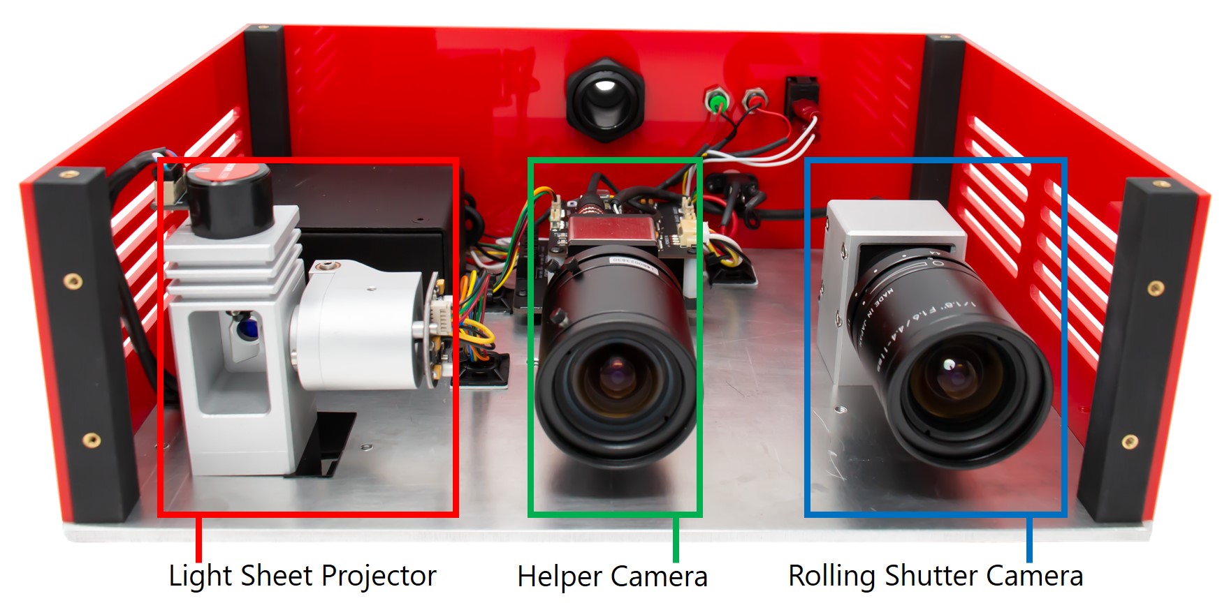
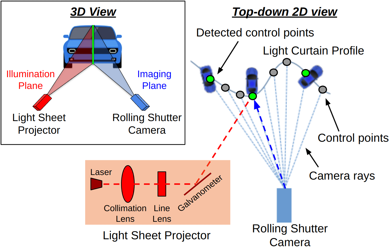
Programmable light curtains (PLCs) [11, 1] are a recently-developed controllable depth sensor that images only along a specified vertically-ruled 2D surface in the environment. The sensor contains two main components: a rolling-shutter near-infrared (NIR) camera and a rotating sheet NIR laser (see 1(a)). The rolling-shutter camera activates one pixel column at a time, and we refer to the top-down projection of the imaging plane corresponding to each pixel column as a “camera ray” (see 7(c)). A 2D control point is selected on each camera ray (shown as gray and green circles). A controllable galvo-mirror rotates the laser light sheet in synchrony with the rolling shutter camera to point the laser sheet at the control point corresponding to the currently active pixel column. 3D scene points that lie at the surface of this intersection between the projected light sheet and the image plane (called ‘curtain’) get imaged by the camera (shown as green circles). The set of control points completely determine the shape of the light curtain and subsequently the objects that are imaged. These control points form the input to the PLC. The control points can be specified at each timestep to place a curtain in each imaging iteration of the camera. Additionally, an RGB camera is used as a ‘helper camera’ to visualize the projected light curtains as shown in LABEL:fig:teaser. Please refer to Bartels et. al. [1] for more details about PLCs such as its hardware specification and performance under various lighting conditions.
IV Method
In this work, we study the problem of building an inexpensive safety monitoring system using PLCs. Towards this goal, we first address the question of how to place (i.e. instrument) the sensors in the robot workspace or factory floor to maximize the safety coverage of the robots. Then, we discuss how to design the shape of the projected light curtains so that they can act as a dynamic ‘safety shield’ around the robot and detect object intrusions. Finally, we discuss how the PLCs can be used to obtain a full 3D reconstruction of the workspace.
IV-A PLC instrumentation to maximize robot coverage
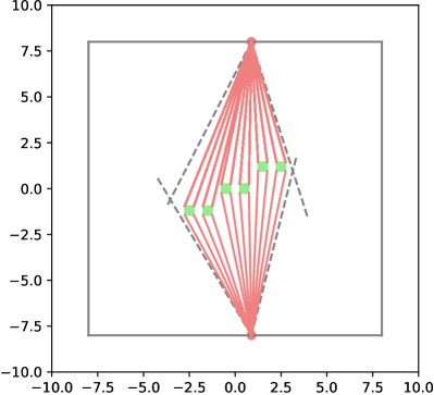
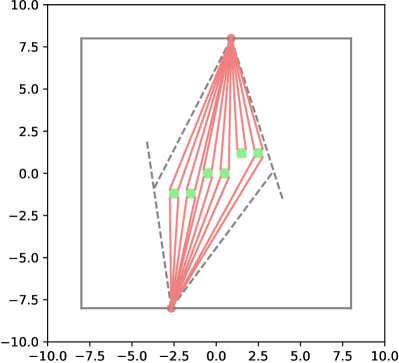
For a given layout and positions of robot arms in a work-space, we begin by determining the optimal positions and orientations of the PLCs that can safely envelope all the robots. Instead of manually specifying the positions and orientations guided by intuition or trial-and-error, we take a principled algorithmic approach as follows.
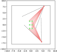
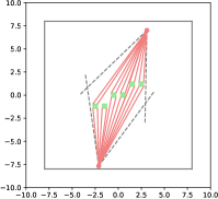
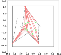
We represent each robot and PLC in D from the top-down view, as shown in Fig. 2. Each robot is represented by a -sided polygon (shown in green), and the location of the PLC device is represented by a point (shown as red circles). The four vertices of each robot polygon are provided as input to our algorithm and remain fixed, while the D pose () of each PLC needs to be estimated. The continuous search space for 2D pose is reduced to a discretized grid of poses.
Naïve brute-force search over this grid yields an exponential time-complexity of , where is the number of discretized , and values searched over, and is the number of PLCs. The computationally complexity is prohibitively large. Instead, our approach is to generate uniformly random samples from this search space, inspired by RANSAC [26].
After we sample a D pose for each PLC, we determine the robots contained within each PLC’s field-of-view. For every robot within the field-of-view, we compute the angle subtended by the edge formed by the two closest vertices of the robot polygon at the PLC. Importantly, we only consider a vertex if it has not already been observed by another PLC in order to avoid double-counting the coverage of the robot.
The sum of angles subtended by the observed edges at every PLC is used as a measure of coverage quality for every sampled configuration. Higher scores are given to configurations where all vertices of a robot are covered. We repeat this process for each of the sampled PLC configurations and return the configuration with the highest sum of subtended angles. The number of PLCs required to completely envelope all robot edges can be determined by simply running the algorithm for an increasing number of PLCs, starting from 2, until all the visible edges of the robots are covered. The full algorithm is described in Alg. 1.
IV-B Safety curtain design
We design safety curtains from each PLC based on the known poses of the robot arms in the scene. For this, we first obtain the joint positions from the robot arms’ joint encoders, compute their 3D locations using forward kinematics, and then project them into the 2D top-down view in the frame of reference of the closest PLC. Since the number of joint positions are usually small (-), we also use the positions of some pre-defined virtual joints from the robot’s geometry. We then compute a 2D convex hull in the 2D top-down view enclosing all of the 2D robot points using the Quickhull algorithm [27]. Finally, to compute the control points of the curtain, we perform 2D ray-tracing for each camera ray of the PLC in the 2D plane containing the convex hull. The points of intersections of each ray with the hull determine the control points and hence the shape of the safety curtain. A small additional offset is added to the control points to ensure the curtains don’t intersect with the robots while being sufficiently close to the robot’s surface. This computation is repeated at each time step as each robot moves around its workspace, ensuring that the safety curtains dynamically adapt and closely track the robots’ motion in real-time.
IV-C Intrusion Detection
If an object intersects the safety curtain, it is detected as a high-intensity return on the raw image of the PLC. Once an object detection is observed, we determine which robot(s) it corresponds to based on the 3D location of the detection. This robot is then instructed to stop immediately. Interference from other sensors may also occasionally cause intensity returns. Since these interference returns can usually last between 2 to 4 frames, we stop a robot only if there is a continuous intensity return for more than 4 consecutive frames. In situations where utmost safety is prioritized over efficiency, the robots can be temporarily stopped whenever an intensity return is received, regardless of whether it originates from an object or interference. Additionally, detections due to interference exhibit a distinct pattern. One direction of future work could be to train a small on-device neural network to determine if the intensity return is caused by interference or an object.
IV-D Scene Reconstruction
In addition to placing safety curtains, we also obtain high-resolution depth maps by sweeping the scene with fixed-shape (or random) curtains. We merge the points detected by each curtain in the sweep to output a full depth reconstruction. Each intensity return has an associated depth map as each pixel corresponds to a known camera-ray – laser sheet intersection. These intensity returns from a full sweep can then be merged together into a single intensity image by storing the maximum intensity value at each pixel location across the sweep of images. This merged intensity image is then backprojected to a full 3D point cloud using the known depth value and the camera’s intrinsics. Since the PLC can project multiple light curtains at the camera’s frame rate of - Hz, random curtains (meant for reconstruction) can be interleaved with the safety curtains (meant for collision avoidance). The point clouds generated from each sensor are sent to a workstation where they are processed and registered together using the iterative closest point (ICP) algorithm [28]. The resulting 3D map of the static environment could be further used to detect other dynamic objects such as mobile robots or people navigating in the workspace.
V Experiments
V-A Setup
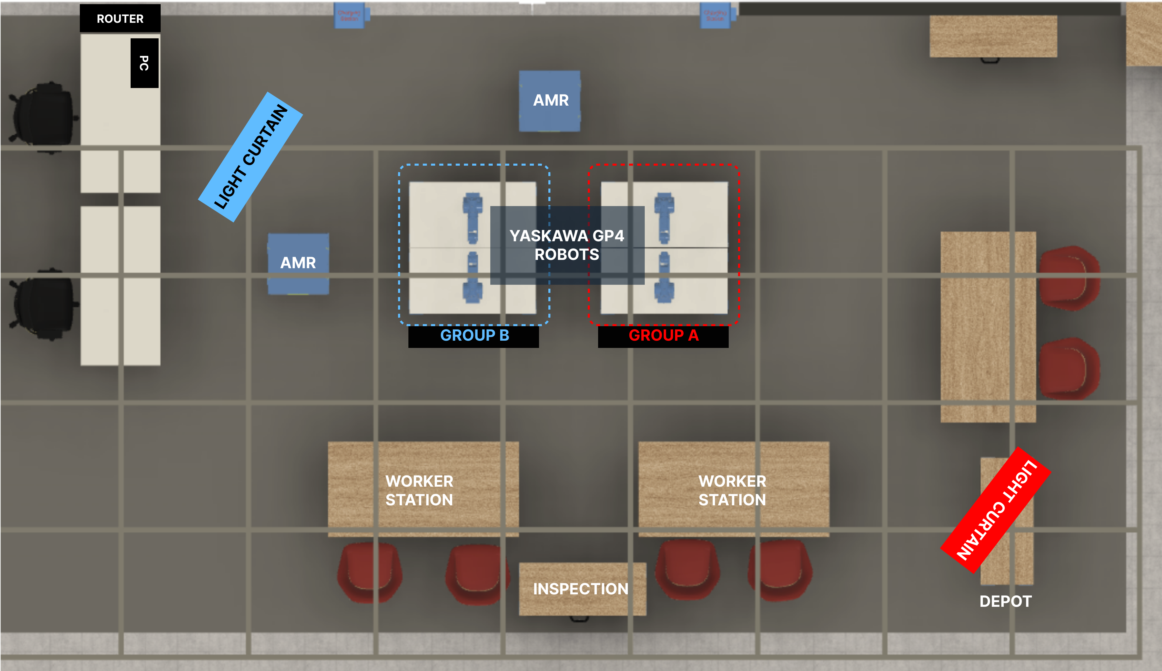
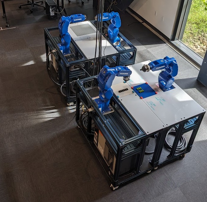
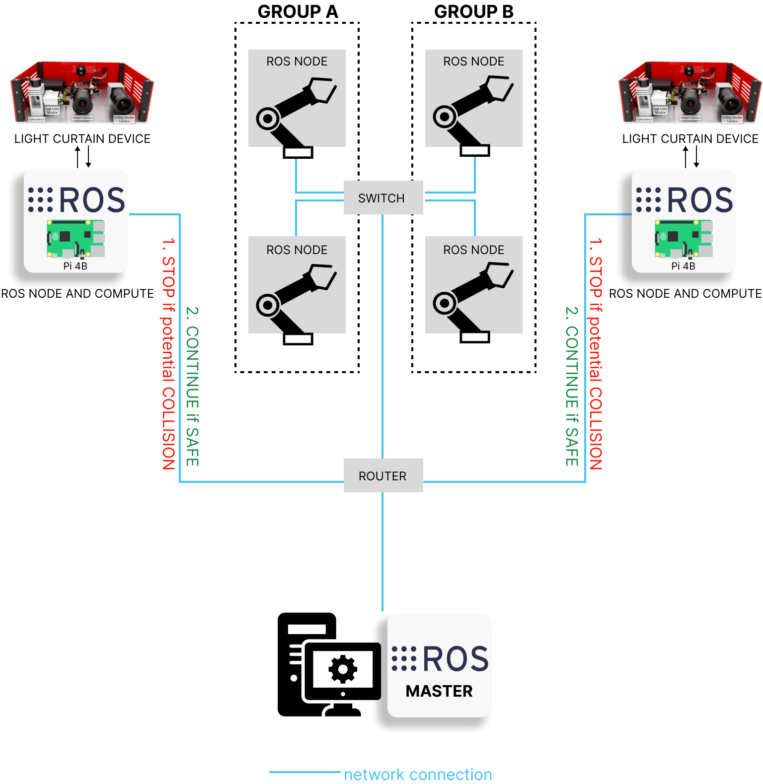
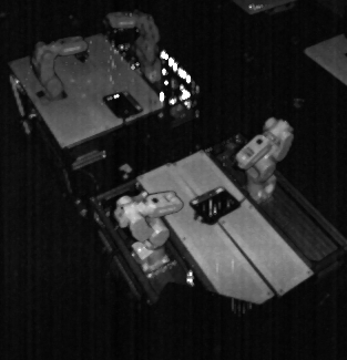
Testbed: We demonstrate the capabilities of our safety monitoring system in a manufacturing testbed shown in Fig. 3. The testbed consists of two pairs of Yasakawa® GP4 robotic arms arranged in a square layout, with each pair collaborating to assemble and disassemble a Lego® model. Each robot is equipped with its own control PC which is also connected to a central workstation over ROS. There are two autonomous mobile robots (AMRs) that move material between the arm robots and the worker stations. We mount two downward-facing PLCs on a / grid attached to the ceiling at a height of m from the ground. Each PLC has a Raspberry-Pi® 4 onboard which executes the code for designing and imaging the light curtains. Including the RPi, each PLC draws up to 10W power. The dimensions of the testbed are m2 and all inter-process communication is carried over Ethernet to minimize latency. The pose between each robot and PLC is calibrated with an eye-on-base calibration procedure using Apriltags [29]. Due to the high engineering effort and/or cost of implementing other safety systems in the testbed, we limit our experiments and analysis to only our system.
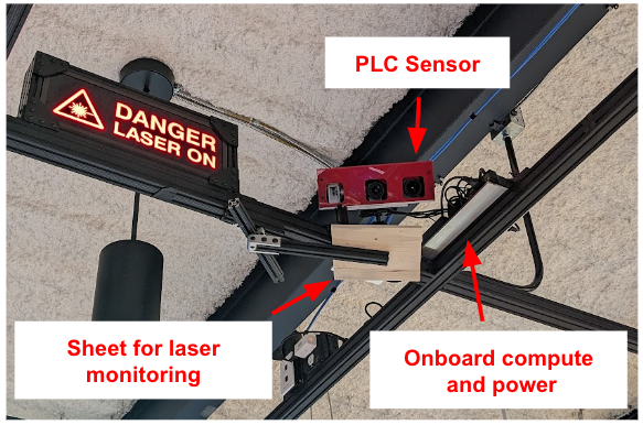
Eye Safety: Eye safety requirements limit the maximum power at which the laser on the PLC can be operated [30, 31], which limits the maximum range of the sensor. In our testbed, we operate the laser at 30% of its maximum power (1W), which corresponds to a maximum eye-safe distance of 16.80 cm. This distance is well beyond the reach of people (with a height of at-most 9 feet) during regular operation. As further precaution, we also monitor the output of the sensor to ensure that the galvanometer mirror is rotating and that the laser’s power level is maintained. We do so by attaching a white planar sheet as an extension to the sensor at a short distance within its field-of-view (shown in Fig. 5) without introducing any additional circuitry into the prototype sensor. This sheet is scanned by the PLC every second and if the intensity return from it does not match the expected return, the mirror is deemed malfunctioning and the sensor is immediately turned off. The returned intensity values are also monitored to ensure that the laser’s output power is constant and is not fluctuating.
V-B Results
Instrumentation: The two PLCs in our testbed are positioned according to results from our algorithm described in Sec. IV-A. Unlike regular laser-based safety sensors that typically can monitor only one robot each, our two PLCs can monitor all four robots as well as the full workspace area for people and other mobile robots.
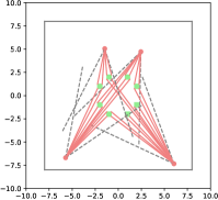
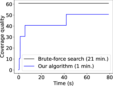
We provide additional results of our algorithm on four robot layouts (grid, staggered, randomized, octagon) in Fig. 6. The algorithm was run on a grid size of for iterations and took approximately minutes for each layout on a single Intel Xeon W2123 CPU core. It was run for iterations on the octagon layout with PLCs which took about hours to complete. We consider a robot to be fully enveloped if all its four corners are observable. Clearly, the layout of the robots determines the number of PLCs required to safely envelope all the robots. 6(b) shows that the more staggered the robots are, the fewer is the number of PLCs required. We also compare our algorithm against a brute-force search approach, on a smaller search grid of , in Fig. 7. Our algorithm approaches the performance of brute-force search in a significantly smaller amount of time and scales easily to more number of PLCs and larger grid sizes.
Safety curtains: The blue and red PLCs receive the joint positions of the group A and group B robots respectively over ROS at Hz. These positions are used to compute, in real-time, the safety curtains required to envelope the robots in their current pose. The safety curtains are re-computed for every frame and projected to follow the robots’ movement, ensuring that the robots are always enveloped. This tracking behaviour of the sensors is visualized in the video on our website. Unlike regular laser-based safety systems which typically block the area around the robots, our safety curtains follow the robots more tightly which enables fence-less human-robot collaboration.
Intrusion detection: When a safety curtain intersects an object, the reflected laser light is captured directly by the NIR camera. These intrusions are detected at the optical level by design and are hence very accurate. Visualizations of such a detection are shown in LABEL:fig:teaser. Objects of varying sizes from a full-sized human to small parts of the hand can be quickly detected. For objects that are of dark colors, the laser operating power would need to be increased to detect them as dark objects tend to reflect a smaller fraction of incident light. When an intrusion is detected, the corresponding robot is immediately commanded to stop. The robot resumes its motion once the intruding object disappears. The accuracy of the setup was evaluated by throwing different sized objects into the robot’s workspace. We report the frequencies of detections in Table II.
| Objects | Detection frequency |
| Human Walking | 20 / 20 (100%) |
| Cap | 20 / 20 (100%) |
| Paper Ball | 18 / 20 (90%) |
| LEGO 4x2 Block | 15 / 20 (75%) |
![[Uncaptioned image]](/html/2404.03556/assets/images/objects.png)
Latency:
Apart from accuracy, the overall system response time is also important to ensure safety. The PLC sensor is fast and it can in principle operate at rates up to the imaging rate of the rolling-shutter camera (-Hz). In practice, it is limited by the time taken to compute the curtains, which varies according to the processor used. On the RPI-4 used in our setup, the imaging rate of the planar and random curtains is Hz (or response time of 42 ms). The imaging rate of the dynamic safety curtains that are designed and imaged according to the robot’s motion is Hz. The computationally expensive step is the ray-hull intersections, which implemented as unoptimized Python code takes ms on average on Raspberry Pi 4B. We quantify the latencies involved in the rest of the system by repeatedly projecting fixed planar curtains and recording the time taken for the robot to stop upon intrusion, over many trials. Results are reported in Table III. Like the imaging rate, the time taken to issue the STOP command can also be improved with a better processor (for e.g., ms on an i9 processor). The time taken for the robot to stop completely (approx. ms) is a limitation of the robot arm driver.
Event Time event occurs (fixed planar curtains) Time event occurs (dynamic safety curtains) Object intruded 0 ms 0 ms Intrusion detected 42 ms 143 ms STOP issued 91 ms 192 ms Robot stopped 374 ms 475 ms

3D Reconstruction: Apart from projecting safety curtains, the PLC sensors also sweep fixed-shape (planar) curtains at regular intervals ( cm) to obtain a full 3D reconstruction of the testbed area. The returned intensity images are merged into a single intensity image (shown in 9(a)) and its corresponding pointcloud reconstruction is obtained as described in Sec. IV-D. The pointclouds from both PLCs are then filtered and registered together using ICP on the central workstation with the calibrated poses of the PLCs used as initialization. The resulting pointcloud for the four robots is visualized in 9(b).
VI Conclusion
We presented a new inexpensive safety monitoring system using programmable light curtains for collaborative manufacturing. The system is flexible and can be used for monitoring arbitrary configurations of dynamic robots as well as the full 3D scene, while easily scaling to many robots. Future work would be to incorporate the robot motion plan and trajectory forecasting of obstacles into the pipeline to avoid recomputing safety curtains at each frame. Such forecasting would fully leverage PLC’s active sensing capabilities and enable new active safety monitoring systems that are able to pre-empt dangerous situations instead of responding passively. Likelihood-based sampling methods can be used to further speed-up the instrumentation search algorithm. Current limitations of the system include inaccurate depth sensing at large distances (greater than 8 m) due to curtain thickness [1] which can be alleviated using probabilistic depth models [12]. Another drawback is less sensitivity to dark objects, which could be alleviated by adapting the laser intensity online to the sensed objects.
Acknowledgements: This research is supported by the CMU Manufacturing Futures Institute, made possible by the Richard King Mellon Foundation. KR would like to thank Swaminathan Gurmurthy and Anurag Ghosh for helpful discussions.
References
- [1] J. R. Bartels, J. Wang et al., “Agile depth sensing using triangulation light curtains,” in Proceedings of the IEEE/CVF International Conference on Computer Vision, 2019, pp. 7900–7908.
- [2] S. Ancha, Y. Raaj et al., “Active perception using light curtains for autonomous driving,” in Computer Vision – ECCV 2020, A. Vedaldi, H. Bischof, T. Brox, and J.-M. Frahm, Eds. Cham: Springer International Publishing, 2020, pp. 751–766.
- [3] E. Matheson, R. Minto et al., “Human–robot collaboration in manufacturing applications: A review,” Robotics, vol. 8, no. 4, p. 100, 2019.
- [4] L. Gualtieri, E. Rauch, and R. Vidoni, “Emerging research fields in safety and ergonomics in industrial collaborative robotics: A systematic literature review,” Robotics and Computer-Integrated Manufacturing, vol. 67, p. 101998, 2021.
- [5] S. Robla-Gómez, V. M. Becerra et al., “Working together: A review on safe human-robot collaboration in industrial environments,” IEEE, vol. 5, pp. 26 754–26 773, 2017.
- [6] A. Buerkle, W. Eaton et al., “Towards industrial robots as a service (iraas): Flexibility, usability, safety and business models,” Robotics and Computer-Integrated Manufacturing, vol. 81, p. 102484, 2023.
- [7] M. Ozkahraman, C. Yilmaz, and H. Livatyali, “Design and validation of a camera-based safety system for fenceless robotic work cells,” Applied Sciences, vol. 11, no. 24, p. 11679, 2021.
- [8] K. Zheng, F. Wu, and X. Chen, “Laser-based people detection and obstacle avoidance for a hospital transport robot,” Sensors, vol. 21, no. 3, p. 961, 2021.
- [9] S. Pasinetti, C. Nuzzi et al., “Development and characterization of a safety system for robotic cells based on multiple time of flight (tof) cameras and point cloud analysis,” in 2018 Workshop on Metrology for Industry 4.0 and IoT. IEEE, 2018, pp. 1–6.
- [10] Intel, “Using intel® fpgas in veo freemove* system to enable safe, dynamic, and flexible human-robot collaboration,” 2020. [Online]. Available: https://www.intel.com/content/dam/www/central-libraries/us/en/documents/fpgas-in-veo-freemove-case-study.pdf
- [11] J. Wang, J. Bartels et al., “Programmable triangulation light curtains,” in Proceedings of the European Conference on Computer Vision (ECCV), 2018, pp. 19–34.
- [12] Y. Raaj, S. Ancha et al., “Exploiting & refining depth distributions with triangulation light curtains,” in Proceedings of the IEEE/CVF Conference on Computer Vision and Pattern Recognition, 2021, pp. 7434–7442.
- [13] S. Ancha, G. Pathak et al., “Active velocity estimation using light curtains via self-supervised multi-armed bandits,” in Proceedings of Robotics: Science and Systems, Daegu, Republic of Korea, July 2023.
- [14] S. Ancha, G. Pathak, S. Narasimhan, and D. Held, “Active Safety Envelopes using Light Curtains with Probabilistic Guarantees,” in Proceedings of Robotics: Science and Systems, Virtual, July 2021.
- [15] C. Altuntas, “Review of scanning and pixel array-based lidar point-cloud measurement techniques to capture 3d shape or motion,” Applied Sciences, vol. 13, no. 11, p. 6488, 2023.
- [16] S. Yang, W. Xu et al., “Multi-source vision perception for human-robot collaboration in manufacturing,” in 2018 ieee 15th international conference on networking, sensing and control (icnsc). IEEE, 2018, pp. 1–6.
- [17] A. Mohammed, B. Schmidt, and L. Wang, “Active collision avoidance for human–robot collaboration driven by vision sensors,” International Journal of Computer Integrated Manufacturing, vol. 30, no. 9, pp. 970–980, 2017.
- [18] J. Shepard, “Product detection and ranging using ultrasonic sensors.” [Online]. Available: https://www.digikey.com/en/articles/product-detection-and-ranging-using-ultrasonic-sensors
- [19] Z. Tong, H. Hu et al., “An ultrasonic proximity sensing skin for robot safety control by using piezoelectric micromachined ultrasonic transducers (pmuts),” IEEE Sensors Journal, vol. 22, no. 18, pp. 17 351–17 361, 2021.
- [20] “Safety Light Curtains | KEYENCE America.” [Online]. Available: https://www.keyence.com/products/safety/light-curtain/
- [21] D. Podgorelec, S. Uran et al., “Lidar-based maintenance of a safe distance between a human and a robot arm,” Sensors, vol. 23, no. 9, p. 4305, 2023.
- [22] M. J. Rosenstrauch, T. J. Pannen, and J. Krüger, “Human robot collaboration-using kinect v2 for iso/ts 15066 speed and separation monitoring,” Procedia CIRP, vol. 76, pp. 183–186, 2018.
- [23] C. Vogel, M. Poggendorf, C. Walter, and N. Elkmann, “Towards safe physical human-robot collaboration: A projection-based safety system,” in 2011 IEEE/RSJ International Conference on Intelligent Robots and Systems, 2011, pp. 3355–3360.
- [24] D. Chan, S. Narasimhan, and M. O’Toole, “Holocurtains: Programming light curtains via binary holography,” Computer Vision and Pattern Recognition, 2022.
- [25] S. Ancha, G. Pathak, S. Narasimhan, and D. Held, “Active safety envelopes using light curtains with probabilistic guarantees,” in Proceedings of Robotics: Science and Systems, Virtual, July 2021.
- [26] M. A. Fischler and R. C. Bolles, “Random sample consensus: a paradigm for model fitting with applications to image analysis and automated cartography,” Communications of the ACM, vol. 24, no. 6, pp. 381–395, 1981.
- [27] C. B. Barber, D. P. Dobkin, and H. Huhdanpaa, “The quickhull algorithm for convex hulls,” ACM Trans. Math. Softw., vol. 22, no. 4, p. 469–483, dec 1996. [Online]. Available: https://doi.org/10.1145/235815.235821
- [28] P. J. Besl and N. D. McKay, “Method for registration of 3-d shapes,” in Sensor fusion IV: control paradigms and data structures, vol. 1611. Spie, 1992, pp. 586–606.
- [29] M. Esposito et al., “Easy-handeye: Automated, hardware-independent hand-eye calibration for ros1.” [Online]. Available: https://github.com/IFL-CAMP/easy_handeye
- [30] S. Achar, J. R. Bartels et al., “Epipolar time-of-flight imaging,” ACM Trans. Graph., vol. 36, no. 4, jul 2017. [Online]. Available: https://doi.org/10.1145/3072959.3073686
- [31] A. N. S. Institute, American National Standard for Safe Use of Lasers, 2014. [Online]. Available: https://webstore.ansi.org/standards/lia/ansiz1362014