Hydroelectric energy conversion of waste flows through hydro-electronic drag
Abstract
Hydraulic energy is a key component of the global energy mix, yet there exists no practical way of harvesting it at small scales, from flows at low Reynolds number. This has triggered the search for alternative hydroelectric conversion methodologies, leading to unconventional proposals based on droplet triboelectricity, water evaporation, osmotic energy or flow-induced ionic Coulomb drag. Yet, these approaches systematically rely on ions as intermediate charge carriers, limiting the achievable power density. Here, we predict that the kinetic energy of small-scale "waste" flows can be directly and efficiently converted into electricity thanks to the hydro-electronic drag effect, by which an ion-free liquid induces an electronic current in the solid wall along which it flows. This effect originates in the fluctuation-induced coupling between fluid motion and electron transport. We develop a non-equilibrium thermodynamic formalism to assess the efficiency of such hydroelectric energy conversion, dubbed hydronic energy. We find that hydronic energy conversion is analogous to thermoelectricity, with the efficiency being controlled by a dimensionless figure of merit. However, in contrast to its thermoelectric analogue, this figure of merit combines independently tunable parameters of the solid and the liquid, and can thus significantly exceed unity. Our findings suggest new strategies for blue energy harvesting without electrochemistry, and for waste flow mitigation in membrane-based filtration processes.
Since its invention by Hero of Alexandria two thousand years ago, the turbine has been the tool of choice for converting the kinetic energy of a fluid flow into useful work. It is now a mature technology, with the hydroelectric conversion efficiency of modern turbines reaching over 90% Gordon (2001). However, turbines only function at macroscopic scales and with sufficiently fast flows. When the Reynolds number decreases below the turbulence transition, the turbine efficiency plummets Deam et al. (2008); Lemma et al. (2008). Thus, from an energetic standpoint, low Reynolds number flows are "waste flows", in the same way as temperatures below 100∘C are low-grade waste heat, still out of reach in terms of industrial energy recovery. Waste flows systematically arise in membrane-based filtration processes, as they involve liquids flowing through nanoscale pores McGinnis et al. (2007); Hu et al. (2010); Lin et al. (2014); Siria et al. (2017). The kinetic energy of these flows is either lost to friction with the pore walls or dumped with the concentrated feed solution, and harvesting it could mitigate the energetic cost of filtration. There also exist various strategies for converting industrial waste heat into liquid flow Barragán and Kjelstrup (2017); Pascual et al. (2023). Despite the ubiquity of waste flows, they have so far been converted to useful work only with limited efficiency.
Existing strategies are based on a wide range of astute physical principles, such as droplets impacts and triboelectricity Xie et al. (2014); Nie et al. (2019); Xu et al. (2020); Riaud et al. (2021), water evaporation Yang et al. (2017); Ding et al. (2017); Xue et al. (2017); Dao et al. (2020), or electrolyte flows along conductors Ghosh et al. (2003); Dhiman et al. (2011); Yin et al. (2014); Rabinowitz et al. (2020); Chen et al. (2023); Xiong et al. (2023), to name a few. Although diverse, these methodologies are rooted in the streaming of dissolved ions under the liquid flow, which – through the image charge effect – results in an electronic current in the contiguous conducting wall: an effect that has been termed "ionic Coulomb drag". These routes led to the design of small-scale energy generators, with various applications. However, their power-density remains overall limited, as well as difficult to scale up. In particular, ion polarization effects at membranes, and the charge imbalance associated with ion separation, are strong limitations to any ion-based energy conversion process Wang et al. (2022).
Ion-free hydrodynamic Coulomb drag
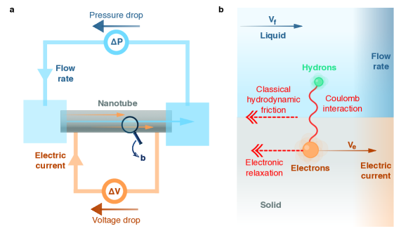
However, the use of ions as intermediate charge carriers to induce an electronic current is not necessarily a prerequisite. Indeed, on the basis of experimental observations and theoretical predictions, we showed recently Lizée et al. (2023); Coquinot et al. (2023a) that it is possible to directly convert the kinetic energy of a flowing liquid into an electronic current within the solid wall – a phenomenon dubbed hydrodynamic Coulomb drag Coquinot et al. (2023a); Lizée et al. (2023) or hydro-electronic drag. In the following, we adopt the latter denomination, to emphasize the distinction with the ionic Coulomb drag described above. At the root of hydro-electronic drag is the solid-liquid quantum friction phenomenon Kavokine et al. (2022a); Bui et al. (2023); Yu et al. (2023); Coquinot et al. (2023b); Kavokine et al. (2022b), where fluctuating interactions between the liquid and the solid result in momentum transfer from the liquid to the solid’s electrons. The rate of this momentum transfer is quantified by the quantum or hydro-electronic friction coefficient, expressed as Kavokine et al. (2022a)
| (1) |
where the function are the surface response functions of the fluid and electrons in the solid, respectively, describing their charge density fluctuations Kavokine et al. (2022a). Quantum friction accounts, in particular, for the anomalous water permeability of carbon nanotubes, in terms of the anomalously large quantum friction on multilayer carbon surfaces as compared to isolated graphene layers Secchi et al. (2016); Kavokine et al. (2022a).
Overall, a liquid flow can thus transfer momentum to the solid’s electrons, resulting in an electric current proportional to the flow velocity. This process requires neither dissolved ions in the liquid, nor a surface charge on the solid wall. It is thus radically different from ionic Coulomb drag, and rather analogous to the "condensed-matter" Coulomb drag between two solid-state conductors Narozhny and Levchenko (2016). In this difference lies the potential of hydro-electronic drag as a methodology for hydroelectric energy conversion. Indeed, the number of electrons set in motion through ionic Coulomb drag cannot exceed the number of ionic charges at the solid-liquid interface. Conversely, the liquid’s charge fluctuations – dubbed "hydrons" Yu et al. (2023); King (2023) –, when biased by the hydrodynamic flow, may set in motion all of the conduction electrons within a certain skin depth from the surface (see SI Sec. III). To emphasize the crucial role played by hydrons, we will refer to the electrical energy produced through hydro-electronic drag as hydronic energy.
Motivated by these promising qualitative features, we undertake in this Article to quantitatively assess the efficiency of hydronic energy conversion. To this end, we develop a non-equilibrium thermodynamic formalism for the solid-liquid interface, and derive a dimensionless hydronic figure of merit that controls the conversion efficiency. We find that, in practical cases, this figure of merit can significantly exceed unity, highlighting the potential of hydro-electronic drag as a new physical principle for energy harvesting from waste flows.
Modelling a hydronic generator
We consider the elementary building-block of an energy conversion device based on hydro-electronic drag – which we dub “hydronic generator”. It consists in a nanoscale tube of length , radius and thickness , connected mechanically to two fluid reservoirs, and electrically to an external circuit that allows for electron circulation through the tube wall (Fig. 1). A pressure drop may be applied between the two reservoirs, and a voltage drop may be applied between the two solid-state electrical contacts. The fluid, with viscosity , is assumed incompressible and the Reynolds number is much smaller than 1, so that the flow rate through the tube in the absence of entrance effects is given by the Poiseuille law Kavokine et al. (2021):
| (2) |
Here we introduced a slip velocity for the fluid at the interface, which remains to be determined from the boundary conditions.
The electric current flowing through the solid wall can be rigorously determined from the electron’s non-equilibrium Green’s function renormalized by the water-electron Coulomb interactions, as was done in ref. Coquinot et al. (2023a) using Keldysh perturbation theory. Here, we use instead a simplified Drude model, which is quantitatively accurate for systems with a simple band structure Coquinot et al. (2023a), and has the advantage of being readily integrated into a thermodynamic formalism. The electric current is then , where where is the electron density and is the electron drift velocity, assumed uniform throughout the solid. In the Drude framework, we assume the electrons to have a parabolic dispersion with effective mass and a momentum-independent relaxation time . A force balance on the electrons then yields
| (3) |
where is the force exerted by the fluid on the electrons, which remains to be specified. In the following we will use the notation , a measure of electron relaxation that has the dimension of a friction coefficient. We emphasize again that the assumption of the Drude model could be relaxed at this point Coquinot et al. (2023a), however at the expense of simplicity.
The flowing liquid transfers momentum to the channel wall through hydrodynamic friction. This momentum is redistributed between the wall’s various degrees of freedom (phonons, electrons) and is eventually relaxed to the environment. The total momentum flux (or force) from the liquid to the solid may be phenomenologically separated into two parts: a part that reaches the electrons (and is then dissipated by the electronic relaxation mechanisms) and a part that doesn’t. The latter corresponds to the classical (roughness-induced) friction Kavokine et al. (2022a). The former comprises hydro-electronic friction (Eq. (1)) and possibly a part due to phonons Král and Shapiro (2001); Lizée et al. (2023); Coquinot et al. (2023a); Lizée et al. (2024). We will not consider the phonon contribution at this stage, and will thus provide lower bounds for the hydro-electronic coupling effects, in the absence of phononic enhancement. Quantitatively,
| (4) |
where is the classical friction coefficient and the hydro-electronic (quantum) friction coefficient, introduced in full generality in Eq. (1). We then identify the hydro-electronic force as . Finally, by enforcing global force balance on the liquid, , we obtain a closed set of equations, that can be solved to obtain the "fluxes" and as a function of the "forces" and .
Hydro-electronic transport matrix
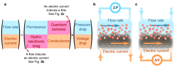
The solution adopts a matrix structure (see SI Sec. I):
| (5) |
as sketched in Fig. 2a. The diagonal elements of the transport matrix are the permeance and the conductance . We find that the off-diagonal elements are non-zero and equal, as expected from Onsager symmetry. Note that is directly proportional to the "electro-fluidic conductivity" introduced in ref. Coquinot et al. (2023a). Our model therefore not only predicts the hydro-electronic drag (a liquid flow induces an electric current, as sketched in Fig. 2b), but also its reciprocal effect (an electric current induces a liquid flow, as sketched in Fig. 2c), which has so far never been observed, and which we dub "quantum osmosis". In the following, we will call the "hydro-electronic mobility".
To provide convenient expressions of the transport coefficients, we define a dimensionless hydro-electronic coupling constant
| (6) |
quantifies the competition between liquid-electron momentum transfer () and the various sources of momentum relaxation: classical hydrodynamic friction () and electron scattering ().
Accordingly, the expression for the hydro-electronic mobility in Eq.(5), at the core of the present study, takes the form
| (7) |
It vanishes in the absence of electro-fluidic friction () and grows to infinity as 1.
The formalism also provides expression for the diagonal terms of the transport matrix: the permeance, which determines the flow rate under a pressure drop ( for )
| (8) |
where is the hydrodynamic slip length; and the conductance, which determines the electric current under a voltage drop (for )
| (9) |
where is the total electron scattering rate. These expressions highlight that the hydro-electronic coupling modifies the usual pressure-driven and volltage-driven transport phenomena. In the absence of hydro-electronic coupling () the permeance and the conductance reduce to the Poiseuille formula and the Drude formula, respectively. When , we find that both transport coefficients are enhanced. Physically, the flow-induced electric current boosts the liquid flow along the wall. Conversely, the current-induced liquid flow makes the electrons move faster inside the wall.
Overall, we have derived a new transport matrix formalism the solid-liquid interface, which bears analogy with the theoretical descriptions of osmotic effects in solution Marbach and Bocquet (2019) or thermoelectric effects in the solid state DiSalvo (1999); Shi et al. (2020). We may check explicitly that the transport matrix L is definite positive, so that our model satisfies the second law of thermodynamics. We may also invert it in order to determine the voltage induced by the liquid flow in the case where the electric circuit is open, or the hydrostatic pressure induced by the electric current if the channel is closed (see SI Sec. I).
Let us now use the transport matrix to determine the efficiency of the hydronic generator.
Efficiency and figure of merit
The mechanical power required to impose a flow rate through the hydronic generator is . The transport matrix yields the corresponding pressure drop and the induced electric current (see SI Sec. IV). The resulting voltage drop is determined by the external load resistance connected to the electric circuit: . The electric power delivered to the load resistance is then , and the hydroelectric energy conversion efficiency is defined as .
The efficiency depends on the magnitude of the load resistance, or equivalently on the current circulating through the electric circuit. At vanishing load resistance, the maximum current is . For a given value of , the efficiency can be expressed in terms of two dimensionless numbers, the normalized electric current and the figure of merit :
| (10) |
with
| (11) |
This definition of the hydro-electronic figure of merit is inspired by its thermoelectric analogue. Physically, compares the liquid-electron energy transfer rate () to the rate of energy dissipation in the system, which originates from electron scattering (), classical hydrodynamic friction (), and viscous effects in the fluid ().
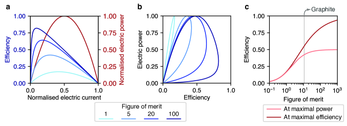
The efficiency vanishes when and approaches 1 with increasing : here, the efficiency is not limited by the Carnot efficiency as there are no temperature gradients involved. For a given , there is a value of electric current that achieves the maximum efficiency (see Fig. 3a and b), given by
| (12) |
The delivered electric power is conveniently expressed as
| (13) |
where is the permeance of the channel in the absence of flow-induced electric current. There is a value of that achieves maximum power, which is different from the one that achieves maximum efficiency. This tradeoff is highlighted by the full power-efficiency diagram displayed in Fig. 3c.
We may now qualitatively analyze the requirements for a large figure of merit , and contrast them with the case of thermoelectricity. The thermoelectric figure of merit is essentially controlled by the ratio of electrical and thermal conductivity in a given material. These two quantities tend to vary together, which makes it difficult to achieve a figure of merit exceeding unity. In the hydro-electronic case, however, there is no contradiction between maximizing the electron-liquid interaction and minimizing dissipation (essentially, surface roughness and electron-phonon coupling). It is therefore of interest to make a quantitative assessment of the efficiency achievable in a hydronic generator and of the ensuing potential for waste flow recovery.
Waste flow recovery
We first provide a simplified expression of the figure of merit by analyzing the relative importance of the dissipation mechanisms. Typical hydrodynamic friction coefficients are in the range Pa.s/m. The electron relaxation (mostly due to electron-phonon scattering at room temperature) is strongly material-dependent, but is typically in the range Pa.s/m (SI Sec. II). Thus, in most practical cases, dissipation is dominated by viscosity and interfacial friction effects and the figure of merit simplifies to
| (14) |
This expression involves two physically meaningful quantities: the ratio of the hydro-electronic and classical friction coefficients and the ratio of channel radius and slip length . The latter reflects that if the channel is large, most of the mechanical power is lost to viscous dissipation inside the fluid, rather than converted to electric power at the interface. Conversely, a sufficiently narrow channel () allows for dissipation-free plug flow. The larger , the narrower the channel needs to be to avoid viscous losses.
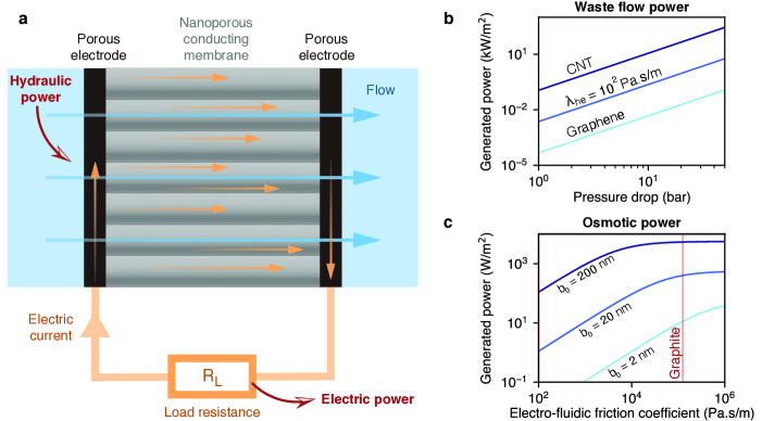
As a case study, let us analyze the performance of a hydronic generator based on a multiwall carbon nanotube (CNT) membrane Hinds et al. (2004); Holt et al. (2006), as sketched in Fig. 4a. It was shown that, if sufficiently large, these tubes exhibit a specific plasmon mode, which results in significant quantum friction for water: for a tube of radius (where ) Kavokine et al. (2022a); Secchi et al. (2016). The corresponding figure of merit is indeed significant: , allowing for a maximum efficiency . Thus, a CNT-based hydronic generator could recover more than half of the energy lost to waste flows in a membrane-based filtration process. In reverse osmosis desalination, for example, sea water is pressurized to around 60 bar at the system inlet, and the brine released at the outlet is still at a high pressure, around . Large scale desalination plants implement recovery devices for this brine flow, such as Pelton turbines and hydraulic pressure exchangers Schunke et al. (2020). While these devices work with efficiency close to unity in large plants, they are unsuitable for single-household or portable desalination systems. The energy recovery provided by a hydronic generator could thus make these small scale systems efficient enough for widespread use. Similarly, waste flows generated from waste heat Barragán and Kjelstrup (2017); Pascual et al. (2023) could be efficiently recovered through a hydronic generator at the individual scale. We note that CNTs are considered here as a model system, since their properties have been characterized in details in the literature. While CNT membranes are difficult to scale up, there exist many alternative materials that could exhibit similar properties (graphene oxides, lamellar conducting MXenes Gogotsi and Anasori (2019), etc.) and that should be considered as technological pathways to hydronic energy. As a guideline, materials with a relatively low density of high-effective-mass electrons are promising for achieving large figures of merit (SI Fig. 1). For reference, Fig. 4b shows the recovered power per unit area as a function of waste flow pressure for a CNT membrane, as well as for model membrane materials characterized by their hydro-electronic friction coefficient.
A further promising application of the hydronic generator is blue energy harvesting through pressure retarded osmosis (PRO). In PRO, the osmotic pressure difference between fresh water and sea water – separated by a semi-permeable membrane – is used to drive a water flow, which is fed into a turbine. Due to the low permeability of the membrane, a flow rate that is sufficient to spin a turbine is achieved only at the power plant scale. Replacing the turbine with a hydronic generator would make the technology viable at smaller scales: with the CNT-based model system, we estimate an achievable power density of (see SI Sec. IV), which is larger than what has so far been achieved with a turbine (). An even higher power density could be achieved with a hypothetical semi-permeable and electrically-conducting membrane, that would simultaneously express the osmotic pressure and harvest the energy from the resulting flow. Indeed, in PRO, most of the energy stored in the salinity gradient is lost to hydrodynamic friction with the membrane. A hydronic generator would instead convert this energy into electricity. With a semi-permeable membrane that exhibits the same friction characteristics as graphite, a power density exceeding could be achieved (Fig. 4b). Even with a small hydro-electronic friction (), a power density exceeding the industrial relevance threshold of is within reach Siria et al. (2017). We note that, in single nanopore systems, while ion-based osmotic power densities up to have been demonstrated Siria et al. (2013); Feng et al. (2016), this figure plummets upon scale-up due to concentration polarization effects and limitations of the electrodes Wang et al. (2022). Here, we stress that the energy conversion mechanism is ion free, hence it is expected to face fewer scale-up limitations.
Perspectives
We have established several unique characteristics of hydro-electronic drag, that set it apart from other hydroelectric energy conversion principles. At the macroscopic scale, turbines are robust and efficient converters, based on inertial effects. As inertia vanishes at smaller scales, "chemical" energy conversion takes over: the energy stored in the fluid is first converted to an ionic current, which is then transformed into an electronic current thanks to an electrochemical reaction. Hydro-electronic drag uses neither inertia nor chemistry, and thus plays the role of a seemingly impossible "nanoscale turbine".
We have developed a complete thermodynamic formalism for the hydro-electronic cross-couplings at the basis of this nanoscale turbine. A strong analogy can be established with thermoelectric cross-couplings: the induction of an electric current by a liquid flow is reminiscent of the Seebeck effect, while the induction of a liquid flow by an electric current (quantum osmosis) is analogous to the Peltier effect. But a key difference with thermoelectricity is that the relevant figure of merit is controlled by largely independent parameters, and can therefore significantly exceed unity – a peculiarity rooted in the interfacial nature of hydro-electronic effects. Thanks to this peculiarity, hydro-electronic drag is a promising principle for harvesting energy from low Reynolds number waste flows, particularly those that arise in small-scale desalination and pressure-retarded osmosis. Technologies based on hydro-electronic drag will place constraints on membrane materials that are very different from those in electrochemical technologies, as the materials’ electronic excitations will come into play. Our results suggest that there are practical consequences for the water-energy nexus of the fundamental fact that, at the nanoscale, classical fluid dynamics meet the quantum dynamics of electronic matter.
Acknowledgements
The authors thank Mathieu Lizée and Damien Toquer for fruitful discussions. The authors acknowledge support from ERC project n-AQUA, grant agreement . B.C. acknowledges support from the CFM Foundation. The Flatiron Institute is a division of the Simons Foundation.
References
- Gordon (2001) J L Gordon, “Hydraulic turbine efficiency,” Canadian Journal of Civil Engineering 28, 238–253 (2001).
- Deam et al. (2008) R. T. Deam, E. Lemma, B. Mace, and R. Collins, “On Scaling Down Turbines to Millimeter Size,” Journal of Engineering for Gas Turbines and Power 130, 052301 (2008).
- Lemma et al. (2008) E. Lemma, R. T. Deam, D. Toncich, and R. Collins, “Characterisation of a small viscous flow turbine,” Experimental Thermal and Fluid Science 33, 96–105 (2008).
- McGinnis et al. (2007) Robert L. McGinnis, Jeffrey R. McCutcheon, and Menachem Elimelech, “A novel ammonia–carbon dioxide osmotic heat engine for power generation,” Journal of Membrane Science 305, 13–19 (2007).
- Hu et al. (2010) Renchong Hu, Baratunde A. Cola, Nanda Haram, Joseph N. Barisci, Sergey Lee, Stephanie Stoughton, Gordon Wallace, Chee Too, Michael Thomas, Adrian Gestos, Marilou E. dela Cruz, John P. Ferraris, Anvar A. Zakhidov, and Ray H. Baughman, “Harvesting Waste Thermal Energy Using a Carbon-Nanotube-Based Thermo-Electrochemical Cell,” Nano Letters 10, 838–846 (2010).
- Lin et al. (2014) Shihong Lin, Ngai Yin Yip, Tzahi Y. Cath, Chinedum O. Osuji, and Menachem Elimelech, “Hybrid Pressure Retarded Osmosis–Membrane Distillation System for Power Generation from Low-Grade Heat: Thermodynamic Analysis and Energy Efficiency,” Environmental Science & Technology 48, 5306–5313 (2014).
- Siria et al. (2017) Alessandro Siria, Marie-Laure Bocquet, and Lydéric Bocquet, “New avenues for the large-scale harvesting of blue energy,” Nature Reviews Chemistry 1, 1–10 (2017).
- Barragán and Kjelstrup (2017) V. María Barragán and Signe Kjelstrup, “Thermo-osmosis in Membrane Systems: A Review,” Journal of Non-Equilibrium Thermodynamics 42, 217–236 (2017).
- Pascual et al. (2023) Marc Pascual, Nicolas Chapuis, Soufiane Abdelghani-Idrissi, Marie-Caroline Jullien, Alessandro Siria, and Lydéric Bocquet, “Waste heat recovery using thermally responsive ionic liquids through TiO2 nanopore and macroscopic membranes,” Energy & Environmental Science 16, 4539–4548 (2023).
- Xie et al. (2014) Yanbo Xie, Diederik Bos, Lennart J. de Vreede, Hans L. de Boer, Mark-Jan van der Meulen, Michel Versluis, Ad J. Sprenkels, Albert van den Berg, and Jan C. T. Eijkel, “High-efficiency ballistic electrostatic generator using microdroplets,” Nature Communications 5, 3575 (2014).
- Nie et al. (2019) Jinhui Nie, Ziming Wang, Zewei Ren, Shuyao Li, Xiangyu Chen, and Zhong Lin Wang, “Power generation from the interaction of a liquid droplet and a liquid membrane,” Nature Communications 10, 2264 (2019).
- Xu et al. (2020) Wanghuai Xu, Huanxi Zheng, Yuan Liu, Xiaofeng Zhou, Chao Zhang, Yuxin Song, Xu Deng, Michael Leung, Zhengbao Yang, Ronald X. Xu, Zhong Lin Wang, Xiao Cheng Zeng, and Zuankai Wang, “A droplet-based electricity generator with high instantaneous power density,” Nature 578, 392–396 (2020).
- Riaud et al. (2021) Antoine Riaud, Cui Wang, Jia Zhou, Wanghuai Xu, and Zuankai Wang, “Hydrodynamic constraints on the energy efficiency of droplet electricity generators,” Microsystems & Nanoengineering 7, 1–10 (2021).
- Yang et al. (2017) Peihua Yang, Kang Liu, Qian Chen, Jia Li, Jiangjiang Duan, Guobin Xue, Zisheng Xu, Wenke Xie, and Jun Zhou, “Solar-driven simultaneous steam production and electricity generation from salinity,” Energy & Environmental Science 10, 1923–1927 (2017).
- Ding et al. (2017) T. Ding, K. Liu, J. Li, G. Xue, Q. Chen, L. Huang, B. Hu, and J. Zhou, “All-Printed Porous Carbon Film for Electricity Generation from Evaporation-Driven Water Flow,” Advanced Functional Materials 27 (2017), 10.1002/adfm.201700551.
- Xue et al. (2017) Guobin Xue, Ying Xu, Tianpeng Ding, Jia Li, Jun Yin, Wenwen Fei, Yuanzhi Cao, Jin Yu, Longyan Yuan, Li Gong, Jian Chen, Shaozhi Deng, Jun Zhou, and Wanlin Guo, “Water-evaporation-induced electricity with nanostructured carbon materials,” Nature Nanotechnology 12, 317–321 (2017).
- Dao et al. (2020) Van-Duong Dao, Ngoc Hung Vu, and Ho-Suk Choi, “All day Limnobium laevigatum inspired nanogenerator self-driven via water evaporation,” Journal of Power Sources 448, 227388 (2020).
- Ghosh et al. (2003) Shankar Ghosh, A. K. Sood, and N. Kumar, “Carbon Nanotube Flow Sensors,” Science 299, 1042–1044 (2003).
- Dhiman et al. (2011) Prashant Dhiman, Fazel Yavari, Xi Mi, Hemtej Gullapalli, Yunfeng Shi, Pulickel M. Ajayan, and Nikhil Koratkar, “Harvesting Energy from Water Flow over Graphene,” Nano Letters 11, 3123–3127 (2011).
- Yin et al. (2014) Jun Yin, Xuemei Li, Jin Yu, Zhuhua Zhang, Jianxin Zhou, and Wanlin Guo, “Generating electricity by moving a droplet of ionic liquid along graphene,” Nature Nanotechnology 9, 378–383 (2014).
- Rabinowitz et al. (2020) Jake Rabinowitz, Charishma Cohen, and Kenneth L. Shepard, “An Electrically Actuated, Carbon-Nanotube-Based Biomimetic Ion Pump,” Nano Letters 20, 1148–1153 (2020).
- Chen et al. (2023) Fanfan Chen, Yunhong Zhao, Anshul Saxena, Chunxiao Zhao, Mengdi Niu, Narayana R Aluru, and Jiandong Feng, “Inducing Electric Current in Graphene Using Ionic Flow,” Nano Letters , acs.nanolett.3c00821 (2023).
- Xiong et al. (2023) Mingye Xiong, Kewei Song, and Jean-Pierre Leburton, “Ionic coulomb drag in nanofluidic semiconductor channels for energy harvest,” Nano Energy 117, 108860 (2023).
- Wang et al. (2022) Zhangxin Wang, Li Wang, and Menachem Elimelech, “Viability of Harvesting Salinity Gradient (Blue) Energy by Nanopore-Based Osmotic Power Generation,” Engineering 9, 51–60 (2022).
- Lizée et al. (2023) Mathieu Lizée, Alice Marcotte, Baptiste Coquinot, Nikita Kavokine, Karen Sobnath, Clément Barraud, Ankit Bhardwaj, Boya Radha, Antoine Niguès, Lydéric Bocquet, and Alessandro Siria, “Strong Electronic Winds Blowing under Liquid Flows on Carbon Surfaces,” Physical Review X 13, 011020 (2023).
- Coquinot et al. (2023a) Baptiste Coquinot, Lydéric Bocquet, and Nikita Kavokine, “Quantum Feedback at the Solid-Liquid Interface: Flow-Induced Electronic Current and Its Negative Contribution to Friction,” Physical Review X 13, 011019 (2023a).
- Kavokine et al. (2022a) Nikita Kavokine, Marie-Laure Bocquet, and Lydéric Bocquet, “Fluctuation-induced quantum friction in nanoscale water flows,” Nature 602, 84–90 (2022a).
- Bui et al. (2023) Anna T. Bui, Fabian L. Thiemann, Angelos Michaelides, and Stephen J. Cox, “Classical Quantum Friction at Water–Carbon Interfaces,” Nano Letters 23, 580–587 (2023).
- Yu et al. (2023) Xiaoqing Yu, Alessandro Principi, Klaas-Jan Tielrooij, Mischa Bonn, and Nikita Kavokine, “Electron cooling in graphene enhanced by plasmon–hydron resonance,” Nature Nanotechnology , 1–7 (2023).
- Coquinot et al. (2023b) Baptiste Coquinot, Maximilian Becker, Roland R. Netz, Lydéric Bocquet, and Nikita Kavokine, “Collective modes and quantum effects in two-dimensional nanofluidic channels,” Faraday Discussions , 10.1039.D3FD00115F (2023b).
- Kavokine et al. (2022b) Nikita Kavokine, Paul Robin, and Lydéric Bocquet, “Interaction confinement and electronic screening in two-dimensional nanofluidic channels,” The Journal of Chemical Physics 157, 114703 (2022b).
- Secchi et al. (2016) Eleonora Secchi, Sophie Marbach, Antoine Niguès, Derek Stein, Alessandro Siria, and Lydéric Bocquet, “Massive radius-dependent flow slippage in carbon nanotubes,” Nature 537, 210–213 (2016).
- Narozhny and Levchenko (2016) B. N. Narozhny and A. Levchenko, “Coulomb drag,” Reviews of Modern Physics 88, 025003 (2016).
- King (2023) Sarah B. King, “Quantum friction with water effectively cools graphene electrons,” Nature Nanotechnology 18, 842–843 (2023).
- Kavokine et al. (2021) Nikita Kavokine, Roland R. Netz, and Lydéric Bocquet, “Fluids at the Nanoscale: From Continuum to Subcontinuum Transport,” Annual Review of Fluid Mechanics 53, 377–410 (2021).
- Král and Shapiro (2001) Petr Král and Moshe Shapiro, “Nanotube Electron Drag in Flowing Liquids,” Physical Review Letters 86, 131–134 (2001).
- Lizée et al. (2024) Mathieu Lizée, Baptiste Coquinot, Guilhem Mariette, Alessandro Siria, and Lydéric Bocquet, “Anomalous friction of supercooled glycerol on mica,” (2024), arxiv:2403.18693 [cond-mat] .
- Marbach and Bocquet (2019) Sophie Marbach and Lydéric Bocquet, “Osmosis, from molecular insights to large-scale applications,” Chemical Society Reviews 48, 3102–3144 (2019).
- DiSalvo (1999) Francis J. DiSalvo, “Thermoelectric Cooling and Power Generation,” Science 285, 703–706 (1999).
- Shi et al. (2020) Xiao-Lei Shi, Jin Zou, and Zhi-Gang Chen, “Advanced Thermoelectric Design: From Materials and Structures to Devices,” Chemical Reviews 120, 7399–7515 (2020).
- Hinds et al. (2004) Bruce J. Hinds, Nitin Chopra, Terry Rantell, Rodney Andrews, Vasilis Gavalas, and Leonidas G. Bachas, “Aligned Multiwalled Carbon Nanotube Membranes,” Science 303, 62–65 (2004).
- Holt et al. (2006) Jason K. Holt, Hyung Gyu Park, Yinmin Wang, Michael Stadermann, Alexander B. Artyukhin, Costas P. Grigoropoulos, Aleksandr Noy, and Olgica Bakajin, “Fast Mass Transport Through Sub-2-Nanometer Carbon Nanotubes,” Science (2006), 10.1126/science.1126298.
- Schunke et al. (2020) Andrew James Schunke, German Alberto Hernandez Herrera, Lokesh Padhye, and Terri-Ann Berry, “Energy Recovery in SWRO Desalination: Current Status and New Possibilities,” Frontiers in Sustainable Cities 2 (2020), 10.3389/frsc.2020.00009.
- Gogotsi and Anasori (2019) Yury Gogotsi and Babak Anasori, “The Rise of MXenes,” ACS Nano 13, 8491–8494 (2019).
- Siria et al. (2013) Alessandro Siria, Philippe Poncharal, Anne-Laure Biance, Rémy Fulcrand, Xavier Blase, Stephen T. Purcell, and Lydéric Bocquet, “Giant osmotic energy conversion measured in a single transmembrane boron nitride nanotube,” Nature 494, 455–458 (2013).
- Feng et al. (2016) Jiandong Feng, Michael Graf, Ke Liu, Dmitry Ovchinnikov, Dumitru Dumcenco, Mohammad Heiranian, Vishal Nandigana, Narayana R. Aluru, Andras Kis, and Aleksandra Radenovic, “Single-layer MoS2 nanopores as nanopower generators,” Nature 536, 197–200 (2016).