High temperature spin selectivity in a quantum
dot qubit using reservoir spin accumulation
Abstract
Employing spins in quantum dots for fault-tolerant quantum computing in large-scale qubit arrays with on-chip control electronics requires high-fidelity qubit operation at elevated temperature. This poses a challenge for single spin initialization and readout. Existing schemes rely on Zeeman splitting or Pauli spin blockade with typical energy scales of 0.1 or 1 meV for electron-based qubits, so that sufficient fidelity is obtained only at temperatures around or below 0.1 or 1 K, respectively. Here we describe a method to achieve high temperature spin selectivity in a quantum dot using a reservoir with a spin accumulation, which deterministically sets the spin of a single electron on the dot. Since spin accumulation as large as 10 meV is achievable in silicon, spin selection with electrically adjustable error rates below is possible even in a liquid He bath at 4 K. Via the reservoir spin accumulation, induced and controlled by a nearby ferromagnet, classical information (magnetization direction) is mapped onto a spin qubit. These features provide the prospect of spin qubit operation at elevated temperatures and connect the worlds of quantum computing and spintronics.
I INTRODUCTION
The development of quantum computers based on spin in quantum dots review1 ; review2 has made tremendous advances, from the demonstration of initialization elzerman ; simmons ; taruchananomagnet2 , coherent control petta ; koppens ; kawakaminanomagnet ; taruchananomagnet2 and readout elzerman ; carroll ; west ; defranceschi of the single spin quantum state, via two-qubit operations twoqubit1 ; twoqubit2 , to architecture design architecture1 ; architecture2 and manufacturing with advanced semiconductor technology CMOSmanufacturing . For large scale arrays of multi-terminal quantum dot (QD) qubits, the control electronics should be integrated on-chip to avoid an interconnect problem architecture1 ; architecture2 . This creates another challenge yanghot ; petithot ; warburton , because balancing the heat generated by the control electronics is difficult at temperatures below 100 mK in a dilution refrigerator, which has limited cooling power. In a liquid He bath at 4.2 K the cooling power is three orders of magnitude higher. Hence, it is indispensable that qubits can operate at higher temperatures yanghot ; petithot ; warburton while at the same time maintaining error rates well below the threshold () for fault-tolerant quantum computing faulttolerant1 ; faulttolerant2 .
The traditional method elzerman ; simmons ; taruchananomagnet2 of initialization/readout of a QD spin qubit, based on Zeeman spin splitting of the dot’s energy levels in a magnetic field (Fig. 1a), yields limited fidelity and operation temperature 100 mK because the Zeeman splitting is 0.1 meV for practical values of . Therefore, only at very low selective tunneling of an electron from the lead into the lowest-energy spin state (initialization) occurs. Thermal broadening in the leads at elevated makes the higher-energy spin state accessible, thus producing initialization errors. A similar issue occurs for readout. Attention has therefore necessarily shifted to the only other available method for initialization/readout, which is based on Pauli spin blockade pauli1 ; petta ; koppens ; pauli2 in double QD qubits. This method, which has been around for more than two decades, has a larger energy scale that is set by the singlet-triplet splitting. For electron-based quantum dots, the singlet-triplet splitting is often comparable to the valley splitting, with reported values of 0.3 - 0.8 meV for Si quantum dots spinvalley1 and up to about 0.3 meV for the SiGe/Si system philips . The readout window is enhanced philips for certain multi-electron configurations in which the orbital excited state energy comes into play (an orbital excited state energy of 1 meV was measured for a 4-electron Si quantum dot orbital ). With Pauli spin blockade, qubit operation at 1 K was achieved for Si quantum dots with electrons yanghot ; petithot and holes warburton with fidelities that are approaching the fault-tolerance threshold, although some degradation for higher T up to 4 K was also observed warburton . Fidelities exceeding the fault-tolerance threshold have recently been reported noiri ; xue ; mills , but only at temperatures below 100 mK. While these are significant advances, one already operates close to the limits of the Pauli spin blockade technique. What is desirable is a method for initialization/readout that can provide a leap forward.
II RESULTS AND DISCUSSION
Principle of the approach
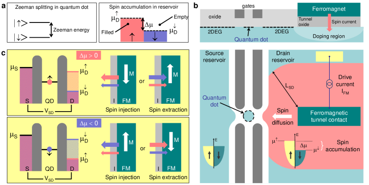
The scheme for the high temperature initialization and readout of QD spins we describe here employs a drain reservoir with a spin accumulation . The electrochemical potentials and for the spin-up and spin-down electrons describe the spin-dependent occupation of the electronic states of the reservoir (Fig. 1a). Because can be much larger than the thermal broadening, in a wide energy interval between and , the reservoir states are completely empty or full, depending on the spin. This provides a thermally robust spin selectivity. The can be created by electrical jedema1 ; tombros ; crowellnphys ; jansennmatreview ; 2tmrvanwees ; spiesserpra ; jansennonlinear ; shiraishipra ; spiesser90percent , dynamical spinpumping1 ; spinpumping2 ; spinpumping3 or thermal slachter ; lebreton spin injection from a ferromagnetic (FM) contact, or via the spin Hall effect spinhall1 ; spinhall2 ; spinhall3 . We consider spin injection by a spin-polarized current across a FM tunnel contact to the reservoir (Fig. 1b). This allows routine creation of spin accumulation, with values as large as 13 meV at 10 K (3.5 meV at 300 K) for n-type Si with Fe/MgO contacts spiesserpra ; jansennonlinear ; spiesser90percent , and 4.1 meV at 300 K in graphene 2tmrvanwees . The is proportional to the tunnel spin polarization and to and is thus electrically tunable. The sign of can be reversed by either reversing the magnetization of the contact, or the current polarity jansennonlinear (Fig. 1c). Since decays with distance from the injection contact on the scale of the spin-diffusion length , which is typically a few microns tombros ; crowellnphys ; shiraishipra , the magnetic contact is to be placed near the quantum dot (Fig. 1b). Since a large spin accumulation of holes in p-type semiconductors cannot be achieved due to the much shorter spin-relaxation time for holes hole1 ; hole2 ; hole3 ; hole4 , the method we describe here is applicable to electron-based qubits.
The spin accumulation determines the spin occupation of the QD as follows. The energy of the dot’s ground state (twofold degenerate at = 0) is positioned between and with an electrostatic gate (Fig. 1c). If , a spin-down electron can tunnel from the source to the dot, and escape into the drain because . However, as soon as a spin-up electron tunnels onto the dot, it is trapped, because there are no empty spin-up states available in the drain owing to the spin accumulation (), while the empty state the electron left behind in the reservoir is quickly filled up due to fast energy relaxation. If the charging energy of the dot is sufficiently large, Coulomb blockade prevents tunneling of a second electron onto the dot. The current is then blocked and the dot is occupied by a single electron in a quantum state (Fig. 1c). For negative spin accumulation (), the situation is similar, except that now the single electron has a quantum state. The spin accumulation thus determines the spin state of a single electron on the dot. Exchange coupling between the dot and the reservoir is not required.
Model description
In order to confirm the described behavior and quantify the characteristics, we compute the current through the quantum dot and the spin-dependent occupation probabilities and of the dot using rate equations barnas ; eques (Supplementary Note 1). Single-electron tunneling events induce transitions between the QD states (empty dot / single spin-up electron / single spin-down electron / doubly-occupied singlet state). The transition energy from the ground to the singlet state includes the Coulomb charging energy. The various tunneling rates are functions of the spin-independent tunnel coupling and of the dot to the source and drain reservoir, respectively, and of the Fermi-Dirac distribution factors. The latter depend on relative to the source () and the spin-dependent drain electrochemical potentials (, ). The source reservoir is taken to be at ground potential. The source-drain voltage shifts the drain electrochemical potentials by and shifts the quantum dot level according to ,
with the dot level energy at = 0, and the electron charge. The fraction is determined by the relative values of and (we have taken = 1/2). Spin flips in the quantum dot are included with a rate , as governed by the longitudinal spin-relaxation time , which is set to 1 ms ( is the reduced Planck’s constant). In some cases, a Zeeman splitting of the quantum dot level is included. The formalism considers quantum dot spin states that are collinear with the magnetization of the ferromagnet, which sets the quantization axis of the spin accumulation. This is sufficient for the calculation of the spin selectivity and the error rates. Transverse spin components are needed to describe the non-collinear spin states that appear during qubit spin manipulation by spin resonance. Also, orbital excited states are not included (as explained in Supplementary Note 1).
Spin selection with reservoir spin accumulation
The calculated exhibits a typical Coulomb staircase, which is modified when is non-zero (Fig. 2a). More importantly, in the presence of a spin accumulation, a spin-dependent dot occupation is produced in a wide interval, where and are either 1 or 0. A more complete picture is obtained from the stability maps produced by varying and (Fig. 2b). Without spin accumulation, the current is zero for large positive , where the dot energy level is not accessible, and in the central so-called Coulomb diamond (Fig. 2b, dotted white lines) due to Coulomb blockade. However, because = 0 and = 0, we have = everywhere. In the presence of a spin accumulation, the boundaries of the central Coulomb diamond are changed, and two regions labeled and appear in which the dot occupation is highly spin dependent (Fig. 2b). For = 2 meV, we obtain two regions with = 1 and = 0 while also = 0, implying that a single electron in a quantum state is trapped continuously on the dot. When is reversed to 2 meV, a single electron with the opposite spin state () is trapped on the dot ( = 0 and = 1). The calculations establish that the reservoir spin accumulation determines the spin quantum state of a single electron on the dot, which provides a scheme for spin qubit initialization and readout. Noteworthy is that is controlled by the magnetization of the FM contact. This means that a classical bit of information, represented by the magnetization direction, is mapped onto the quantum state of a single electron spin.
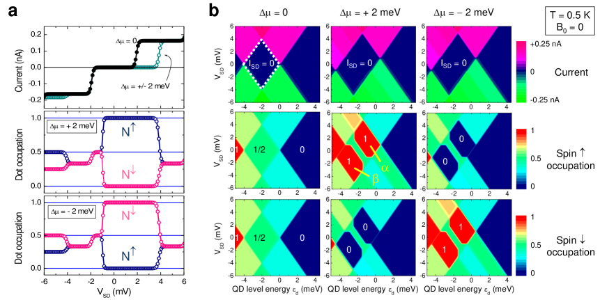
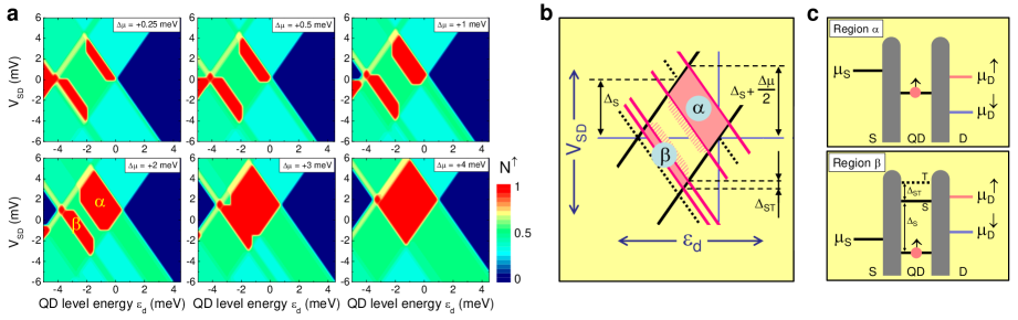
While triplet states play no role for region , they are required to properly describe region , as explained below. We therefore included triplet states in the calculations (Supplementary Note 1). The stability maps for different values of (Fig. 3a) show that the boundaries of region depend on . The upper right boundary of the central Coulomb diamond, which is defined by the dot level energy relative to the drain electrochemical potential, splits into two boundaries (solid pink lines in Fig. 3b) because . Spin selectivity then appears when the ground state lies between and , as already discussed above. For region , the origin of the spin selectivity is different (Fig. 3c). For region , the ground state lies below the reservoir electrochemical potentials, while a transition to the doubly-occupied singlet state (label S) requires an energy between and . This also produces a single electron in a quantum state (for ). A spin-down electron is not trapped in the ground state because a spin-up electron can tunnel in from the drain. From the resulting singlet state, an electron of either spin can tunnel out. If a spin-up electron tunnels out, we return to the starting configuration, and the process repeats itself until the spin-down electron tunnels out from the singlet state. This leaves behind an electron in a ground state. This is trapped if (i) the singlet state is energetically not accessible for a spin-down electron, and (ii) a spin-up electron cannot tunnel into the dot to create a triplet state (label T), which requires an additional energy given by the singlet-triplet transition energy . If , as we consider here, the lower boundary of region occurs when crosses the triplet energy and a non-zero current appears. The spin selectivity for region then results from the combination of the spin accumulation and Pauli spin blockade. Therefore, the relevant energy scale is , whereas it is for region .
High temperature spin selection
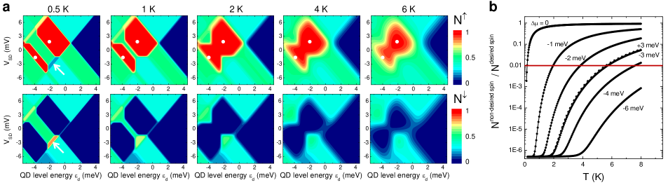
The provides a large energy scale that makes the spin selectivity robust against temperature. Region with 1 and 0 persists even at 6 K for a of 3 meV (Fig. 4a). These results were obtained with a 70 eV Zeeman splitting that favours the spin-down state, opposite to the spin accumulation. But because 70 eV, the spin accumulation defines the quantum dot spin. For region , the decays more rapidly with increasing because the relevant energy scale is , which was set to 0.5 meV. The decay of is accompanied by a finite current (of spin-up electrons via the triplet states), making region unsuitable for qubit operation at 4 K. The boundary of region for is determined by the relative position of and the singlet state, and thus by , so that for region remains 0 even at 6 K. For a more quantitative analysis, we extract the error rates from region . The error rate is defined here as the probability for finding the spin state opposite to what was desired, i.e., the error rate is for 0 and for 0. Without spin accumulation, the error rate rises quickly and surpasses the fault-tolerance threshold for 100 mK (Fig. 4b). With a spin accumulation, the error rate remains much smaller at higher . At 4.2 K, a of about 2 or 3 meV yields an error rate of 10-2 or 10-3, which is below the fault-tolerance threshold (red line). For larger spin accumulation, higher and/or smaller error rates are possible. The latter reduces the qubit array size required for computation faulttolerant1 ; faulttolerant2 .
Implementation in spin qubits
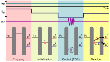
We describe a basic sequence for the initialization, control and readout of a quantum dot qubit with a reservoir spin accumulation (Fig. 5). In the simplest scheme, the magnitude and sign of the spin accumulation are kept constant throughout the entire sequence. After emptying the dot, and are adjusted so as to reach region in the stability diagram and thereby initialize a single electron with a well-defined spin on the dot. The selected spin state is determined by the sign of . A large operation window (region ) exists for and , making the system insensitive to errors produced by potential variations. In the next step, the quantum dot level is moved down so as to obtain a deep Coulomb blockade for spin manipulation by established spin resonance methods koppens ; kawakaminanomagnet ; taruchananomagnet2 . Care has to be taken that during this stage the qubit spin is not disturbed by the spin accumulation in the drain reservoir (see the Supplementary Discussion). In the final step, and are adjusted to their readout values. The spin accumulation enables readout because only one type of electron can tunnel out into the drain (spin down for the case of depicted in Fig. 5). The tunneling event can be detected via established charge sensing techniques elzerman ; carroll ; west ; defranceschi .
The large spin accumulation offers high spin selectivity for initialization and readout. For the overall readout fidelity, other factors also come into play, including errors that might occur in the charge sensing of the readout transition. Such errors depend on the charge sensing method and on other design details, which are beyond the scope of this work. Since is adjustable electrically (via the current through the magnetic contact to the drain), the spin selectivity can be tuned to levels for which the overall fidelity is limited only by the spin control process. Variations of the operation sequence presented in Fig. 5 are possible. For instance, the spin that is selected for initialization and readout can be changed by reversing the magnetization of the ferromagnetic contact to the drain. However, local magnetization control for each reservoir contact requires additional elements and increases the complexity and footprint of the qubit design. One might also consider active control of , for instance switching it off during the spin resonance manipulation. This needs to be done in a way that does not disturb the spin qubit (see the Supplementary Discussion for more information). It is emphasized that reversal of the spin accumulation does not constitute coherent spin control because the originally trapped electron tunnels out and is replaced by a different electron with opposite spin. It has been proposed that coherent manipulation of a qubit spin by scattering off ”flying” spins in the reservoir is possible if an exchange coupling exists between the qubit and the reservoir spins datta .
Surely, the use of a drain reservoir with a ferromagnet to create the spin accumulation introduces additional complexity, increases the size of the spin qubit, affects the scalability, and may also modify the noise during qubit operation. At the same time, the described method enables high spin selectivity, enhanced robustness at higher temperature, with a wide operation window for and . Also, the approach is conceptually simple as it uses one quantum dot with a single electron, instead of the multi-electron double-dot devices used for Pauli spin blockade yanghot ; petithot ; warburton ; pauli1 ; petta ; koppens ; pauli2 ; philips . In future work, it is of importance to investigate the required modifications to the design of the qubit array and assess whether the envisioned benefits of the described method outweigh the potential drawbacks. Some initial considerations are given in Supplementary Note 4 and the Supplementary Discussion, which also describe aspects related to the practical implementation. This includes the feasibility to induce a sufficiently large spin accumulation in the 2DEG reservoir, the applicability to different qubit material systems (not only quantum dots in Si/SiO2 2DEG’s but also SiGe/Si with a buried 2DEG, or dopant-based spin qubits), the expected dimensions of a reservoir with a ferromagnetic contact, and the drive current ( 3 nA) and power ( 20 pW) required to achieve the desired . We note that nanomagnets are already widely used yanghot ; taruchananomagnet2 ; kawakaminanomagnet ; philips ; taruchananomagnet1 in spin qubits to produce an inhomogeneous magnetic field for electrically driven spin resonance (EDSR). It is of interest to examine whether the ferromagnetic tunnel contact to the drain reservoir can have a dual function (create spin accumulation and assist in producing the magnetic field gradients required for EDSR).
In summary, we have described a scheme for high temperature initialization and readout of a spin qubit. It is based on a reservoir with a spin accumulation, which controls the spin state of a single electron on a quantum dot. The spin accumulation is induced electrically by spin injection from a nearby ferromagnetic tunnel contact. The method enables operation at elevated , even above 4.2 K, with error rates below . The error rates are electrically adjustable and the operation window for and is wide, making the approach insensitive to potential variations. Via the spin accumulation, a classical bit of information (magnetization direction) is mapped onto the quantum spin state of a single electron. This connects spin qubits and quantum computing to spintronics.
III Data availability
The authors declare that the data supporting the findings of this study are available within the paper and its Supplementary Information files.
IV Code availability
All the codes used in this work are available upon request to the authors.
V Acknowledgement
The authors thank A. Spiesser for initiating investigations into the use of spin current for spin-based quantum computing, which stimulated the authors to explore other ways to use spintronic phenomena in quantum dot qubits. We also thank S. Kawabata for useful discussion.
VI Author contributions
RJ designed the concept, performed the calculations and analysis of the results, and wrote the draft and the final manuscript. SY reviewed and gave input on the manuscript and provided overall supervision.
VII Competing interests
The authors declare no competing interests.
VIII References
References
- (1) D. P. DiVincenzo and D. Loss, Quantum computers and quantum coherence, J. Magn. Magn. Mater. 200, 202-218 (1999).
- (2) G. Burkard, Th. D. Ladd, A. Pan, J. M. Nichol, J. R. Petta, Semiconductor spin qubits, Rev. Mod. Phys. 95, 025003 (2023).
- (3) J. M. Elzerman, R. Hanson, L. H. Willems van Beveren, B. Witkamp, L. M. K. Vandersypen, and L. P. Kouwenhoven, Single-shot read-out of an individual electron spin in a quantum dot, Nature 430, 431-435 (2004).
- (4) C. B. Simmons et al., Tunable spin loading and T1 of a silicon spin qubit measured by single-shot readout, Phys. Rev. Lett. 106, 156804 (2011).
- (5) K. Takeda et al., A fault-tolerant addressable spin qubit in a natural silicon quantum dot, Sci. Adv. 2, e1600694 (2016).
- (6) J. R. Petta et al., Coherent manipulation of coupled electron spins in semiconductor quantum dots, Science 309, 2180-2184 (2005).
- (7) F. H. L. Koppens et al., Driven coherent oscillations of a single electron spin in a quantum dot, Nature 442, 766-771 (2006).
- (8) E. Kawakami et al., Electrical control of a long-lived spin qubit in a Si/SiGe quantum dot, Nat. Nanotechnol. 9, 666-670 (2014).
- (9) P. Harvey-Collard et al., High-fidelity single-shot readout for a spin qubit via an enhanced latching mechanism, Phys. Rev. X 8, 021046 (2018).
- (10) A. West et al., Gate-based single-shot readout of spins in silicon, Nat. Nanotechnol. 14, 437-441 (2019).
- (11) M. Urdampilleta et al., Gate-based high fidelity spin readout in a CMOS device, Nat. Nanotechnol. 14, 737-741 (2019).
- (12) M. Veldhorst et al., A two-qubit logic gate in silicon. Nature 526, 410-414 (2015).
- (13) D. M. Zajac et al., Resonantly driven CNOT gate for electron spins, Science 359, 439-442 (2018).
- (14) M. Veldhorst, H. G. J. Eenink, C. H. Yang, and A. S. Dzurak, Silicon CMOS architecture for a spin-based quantum computer, Nat. Commun. 8, 1766 (2017).
- (15) R. Li et al., A crossbar network for silicon quantum dot qubits, Sci. Adv. 4, eaar3960 (2018).
- (16) A. M. J. Zwerver et al., Qubits made by advanced semiconductor manufacturing, Nat. Electron. 5, 184-190 (2022).
- (17) C. H. Yang et al., Operation of a silicon quantum processor unit cell above one kelvin, Nature 580, 350-354 (2020).
- (18) L. Petit et al., Universal quantum logic in hot silicon qubits, Nature 580, 355-359 (2020).
- (19) L. C. Camenzind, S. Geyer, A. Fuhrer, R. J. Warburton, D. M. Zumbühl, and A. V. Kuhlmann, A hole spin qubit in a fin field-effect transistor above 4 kelvin, Nat. Electron. 5, 178-183 (2022).
- (20) A. Fowler, M. Marlantoni, J. M. Martinis, A. N. Cleland, Surface codes: towards practical large-scale quantum computation. Phys. Rev. A 86, 032324 (2012).
- (21) E. T. Campbell, B. M. Terhal, and C. Vuillot, Roads towards fault-tolerant universal quantum computation, Nature 549, 172-179 (2017).
- (22) K. Ono, D. Austing, Y. Tokura, and S. Tarucha, Current rectification by Pauli exclusion in a weakly coupled double quantum dot system, Science 297, 1313-1317 (2002).
- (23) C. Barthel, D. J. Reilly, C. M. Marcus, M. P. Hanson, A. C. Gossard, Rapid single-shot measurement of a singlet-triplet qubit, Phys. Rev. Lett. 103, 160503 (2009).
- (24) C. H. Yang et al., Spin-valley lifetimes in a silicon quantum dot with tunable valley splitting, Nat. Commun. 4, 2069 (2013).
- (25) S. G. J. Philips et al., Universal control of a six-qubit quantum processor in silicon, Nature 609, 919-924 (2022).
- (26) C. H. Yang, W. H. Lim, N. S. Lai, A. Rossi, A. Morello, and A. S. Dzurak, Orbital and valley state spectra of a few-electron silicon quantum dot, Phys. Rev. B 86, 115319 (2012).
- (27) A. Noiri et al., Fast universal quantum gate above the fault-tolerance threshold in silicon, Nature 601, 338-342 (2022).
- (28) X. Xue et al., Quantum logic with spin qubits crossing the surface code threshold, Nature 601, 343-347 (2022).
- (29) A. R. Mills et al., Two-qubit silicon quantum processor with operation fidelity exceeding 99%, Sci. Adv. 8, eabn5130 (2022).
- (30) F. J. Jedema, A. T. Filip, and B. J. van Wees, Electrical spin injection and accumulation at room temperature in an all-metal mesoscopic spin valve, Nature 410, 345-348 (2001).
- (31) N. Tombros, C. Jozsa, M. Popinciuc, H. T. Jonkman, and B. J. van Wees, Electronic spin transport and spin precession in single graphene layers at room temperature, Nature 448, 571-574 (2007).
- (32) X. Lou et al., Electrical detection of spin transport in lateral ferromagnet-semiconductor devices, Nat. Phys. 3, 197-202 (2007).
- (33) R. Jansen, Silicon spintronics, Nature Mater. 11, 400-408 (2012).
- (34) M. Gurram, S. Omar, and B.J. van Wees, Bias induced up to 100% spin-injection and detection polarizations in ferromagnet/bilayer-hBN/graphene/hBN heterostructures, Nat. Commun. 8, 248 (2017).
- (35) A. Spiesser et al., Giant spin accumulation in silicon nonlocal spin-transport devices, Phys. Rev. Appl. 8, 064023 (2017).
- (36) R. Jansen et al., Nonlinear electrical spin conversion in a biased ferromagnetic tunnel contact, Phys. Rev. Applied 10, 064050 (2018).
- (37) T. Sasaki et al., Spin transport in nondegenerate Si with a spin MOSFET structure at room temperature, Phys. Rev. Applied 2, 034005 (2014); and the corresponding Erratum: Phys. Rev. Applied 9, 039901(E) (2018).
- (38) A. Spiesser, H. Saito, S. Yuasa, and R. Jansen, Tunnel spin polarization of Fe/MgO/Si contacts reaching 90% with increasing MgO thickness, Phys. Rev. B 99, 224427 (2019).
- (39) Y. Tserkovnyak, A. Brataas, and G. E. W. Bauer, Enhanced Gilbert damping in thin ferromagnetic films, Phys. Rev. Lett. 88, 117601 (2002).
- (40) R. Urban, G. Woltersdorf, and B. Heinrich, Gilbert damping in single and multilayer ultrathin films: role of interfaces in nonlocal spin dynamics, Phys. Rev. Lett. 87, 217204 (2001).
- (41) K. Ando, Dynamical generation of spin currents, Semicond. Sci. Technol. 29, 043002 (2014).
- (42) A. Slachter, F. L. Bakker, J. P. Adam, and B. J. van Wees, Thermally driven spin injection from a ferromagnet into a non-magnetic metal, Nat. Phys. 6, 879-882 (2010).
- (43) J. C. Le Breton, S. Sharma, H. Saito, S. Yuasa, and R. Jansen, Thermal spin current from a ferromagnet to silicon by Seebeck spin tunnelling, Nature 475, 82-85 (2011).
- (44) Y. K. Kato, R. C. Myers, A. C. Gossard, D. D. Awschalom, Observation of the spin Hall effect in semiconductors, Science 306, 1910-1913 (2004).
- (45) S. O. Valenzuela and M. Tinkham, Direct electronic measurement of the spin Hall effect, Nature 442, 176-179 (2006).
- (46) L. Liu, T. Moriyama, D. C. Ralph, R. A. Buhrman, Spin-torque ferromagnetic resonance induced by the spin Hall effect, Phys. Rev. Lett. 106, 036601 (2011).
- (47) D. J. Hilton and C. L. Tang, Optical orientation and femtosecond relaxation of spin-polarized holes in GaAs, Phys. Rev. Lett. 89, 146601 (2002).
- (48) E. J. Loren, J. Rioux, C. Lange, J. E. Sipe, H. M. van Driel, and A. L. Smirl, Hole spin relaxation and intervalley electron scattering in germanium, Phys. Rev. B 84, 214307 (2011).
- (49) F. Pezzoli et al., Optical spin injection and spin lifetime in Ge heterostructures, Phys. Rev. Lett. 108, 156603 (2012).
- (50) M. Kawano, K. Santo, M. Ikawa, S. Yamada, T. Kanashima, and K. Hamaya, Spin transport in p-Ge through a vertically stacked Ge/Fe3Si junction, Appl. Phys. Lett. 109, 022406 (2016).
- (51) W. Rudziński and J. Barnaś, Tunnel magnetoresistance in ferromagnetic junctions: Tunneling through a single discrete level, Phys. Rev. B 64, 085318 (2001).
- (52) F. M. Souza, J. C. Egues, and A. P. Jauho, Quantum dot as a spin-current diode: A master-equation approach, Phys. Rev. B 75, 165303 (2007).
- (53) B. Sutton and S. Datta, Manipulating quantum information with spin torque, Sci. Rep. 5, 17912 (2015).
- (54) M. Pioro-Ladrière et al., Electrically driven single-electron spin resonance in a slanting Zeeman field, Nat. Phys. 4, 776-779 (2008).