Development and property study of the extremely thin 12 -type straw tubes with 5-mm diameter for a Straw Tracker System of COMET
Abstract
The COMET experiment focuses on searching for the direct conversion of a muon into an electron with aluminum nuclei, without emitting a neutrino (so called conversion). This conversion violates charged lepton flavor conservation law, a fundamental principle in the Standard Model. The COMET experiment requirement is to achieve the muon-to-electron conversation sensitivity better than . The Straw Tracker System (STS) based on straw tubes could provide the necessary spatial resolution of 100 m and the electron momentum resolution better than 100 MeV/c
The COMET phase-II will operate with 56 kW 8 GeV proton beam increasing from 3.2 kW 8GeV proton beam proposed for COMET phase-I. The 10-mm straws system was developed for COMET-phase-I and wouldn’t perform with full efficiency with 20 times increased intensity. New STT design based on 5-mm 12-m thick straws could satisfy the requirement of increased intensity. This detector should also operate in vacuum with 1 bar internal pressure. The mechanical properties of these straws such as sagging, elongation, dependence of the diameter on over-pressure, etc are discussed in this article.
1 Introduction
The COMET (COherent Muon to Electron Transition) experiment [1] is aiming to search for neutrinoless muon-to-electron conversion . This process lies beyond of Standard Model (SM) [2, 3, 4, 5]. The straw tracker system (STS) is an essential part of the COMET experiment. The main advantage of straw chambers is reduced multiply scattering due to very low material with low density on propagation path of the charged particle which allows to increase the energy resolution for this particle holding the momentum resolution on 200 MeV/c and better. Another advantage is improved spacial resolution better then 150 m. These facts allow to achieve. This fact allows to achieve a single-event sensitivity below .
Historically, the straw tube system for first time was proposed as a tracking system for Superconducting Super Collider (SSC, [6, 7]) at 1989. And the trackers based on it was introduced for COMPASS experiment [8] and were widely in use at experiments such as PANDA [9], ATLAS[10], etc. The straw for these experiments were done by S-cladding technology when thin (36 m) a mylar film with Al or other metal layer deposit on it is winded around axis with steps in between thus creating the tubing. For instance, the straws for Straw-tube Tracker, for Mu2e experiment [11] were created with such technology.
The other type, C-type cladding technology, of the straw production was introduced for NA62 Low Mass Straw Tracker [12] when the 10-mm tube shape was formed from flat mylar film with 36 m in thickness and a seam was welded with ultrasonic welder thus creating the tubing. Straws with such technology will be used for COMET Straw Tracker [13] as well. The straws for COMET Phase-I are 10 mm in diameter and mylar thickness is 20 m.
But COMET phase-II proposed to operate with upgraded from 3.2 kW for COMET phase-I to 56 kW 8 GeV proton beam [14]. It leads to increasing the muon beam from for COMET Phase-I to for COMET Phase-II. This new conditions lead itself to improve the COMET STS to fit the requirements on spacial and momentum resolution stay the same as discussed above. The new design of the STS was proposed ([15]) based on 5-mm diameter straw tubes created using thinner - 12 - mylar in an aim to leave the total thickness of the straw system unchanged.
2 The 5-mm 12hick straw tube design production station
Explain ”C-type”!
It is the first time when the C-type 5-mm 12- straw tube was produced using the ultrasonic welding technique, so, before creating the whole system with proposed design, it is necessary to first of all create the straws according to required parameters and test their mechanical properties.
2.1 Design 5-mm diameter straw tubes design
The main component of the straw tracker for Phase II will be a straw tube with 5 mm diameter [1, 16] and 12- thin-walled mylar tube the inner side of which is covered with a 70 nm layer of aluminum (cathode). A 20- or 25- diameter of gold-plated tungsten wire, the size of which has not yet been determined (anode) could be positioned at its center with high voltage applied on it. The space between them is filled with mixture working gas under the excess pressure. Internal detector pressure should be 1 bar. All tracker system locate in superconductive magnet with 1 Tesla and operates in a vacuum.
2.2 Ultrasonic welding production station
The C-type straw tube production station was built from scratch focusing on 5-mm diameter 12 straw production
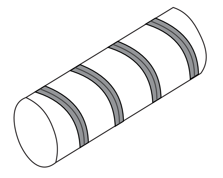
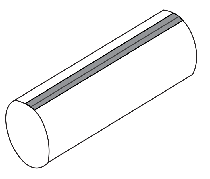
Two methods can be used for making thin-wall straw tubes, which means less material budget on the tracking detector. These are the so-called “doubly wound like helix” ((Fig. 1a)) and “direct adhesion C shape straw” without glue (Fig. 1b). Both the methods has their advantages and disadvantages to avoid weaknesses of double- winding straw for using then in vacuum. A new method ultrasonic welding technologies was developed at CERN and adapted by JINR for producing vacuum compatible C shape straws [17, 18, 19].
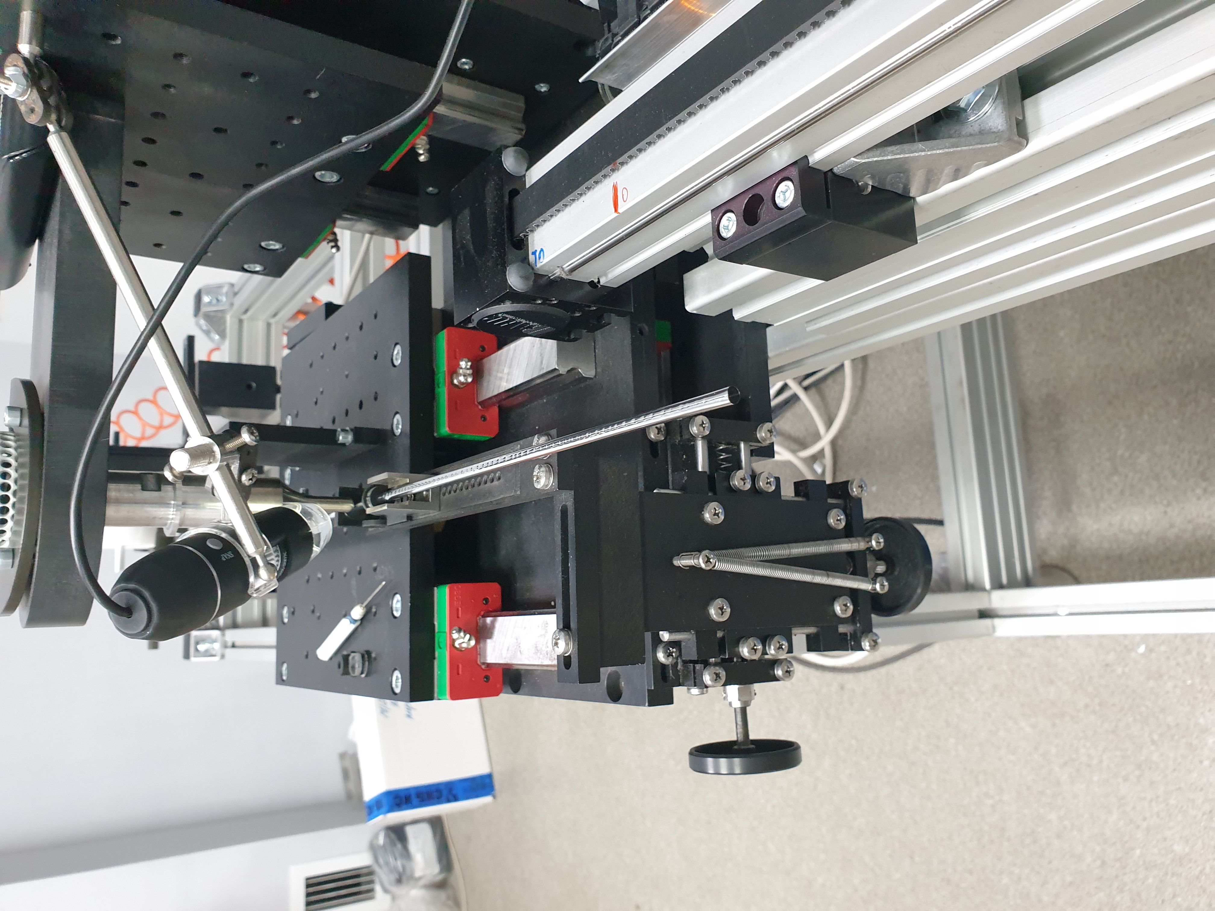
To create 5-mm diameter 12 straws, specific welding station was designed and built from scratch using ultrasonic generator with 44 kHz frequency and 25 amplitude (Fig. 2).
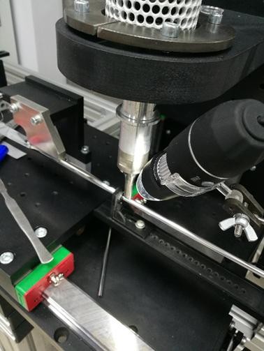
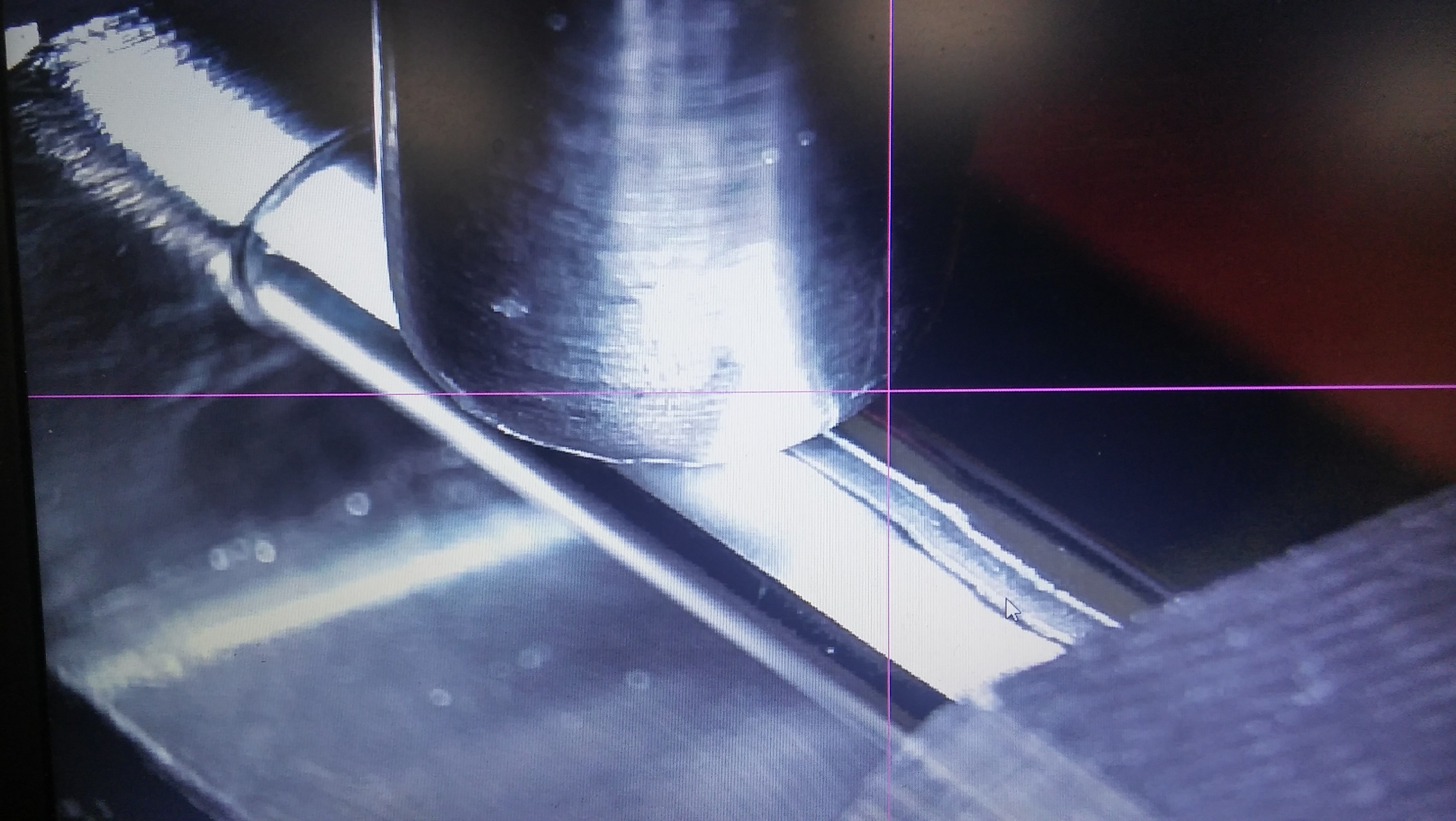
During this process, Mylar tape with single aluminum coating (cathode) is formed to the cylinder shape and overlapping edges attached by ultrasonic welding to each other in a straight line with no glue using (so-called “straight adhesion”) .
This method allows to make strong C shape straw that can keep their parameters even after installing in a stretched position and over pressurizing.
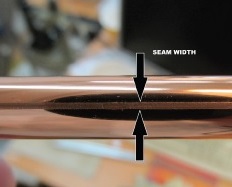
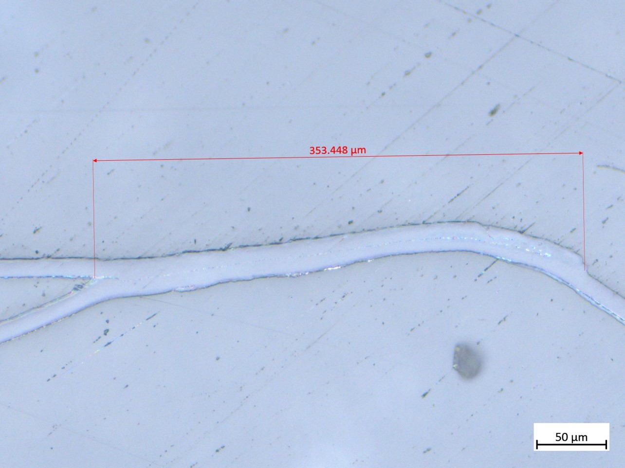
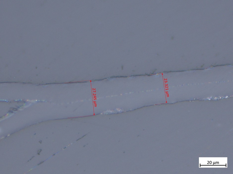
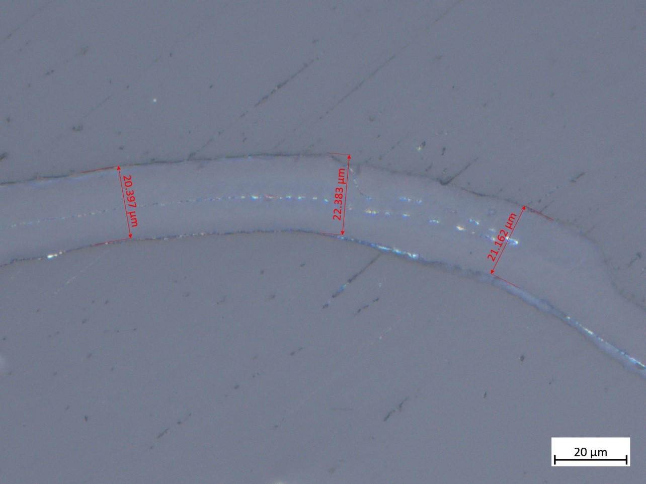
For a good operating performance therefore a homogeneous electric field can be easily achieved. It is necessary to monitor the seam size during straw production and hold it inside of the requested area since especially the seam area is responsible for major gas leakage if it takes a place - the smaller size of the seam will increase the gas leakage while larger seam will affect to the straw tube shape (Fig. 3). The reason for this gas leakage through the seam is a destruction of the metallized inner layer of the tubes during production. The typical width of the seam for 5-mm 12- straw is about 350 (Fig. 3a) and the seam thickness is around 22 (Fig. 3b, 3c).
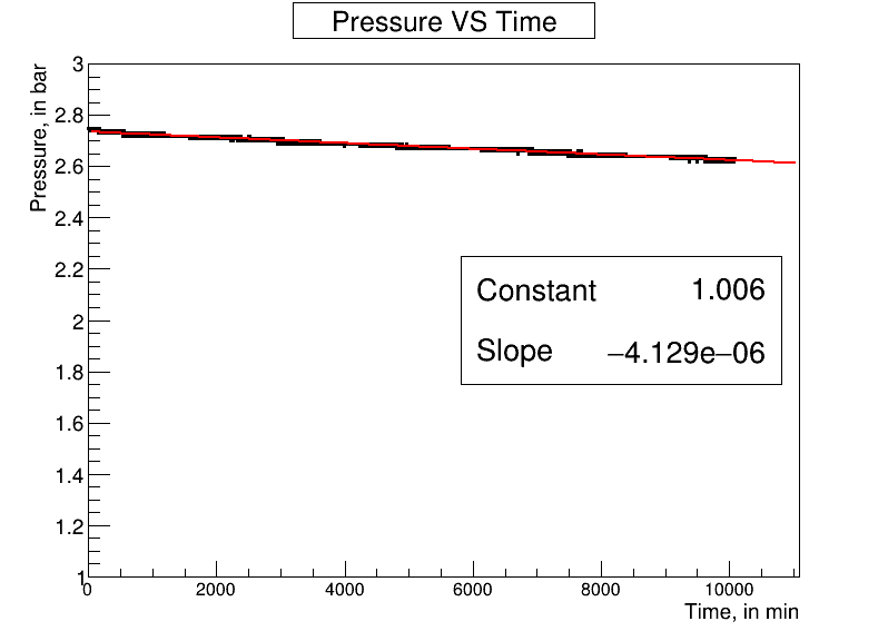
We did the preliminary test (initial pressure) of the gas leakage for these 0.6-m-long straw. To perform it, we just continuously monitor the internal pressure of the straw for a week by 1 minute interval (Fig. 4) and using the data by exponential fitting this distribution, we could estimate the speed of the pressure dropping of 6 mBar/day thus then calculate the leakage speed using the Boyle–Mariotte law. Was found that leakage speed is less than cm3/min (!should be be checked!). More careful and full-scale study of leakage we done is a subject for other publication and is in a schedule.
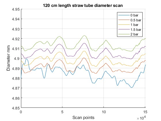
The created straw was tested for the diameter variations along to the straw to prove the production quality. The variation of the straw diameter for different internal over-pressure in the longitudinal direction is presented in Figure 5. It can be seen that this variation is very Small, inside of the 10.
3 5-mm with 12-thick wall straw tubes mechanical properties study
About 100 5-mm 12 -thick straw tubes were produced to check production stability. As a next step, the mechanical properties should be study for this type of the straw. We provided almost full set of the mechanical properties study: straw tube elongation VS load; straw tube elongation caused by internal over-pressure, straw tube diameter dependence on load and on internal over-pressure, straw tube bending since over-pressure in a vertical position and sagging caused by gravitation once straw placed horizontal. For instance, a very nice measurements for C-type 9.8-mm straw and 18-mm straw with wall thickness of 36 and 54 done in article [20].
3.1 Setup to provide the measurements
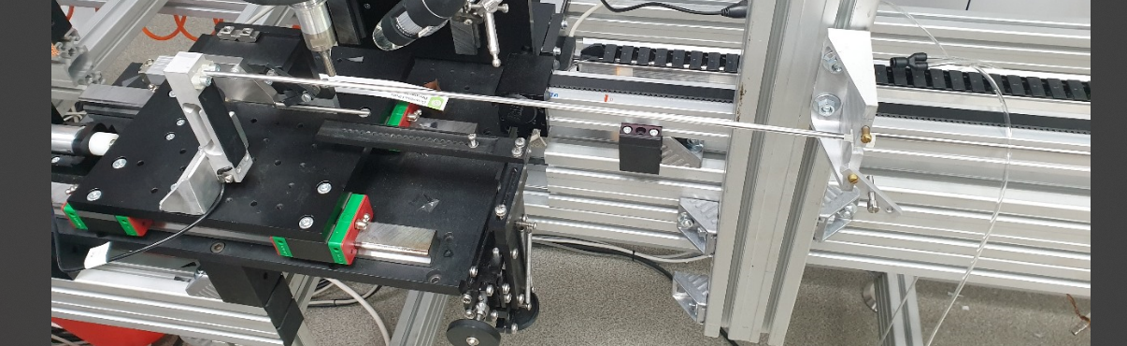
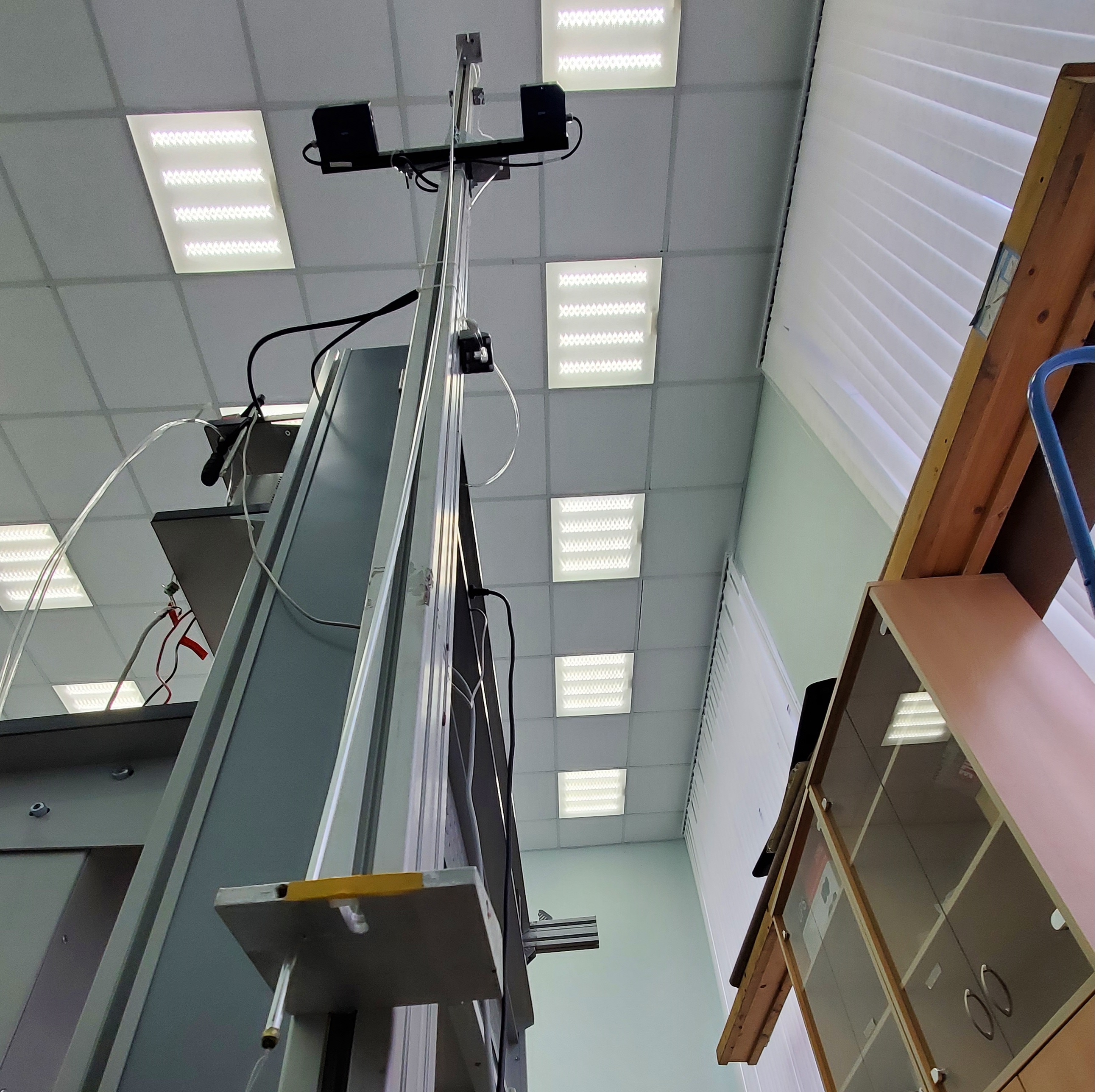
Special setup was built to provide the mechanical properties study using standard T-slot profiles. Part of it done using the setup and it was equipped with a 1-X translation stage and tension gauge on one end of the straw tube and the other end was just fixed (Fig. 6a). And rest of the measurements are done on another setup - we create from a scratch more universal setup to provide more wide tests of the straw tubes (Fig. 6b). This new setup allows us to study the tube mechanical properties with length up-to 4.5 m, can be set on different angles to azimuth from 0 to 90 degree, etc.
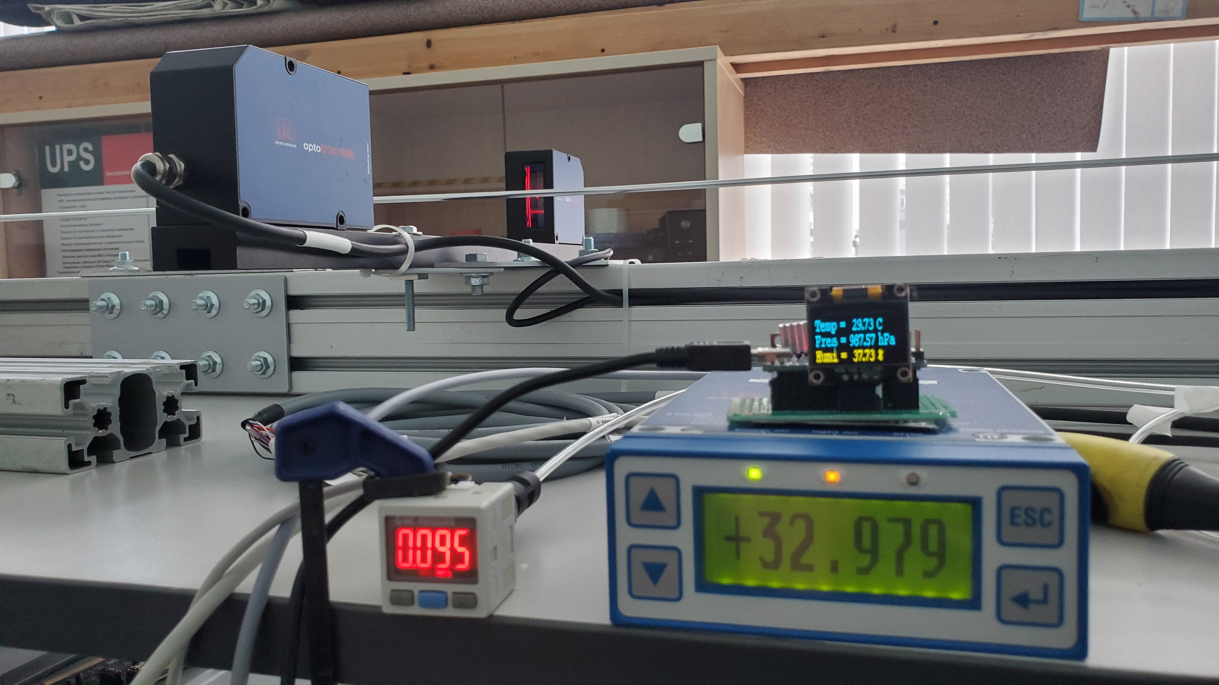
To measure the straw diameter variation, sagging and bending, a Micro-Epsilon ”optoCONTROL 2600” laser micrometer was used [21]. The sensor measurement range is based on the width of laser beam and corresponds to 40 mm with an accuracy of 1 µm (Fig. 7). This laser micrometer is able to operate in four modes and we only used two of it: ”Mode 1” - to measure the position of the edge of ”light-dark” in absolute value (Mode 1) and ”Mode 2” - to measure difference of two edges relative values. First mode allows to measure the straw tube displacement from the initial position and second mode allows to monitor the straw tube diameter during the measurements. This device is installed in the middle of the straw being measured.
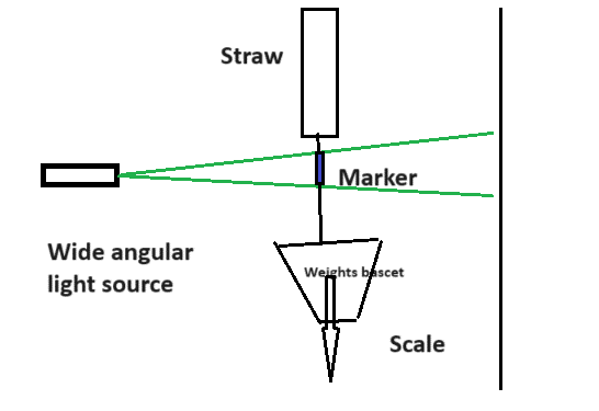
The elongation measurements provided on setup done using follow technique. The narrow laser beam spread into the the wide angle using de-focusing lens. On the end of the straw a small paper strip marker is placed. The laser is placed at the same distance to both paper marker and the screen with a ruler. The light beam was shadowed by marker and we can monitor the variation of the straw length on the screen using ruler (Fig. 8).
3.2 Straw tube elongation study as function of the external load
The straw tube elongation tests under various conditions using load were done for these tubes for 0.5, 1.0 and 1.34 meter long tubes.
The elongation test for tubes with 0.5 and 1.0 meter long tubes was done on setup (Fig. 6a) when one end of the straw tube was fixed on the tension gauge and the other end was just constantly fixed. The tension gauge was installed on the 1-X translation stage. The gauge was connected to the computer for a remote data acquisition and control. Measurements with these tubes were done with no over-pressure delivered to tubes.
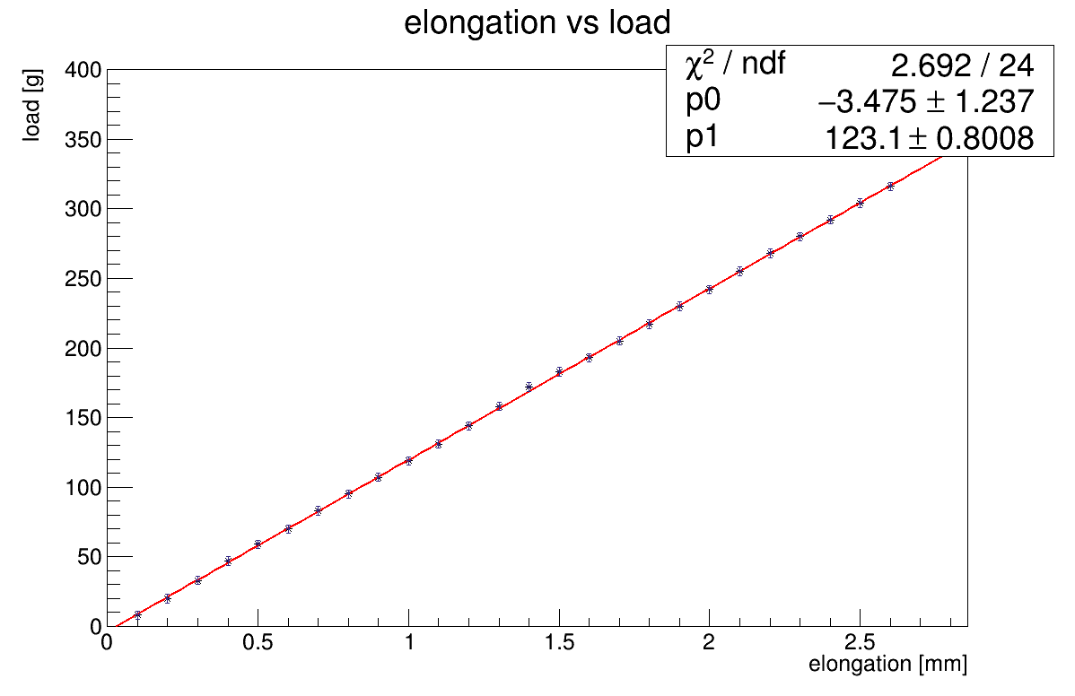
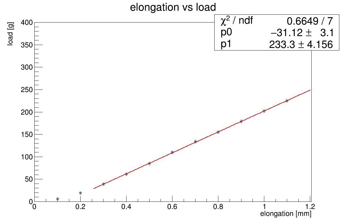
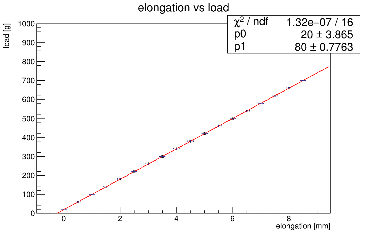
Figure 9 represents the results of these measurements. The graphs were fitted with linear function to prove that the elongation was within the elastic area according to Hooke’s law. The stiffness values were found to be equal to 233 g/mm for 0.5-m-long tube and to 123 g/mm for 1.0-m-long tube.
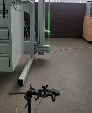
The elongation test for the 1.34 meter long straw tube was done on setup (Fig. 6b). In this case, the real weight was used to stress the tube and the tube was hung vertically strong. The marker was stuck on the end of the straw tube where the weight basket was installed. The wide spread light source used to illuminate the marker and the position of the marker shadow was monitored on screen with a scale on it located behind the straw tube (Fig. 8). The straw was placed halfway from light source to screen with scale. The values of the positions were read out by a camera installed in front of the screen.
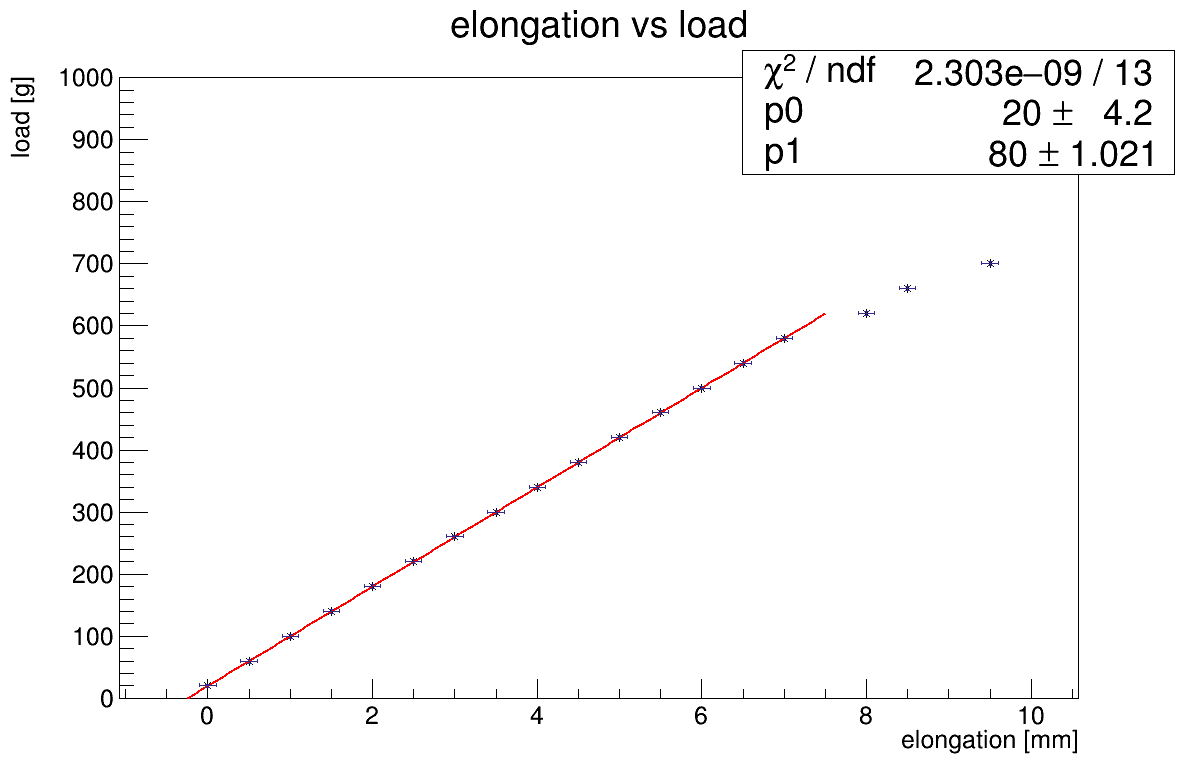
The 0.5 and 1.0 bar over-pressure were delivered into the tube to find the difference in stiffness by internal pressure. The resulting graph for the 0.5 bar over-pressure case is shown in Figure 10a and for the 1.0 bar - in Figure 10b. Again, both graphs were fitting with linear function to find the elastic area according to Hooke’s law. The stiffness values were found to be equal to 80 g/mm for 0.5 bar over-pressure and the same 80 g/mm for 1.0 bar over-pressure. So, no changes are observed with changes of the internal over-pressure of the tube, and it is expected due to negligible changes in the value of the straw tube cross-section area. One can see that in case of 1.0 bar over-pressure the elastic area is limited with 500 gram load in comparison to 0.5 bar over-pressure case which still is inside of elastic area up-to 700 gram load.
The relationship between tensile or compressive stress (force per unit area) and axial strain (proportional deformation) in the linear elastic region of a material:
The stiffness is inversely proportional to the straw tube length in other same conditions according to well known equation (1):
| (1) |
here: k - is the stiffness, - Young’s modulus for mylar, L - length of straw, - cross-sectional area of the straw tube perpendicular to the load. Please note that the dependence of the straw cross-section value by the load was negligible and we did not take it into the account.
In case of straw tubes, the relation of the thickness of the mylar (T = 12 ) for of the straw tube to it diameter (D = 5 mm) is small, , so the stiffness could be approximated as:
| (2) |
here .
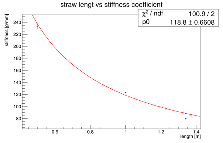
Figure 11 represents the stiffness dependence by the tube length. Red line is predicted using equation (1), blue dots are data found for 0.5, 1.0 and 1.35-m-long straw tubes. We got the value for about 119 gramm. According to this value, the Young’s modulus for the Mylar tape was found to be about 6.2 GPa and this result is very close/consistent to the 5.24 GPa () [22].
3.3 Straw tube elongation by internal pressure
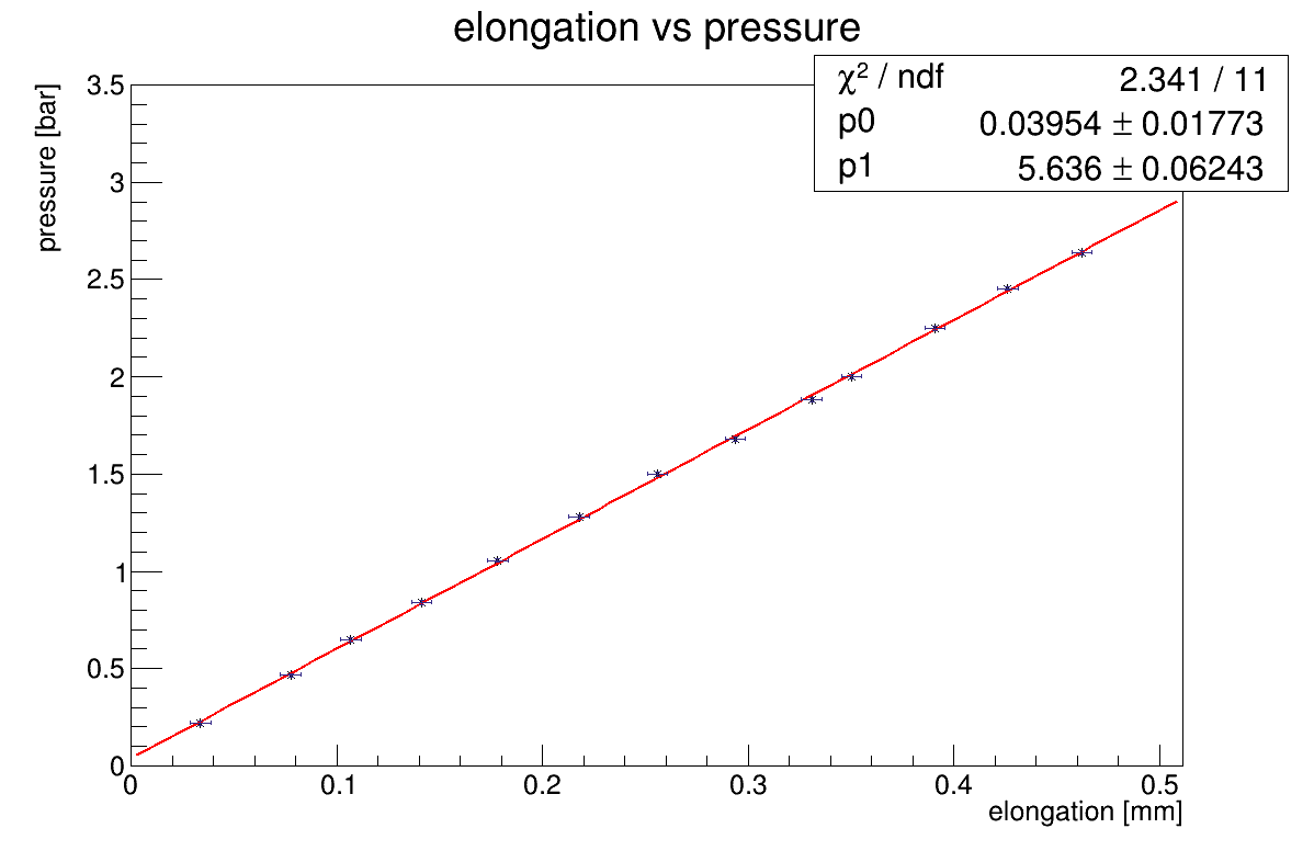
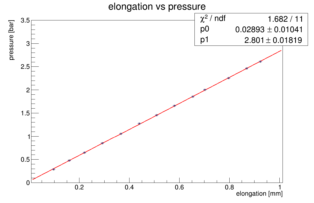
In contrast to the elongation caused by external load attached to the tube ends, it is also important to know how the elongation acts when the over-pressure is delivered into the tube. So, we measured the elongation as a function of the straw tube internal over-pressure for 0.5 and 1.0-m-long tubes and results are represented at Figure 12.
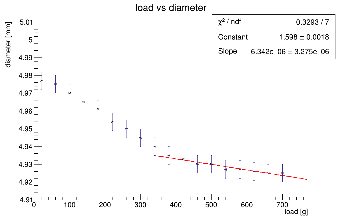
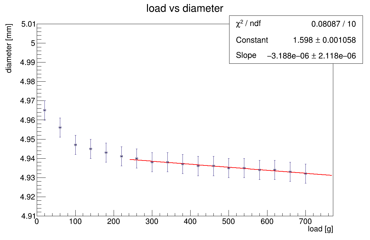
3.4 Diameter VS load VS over-presure
Another very useful study is to monitor the straw tube diameter dependence on an external load for different internal over-pressure. Results of such test for 1.34-m-long tubes when 0.5 bar and 1.0 bar over-pressure delivered into the straw are represented in Figure 13.
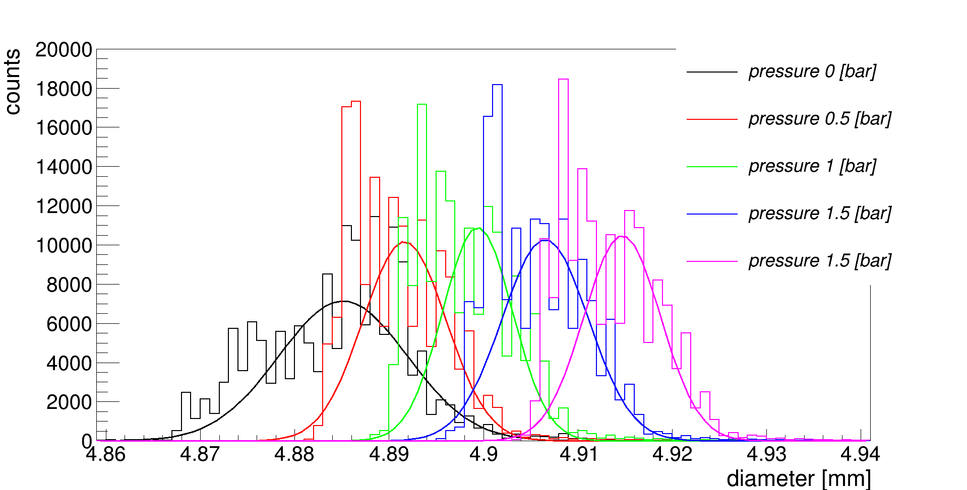
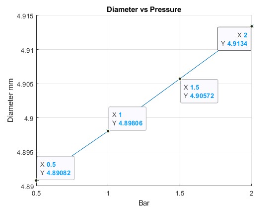
The dependence of the straw diameter on over-pressure was already shown in Figure 5. In this chapter, the Figure 14 present the dependence of the straw tube diameter on internal over-pressure also.
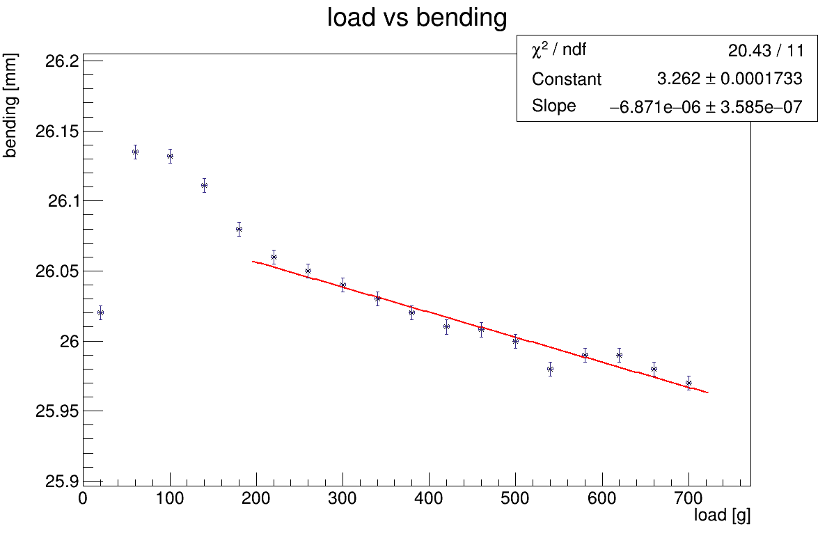
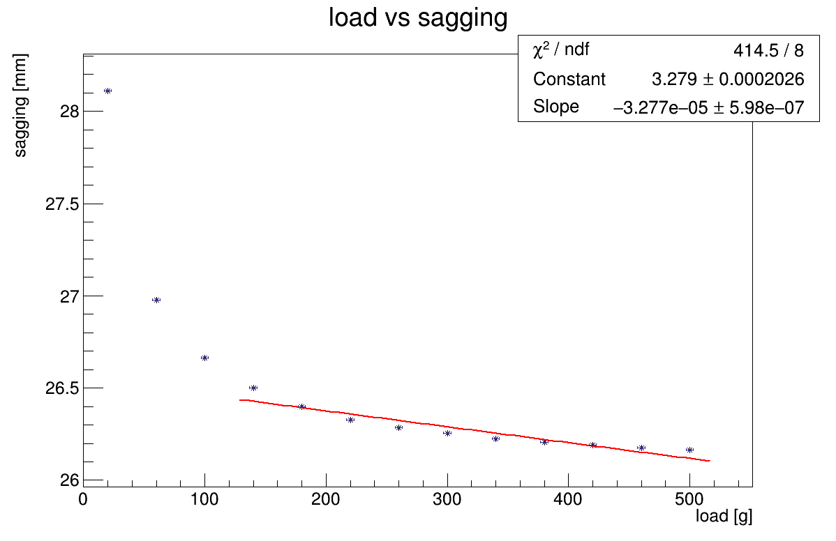
3.5 Straw tube sagging dependence on external load
The bending for the 1.34-m-long straw was done for vertical installation and only top end was fixed. The result for this measurements is presented in Figure 15a
The sagging for the 1.34-m-long straw was done in horizontal installation and, again, only one side fixed but other side was loaded. The result of this measurements is presented in Figure 15b.
4 Conclusions
The 5-mm 12--thick straw tube production methodology and production station was successfully developed. More then 100 straws were produced to prove production stability.
To carry out the mechanical testing of the tubes various special test setups were created and different methodologies used. Using this setups a detailed properties studies of the straws were performed: elongation, diameter changes over pressure and load, bending and sagging.
The elongation study shows that these straw could be loaded with up to 600 gram and it still stay within of the stretching linear area. The Young module was calculated to about 6.2 GPa.
The straw elongation caused by internal over-pressure proportionally depends on the internal over-pressure. Stiffness for 0.5-m-long straw was found to be twice higher then for 1-m-long straw as it was expected.
As expected, diameter also depends on the external load to straw and internal over-pressure value. But the diameter variation is within 14 limits.
Sagging study shows that it is necessary to load at least 200 gram to minimize sagging of the 1.34-m-long straw at center to 0.1 to minimize the gravitation effects on straw. This result is important for the straw installed horizontally. Bending study for the same straw on vertical installation shows that it is necessary to load with same 200 gram to hold the displacement of the straw within of 0.1 .
During testing it’s experimentally confirmed that straws with this design could hold up to 3 bar over-pressure. This fact allows to use the straws with wall of 12 for COMET Phase-II with 1 bar over-pressure delivered and operated in vacuum.
5 Acknowledgments
This work was made possible by the generous support from SRNSFG (Georgia). Their belief in our research and the provision of a grant [PHDF-19-3553] significantly contributed to the successful execution of this research.
The authors would like to express their sincere gratitude to GTU (Tbilisi, Georgia) and JINR (Dubna. Russia) for strong facility support to perform this study.
Also we would like to express our sincere gratitude to KEK/J-PARC (Japan) for our support according to grant [???].
We also thank to Iliya Chokheli for supporting this research providing the design of CAD models and it development for the test setup.
References
- [1] The COMET Collaboration, R. Abramishvili and other “COMET Phase-I technical design report” In Progress of Theoretical and Experimental Physics 2020.3, 2020, pp. 033C01 DOI: 10.1093/ptep/ptz125
- [2] E.P. Hincks and B. Pontecorvo “Search for Gamma-Radiation in the 2.2-Microsecond Meson Decay Process” In Phys. Rev. 73, 1947, pp. 257 DOI: 10.1103/PhysRev.73.257
- [3] R. Barbieri and L.J. Hall “Signals for supersymmetric unification” In Physics Letters B 338.2, 1994, pp. 212–218 DOI: 10.1016/0370-2693(94)91368-4
- [4] Y. Kuno and Okada “Muon decay and physics beyond the standard model” In Rev. Mod. Phys. 73, 2001, pp. 151 DOI: 10.1103/RevModPhys.73.151
- [5] S. Mihara, J.P. Miller, P. Paradisi and G. Piredda “Charged Lepton Flavor-Violation Experiments” In Annu. Rev. Nucl. Part. Sci. 63, 2013, pp. 531 DOI: 10.1146/annurev-nucl-102912-144530
- [6] C. Lu et al. “Proposal to the SSC Laboratory for Research and Development of a Straw-Tube Tracking Subsystem”, 1989
- [7] Leonard Schieber “A Straw Tube Design Suitable for Mass Production” In Supercollider 2 Boston, MA: Springer US, 1990, pp. 699–706 DOI: 10.1007/978-1-4615-3728-1˙64
- [8] V.N. Bychkov and al. “The large size straw drift chambers of the COMPASS experiment” In Nuclear Instruments and Methods in Physics Research Section A: Accelerators, Spectrometers, Detectors and Associated Equipment 556.1, 2006, pp. 66–79 DOI: 10.1016/j.nima.2005.10.026
- [9] W. Erni and al “Technical design report for the PANDA (AntiProton Annihilations at Darmstadt) Straw Tube Tracker” In The European Physical Journal A 49.2, 2013, pp. 25 DOI: 10.1140/epja/i2013-13025-8
- [10] The ATLAS collaboration “Technical Design Report for the Phase-II Upgrade of the ATLAS TDAQ System” In Nuclear Instruments and Methods in Physics Research Section A: Accelerators, Spectrometers, Detectors and Associated Equipment 556.1, 2006, pp. 66–79 DOI: 10.17181/CERN.2LBB.4IAL
- [11] MyeongJae Lee “The Straw-tube Tracker for the Mu2e Experiment” 37th International Conference on High Energy Physics (ICHEP) In Nuclear and Particle Physics Proceedings 273-275, 2016, pp. 2530–2532 DOI: 10.1016/j.nuclphysbps.2015.09.448
- [12] A. Sergi “NA62 Spectrometer: A Low Mass Straw Tracker” Proceedings of the 2nd International Conference on Technology and Instrumentation in Particle Physics (TIPP 2011) In Physics Procedia 37, 2012, pp. 530–534 DOI: 10.1016/j.phpro.2012.03.713
- [13] Hagime Nishiguchi “Construction on vacuum-compatible straw tracker for COMET Phase-I” In Nucl. Instrum. Meth. A 958, 2020, pp. 162800 DOI: 10.1016/j.nima.2019.162800
- [14] Yoshinori Fukao “Construction Status of the COMET Experimental Facility” In 12th International Particle Accelerator Conference, 2021, pp. 3 DOI: 10.18429/JACoW-IPAC2021-TUPAB210
- [15] H. Nishiguchi and al “Vacuum-Compatible, Ultra-Thin-Wall Straw Tracker; Detector construction, Thinner straw R&D, and the brand-new graphite-straw development” In Nucl. Instrum. Methods Phys. Res. A 1042, 2022, pp. 167373 DOI: 10.1016/j.nima.2022.167373
- [16] Hagime Nishiguchi and other “Development of an extremely thin-wall straw tracker operational in vacuum–The COMET straw tracker system” In Nuclear Instruments and Methods in Physics Research Section A 845, 2017, pp. 269–272 DOI: 10.1016/j.nima.2016.06.082
- [17] Sergey Movchan “Straw tracker prototype for the precise measurement of the very rare decay (NA62 experiment at SPS CERN)” PSD8 In Nuclear Instruments and Methods in Physics Research Section A: Accelerators, Spectrometers, Detectors and Associated Equipment 604.1, 2009, pp. 307–309 DOI: 10.1016/j.nima.2009.01.223
- [18] N. Azorskiy and other “A drift chamber with a new type of straws for operation in vacuum” Frontier Detectors for Frontier Physics: Proceedings of the 13th Pisa Meeting on Advanced Detectors In Nuclear Instruments and Methods in Physics Research Section A: Accelerators, Spectrometers, Detectors and Associated Equipment 824, 2016, pp. 569–570 DOI: 10.1016/j.nima.2015.11.112
- [19] N. Tsverava et al. “Development of Ultrathin 12 Thick Straw Tubes for the Tracking Detector of COMET Experiment” In 2019 IEEE Nuclear Science Symposium and Medical Imaging Conference (NSS/MIC), 2019 DOI: 10.1109/NSS/MIC42101.2019.9060032
- [20] Levan Glonti, Temur Enik and other “Longitudinal Tension and Mechanical Stability of a Pressurized Straw Tube” In Instruments 2.4, 2018 DOI: 10.3390/instruments2040027
- [21] MICRO-EPSILON Eltrotec GmbH , Göppingen, Germany “Catalog optoCONTROL Optical micrometer” (accessed on 03/12/2024), https://www.micro-epsilon.in/fileadmin/download/products/cat–optoCONTROL-ODC–en.pdf
- [22] Herbert Becker “Elastic modulus of Mylar sheet” In Journal of Applied Polymer Science 9, 1965, pp. 911–916 DOI: 10.1002/app.1965.070090309