Enhancing Indoor and Outdoor THz Communications with Beyond Diagonal-IRS: Optimization and Performance Analysis
Abstract
This work investigates the application of Beyond Diagonal Intelligent Reflective Surface (BD-IRS) to enhance THz downlink communication systems, operating in a hybrid: reflective and transmissive mode, to simultaneously provide services to indoor and outdoor users. We propose an optimization framework that jointly optimizes the beamforming vectors and phase shifts in the hybrid reflective/transmissive mode, aiming to maximize the system sum rate. To tackle the challenges in solving the joint design problem, we employ the conjugate gradient method and propose an iterative algorithm that successively optimizes the hybrid beamforming vectors and the phase shifts. Through comprehensive numerical simulations, our findings demonstrate a significant improvement in rate when compared to existing benchmark schemes, including time- and frequency-divided approaches, by approximately and respectively. This underscores the significant influence of IRS elements on system performance relative to that of base station antennas, highlighting their pivotal role in advancing the communication system efficacy.
Index Terms:
Terahertz Communications, Intelligent Reflective Surfaces, Hybrid Beamforming Optimization, Indoor-Outdoor Wireless ConnectivityI Introduction
In the realm of future wireless communications, including beyond 5G (B5G) and 6G technologies, there is a drive to establish higher performance benchmarks and introduce novel application scenarios for societal digitization [1]. Terahertz (THz) communication has received considerable attention for its potential to deliver ultra-high data rates, thereby addressing the spectrum scarcity and capacity limitations faced by current communication systems[2]. Despite its promise, the adoption of THz technology faces significant challenges due to the inherent properties of THz, such as severe attenuation by molecular absorption and limited penetration through wall/obstacle, which are characteristic of high-frequency propagation[3]. To overcome these challenges, intelligent reflecting surfaces (IRS) emerge as a potential solution capable of adjusting their amplitude and phase to intelligently redirect signal transmission, thereby enhancing signal strength and coverage [4][5].
To fully exploit the advantages of IRS technology in THz communications, the creation of a virtual direct link is essential for improving signal reception and minimizing signal obstruction. In the study by [6], the optimization of the weighted sum rate in an IRS-assisted multi-user THz MIMO system, utilizing Orthogonal Frequency Division Multiple Access (OFDMA), is explored. This involves the joint optimization of hybrid beamforming and IRS phase shifts. Concurrently, [2] investigates an IRS-assisted simultaneous wireless information and power transfer (SWIPT) design in secure THz systems and proposes a robust beamforming strategy that minimizes total transmit power. This strategy optimizes both transmit beamforming and IRS phase shifts while ensuring compliance with outage rate probability constraints. The authors of [7] focus on optimizing UAV deployment, power, and bandwidth allocation in THz UAV-assisted wireless systems to reduce transmission delays. The authors of [8] examine secure transmission in THz-enabled RIS-assisted Non-Terrestrial Networks (NTN), deriving an approximate expression for the ergodic secrecy rate (ESR) while considering various impairments such as atmospheric turbulence and phase errors.
Despite these advancements, a significant gap exists in the literature regarding the provision of simultaneous service to both indoor and outdoor users in THz communication networks because of the large attenuation that THz experiences in buildings compared to lower frequency bands. This is critical as a considerable amount of mobile data traffic, estimated to be between and , is consumed indoors due to the prevalent indoor lifestyle of users [9, 10]. This underscores the need for efficient outdoor-to-indoor communication solutions. Previous works, such as those by [11, 12, 13], have spurred the development of efficient architectural designs, with key contributions in channel modeling and measurement for indoor THz and sub-THz communications. Related works in, [14, 15], have made significant contributions to this area, with a primary focus on low-frequency bands and the deployment of multiple IRS units, which however may not align with the principles of resource efficiency.
Addressing the aforementioned challenges and gaps, this study introduces a novel approach by proposing the use of a Beyond Diagonal Intelligent Reflective Surface (BD-IRS) operating in the hybrid mode, which integrates both reflective and transmission functionalities. This configuration allows for the simultaneous servicing of both indoor and outdoor users by efficiently reflecting and transmitting signals, thereby optimizing resource utilization and enhancing overall network performance. Following that, the main contributions of this letter are summarized as follows:
-
•
We develop a joint optimization framework aimed at facilitating simultaneous service to both indoor and outdoor users. This is achieved by jointly optimizing the hybrid beamforming vectors at the THz base station (BS) and the phase shifts of the BD-IRS operating in the hybrid mode.
-
•
To address the optimization challenge, we decompose the original problem into sub-problems, focusing on the hybrid beamforming and IRS phase shift control. These are tackled iteratively using the Block Coordinate Descent (BCD) method, allowing for a systematic solution to the original complex optimization problem.
-
•
Our results indicate that the proposed approach significantly outperforms existing benchmark schemes, with improvements in rate of approximately 30.50% and 70.28% over the time- and frequency-division approaches, respectively, thereby highlighting the critical impact of IRS elements on system performance compared to BS antennas.
The letter is structured as follows: Section II details the system model and problem formulation. Section III outlines the proposed solution. Numerical results are presented in Section IV, followed by conclusions in Section V.
II System Model
II-A Network Architecture
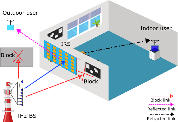
This study explores the application of BD-IRS to enhance THz downlink communication systems to provide service to single-antenna indoor and outdoor users, denoted as , as depicted in Fig. 1. The THz base station (BS) is equipped with antennas and RF chains where . It is noteworthy that the number of users served is inherently limited by the number of RF chains. BD-IRS comprises of elements and is denoted by . Users are divided into two distinct groups based on their physical location: reflective (outdoor) users, indexed by , and transmissive (indoor) users, indexed by . Under the assumption of perfect channel state information (CSI) acquisition achieved through channel estimation techniques [16], this scenario posits an upper-bound solution. Since the number of RF chains is fewer than the number of antennas, a hybrid beamforming design must be adopted. The hybrid beamforming architecture entails initial signal processing via a digital beamformer , followed by an analog beamformer . Furthermore, due to the blockage, the BS can only transmit data to the users via the BD-IRS operating in a hybrid mode, wherein it concurrently reflects and transmits the signal to the intended user. Within this context, the BD-IRS’s scattering matrix can be denoted as , where the index signifies the transmissive and reflective aspects, respectively, subject to the constraint , which ensures energy conservation in both reflection and transmission processes. The received signal at the -th user is given as follows:
| (1) |
where if and if . In (1), the beamforming vector represents the composite beamforming effect for the -th user. The channel vectors and represent the channel from the IRS to the user and from the BS to the IRS, respectively. The transmitted signal for the -th user, , adheres to the condition , and the additive white Gaussian noise at the user is denoted by . Given the substantially lower power gain of non-line-of-sight (NLoS) paths compared to line-of-sight (LoS) paths in THz communications, this analysis primarily concentrates on the LoS channel model[2]. Hence, the channel is modeled as , where encapsulates the effects of free-space path loss and medium absorption. Here, signifies the speed of light, is the carrier frequency, represents the distance from the BS to the IRS, and is the medium’s absorption coefficient obtained from the high-resolution transmission (HITRAN) database [17]. The antenna array response vectors at the transmitter and IRS are represented by , defined for the respective angles of arrival and departure.
| (2) | ||||
| (3) |
Here, , with representing the antenna spacing, and denoting the angle of departure (AoD) and angle of arrival (AoA), respectively. The channel vector is similarly expressed as:
| (4) |
Here denotes the distance between the IRS and users. Moreover, the signal-to-interference plus noise ratio (SINR) of th user can be expressed as
| (5) |
II-B Problem Formulation
In this work, we aim to maximize the sum rate of the users by jointly optimizing the hybrid beamforming vector , followed by an IRS scattering matrix . Formulating the joint optimization problem as such:
| (6a) | ||||
| s.t. | (6b) | |||
| (6c) | ||||
| (6d) | ||||
where is given in (5), denotes the maximum allowable transmit power at the BS, the optimization problem presented in (6) poses substantial challenges because of non-convex constraints associated with the unitary nature of the IRS and the nonlinearity of the objective function, as well as the coupling of variables detailed in (6c). To navigate these complexities effectively, we reformulate the optimization problem into a more manageable form by leveraging fractional programming techniques. Following this, an iterative method is employed to resolve the reformulated problem efficiently. This approach facilitates a systematic enhancement of the sum rate for the users, achieved through the meticulous optimization of both the hybrid beamforming vector and the IRS scattering matrix.
III Proposed Solution
This section delineates our proposed framework, wherein we initially render the objective function more tractable by introducing auxiliary variables and . Employing a quadratic transformation to convert the fractional SINR terms into an integer expression, we reformulate the objective function (6a) as follows [18]:
| (7) |
where is the shorthand notation of the variables, , and ; . Subsequently, we express the new optimization problem as:
| (8a) | |||
Considering the problem’s multivariable complexity as delineated in (8), we adopt the block coordinate descent method to segregate it into distinct subproblems. These subproblems are then addressed iteratively, with detailed explanations provided in the subsequent subsections.
III-A Auxiliary Parameter Optimization
For the current estimates of , , and , we directly optimize and in the convex framework of (8). Setting the derivatives and yields the optimal auxiliary variables: and .
III-B Hybrid Beamforming
In the realm of hybrid beamforming, the convexity of the optimization framework (7) facilitates the formulation of the optimization problem for and as follows:
| (9a) | ||||
| s.t. | (9b) | |||
| (9c) | ||||
Despite the objective function’s convexity, the coupling of decision variables presents a challenge to deriving optimal solutions. To mitigate this, subproblems are formulated, with a subset of variables being held constant as each subproblem is solved iteratively. Hence, the analog beamforming subproblem is specified as follows:
| (10a) | |||
Similarly, the subproblem for digital beamforming is outlined as:
| (11a) | |||
Subproblems (10) and (11) are convex and hence can be solved iteratively using standard optimization tools, e.g., CVX.
III-C IRS Phase Shift Optimization
Given , , and , we optimize and as follows:
| (12a) | ||||
| s.t. | ||||
where , , and for . This leads to an objective function as:
| (13) |
Simplifying, and ,and the subproblem for becomes:
| (14a) | ||||
| s.t. | (14b) | |||
Utilizing the conjugate gradient method, this strategy leverages the Intelligent Reflective Surface (IRS) elements to streamline the optimization of phase shifts. The initial step involves computing the Euclidean gradient of (14a), expressed as . This computation aids in determining the Riemannian gradient at , formulated as: . The Riemannian gradient, , then facilitates the calculation of the rotation matrix , with serving as the control parameter for convergence. This rotation matrix is subsequently employed to iteratively update the IRS phase shift matrix as . Algorithm 1 outlines its operations and sets the worst case per iteration complexity at , with and as the maximum iterations for hybrid beamforming and the conjugate gradient method, respectively. The function demonstrates that iteratively converges towards a local optimum, with the pursuit of the global maximum identified as an area for further research.
| Parameter | Value | Parameter | Value |
|---|---|---|---|
| Area Length | meters | N | 4 |
| Thz | B | 1MHz | |
| -174 dBm/Hz | K | [25-100] | |
| [49-225] | [15-30] dBm |

IV Performance Evaluation
In this section, the performance of a proposed BD-IRS to enhance THz communication systems is evaluated. We compare the proposed hybrid transmissive/reflective design with two reference schemes: TDMA and FDMA. In the former, the IRS consecutively switches between transmissive and reflective mode to serve all the users. In the latter, two user groups are simultaneously served in two orthogonal frequency bandwidths. Furthermore, the analysis examines the impact of various simulation parameters, including the IRS performance across different frequency bands. Simulation parameters are listed in Table I.
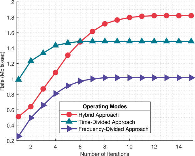
The proposed scheme’s effectiveness is determined by the algorithm’s convergence. Through extensive simulation, average results are generated and plotted across different operating modes over iterations. Fig. 2 shows that, as the algorithm iterates, it converges to a stable point by setting and . Notably, the proposed scheme outperforms other schemes due to limitations in reflective and transmissive IRS configurations respectively. Time-divided allows reflective and transmissive users to receive signals at different intervals, whereas frequency-division serves both user groups concurrently but at different bandwidths. In contrast, our approach allows for simultaneous service provision to both user sets, resulting in a higher average rate than alternatives.
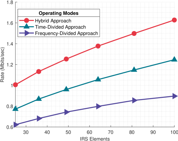
The comparative analysis, illustrated in Fig. 3 under consistent settings, evaluates the efficacy of the proposed scheme against time-divided and frequency-divided strategies across a range of IRS element counts. The findings underscore the distinct advantage of the proposed approach, which surpasses the time-divided and frequency-divided methods by approximately 30.50% and 70.28%, respectively, demonstrating its notable superiority.
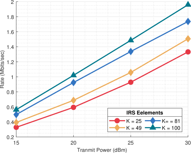
Fig. 4 illustrates the influence of transmit power and IRS elements on the system’s performance. The results reveal that both factors contribute to enhancing system performance. Notably, increasing power levels exhibit a more pronounced effect on system performance compared to escalating the number of IRS elements. Specifically, power levels exhibit an average percentage increase of , while the increase attributable to IRS elements is approximately .
Fig. 5 showcases the effects of carrier frequency and the number of BS antennas or IRS elements on system performance. The findings in 5a indicate that an increase in carrier frequency leads to higher absorption path loss, resulting in decreased performance. On average, an increase in carrier frequency leads to a system performance change of about , whereas increasing the number of antennas results in an average performance improvement of approximately . This underscores the beneficial role of additional antennas in enhancing system performance. Similarly, 5(b) presents consistent trends with varying numbers of IRS elements. Here, carrier frequency changes bring about a performance change of roughly , and increasing the number of IRS elements leads to an average performance improvement of approximately demonstrating its effectiveness as compared to BS antennas.
V Conclusion
In conclusion, this research delineates the efficacy of implementing BD-IRS in a hybrid operational mode to enhance THz downlink communications and provide simultaneous service to both indoor and outdoor single-antenna users. For this, we formulate the joint optimization problem for hybrid beamforming at the THz BS along with the BD-IRS phase shifts to maximize the sum rate. Leveraging the conjugate gradient method, the research meticulously navigates the complexities of the optimization landscape, presenting a coherent strategy for addressing these challenges. Through rigorous numerical simulations, the results affirm the proposed method’s substantial enhancement in system performance compared to traditional benchmarks, including time- and frequency-divided approaches, by demonstrating significant improvements in terms of rate by approximately 30.50% and 70.28%, respectively. This conclusive evidence underlines the proposed approach’s efficacy and establishes a robust foundation for future advancements in THz communication networks. Future work may explore imperfect CSI and hardware limitations while enhancing energy efficiency in multi-user scenarios.
References
- [1] I. F. Akyildiz, C. Han, Z. Hu, S. Nie, and J. M. Jornet, “Terahertz band communication: An old problem revisited and research directions for the next decade,” IEEE Transactions on Communications, vol. 70, no. 6, pp. 4250–4285, 2022.
- [2] Z. Zhu, J. Xu, G. Sun, W. Hao, Z. Chu, C. Pan, and I. Lee, “Robust beamforming design for IRS-aided secure SWIPT terahertz systems with non-linear EH model,” IEEE Wireless Communications Letters, vol. 11, no. 4, pp. 746–750, 2022.
- [3] C. Han, Y. Wu, Z. Chen, Y. Chen, and G. Wang, “THz ISAC: A physical-layer perspective of terahertz integrated sensing and communication,” IEEE communications magazine, vol. 62, no. 2, pp. 102–108, 2024.
- [4] H. Zhang and B. Di, “Intelligent omni-surfaces: Simultaneous refraction and reflection for full-dimensional wireless communications,” IEEE Communications Surveys & Tutorials, no. 4, pp. 1997–2028, 2022.
- [5] A. Mahmood, T. X. Vu, W. U. Khan, S. Chatzinotas, and B. Ottersten, “Joint Computation and Communication Resource Optimization for Beyond Diagonal UAV-IRS Empowered MEC Networks,” arXiv preprint arXiv:2311.07199, 2023.
- [6] W. Hao, G. Sun, M. Zeng, Z. Chu, Z. Zhu, O. A. Dobre, and P. Xiao, “Robust design for intelligent reflecting surface-assisted MIMO-OFDMA terahertz IoT networks,” IEEE Internet of Things Journal, vol. 8, no. 16, pp. 13 052–13 064, 2021.
- [7] L. Xu, M. Chen, M. Chen, Z. Yang, C. Chaccour, W. Saad, and C. S. Hong, “Joint location, bandwidth and power optimization for THz-enabled UAV communications,” IEEE Communications Letters, vol. 25, no. 6, pp. 1984–1988, 2021.
- [8] J. Yuan, G. Chen, M. Wen, R. Tafazolli, and E. Panayirci, “Secure transmission for THz-empowered RIS-assisted non-terrestrial networks,” IEEE transactions on vehicular technology, 2022.
- [9] Huawei. Indoor digitalization with full connectivity. [Online]. Available: {https://carrier.huawei.com/en/trends-and-insights/emsite/indoor-digitalization-with-full-connectivity}
- [10] Cisco. Cisco vision: 5g – thriving indoors whitepaper. [Online]. Available: {https://www.cisco.com/c/dam/en/us/solutions/collateral/service-provider/ultra-services-platform/5g-ran-indoor.pdf}
- [11] Y. Chen, Y. Li, C. Han, Z. Yu, and G. Wang, “Channel measurement and ray-tracing-statistical hybrid modeling for low-terahertz indoor communications,” IEEE Transactions on Wireless Communications, vol. 20, no. 12, pp. 8163–8176, 2021.
- [12] Y. Xing, T. S. Rappaport, and A. Ghosh, “Millimeter wave and sub-THz indoor radio propagation channel measurements, models, and comparisons in an office environment,” IEEE Communications Letters, vol. 25, no. 10, pp. 3151–3155, 2021.
- [13] Y. Chen, C. Han, Z. Yu, and G. Wang, “Channel measurement, characterization and modeling for terahertz indoor communications above 200 ghz,” IEEE Transactions on Wireless Communications, 2023.
- [14] I. Yildirim, A. Uyrus, and E. Basar, “Modeling and analysis of reconfigurable intelligent surfaces for indoor and outdoor applications in future wireless networks,” IEEE transactions on communications, vol. 69, no. 2, pp. 1290–1301, 2020.
- [15] M. H. N. Shaikh, V. A. Bohara, A. Srivastava, and G. Ghatak, “An energy efficient dual IRS-aided outdoor-to-indoor communication system,” IEEE Systems Journal, 2023.
- [16] F. Zhao, W. Hao, X. You, Y. Wang, Z. Chu, and P. Xiao, “Joint Beamforming Optimization for IRS-aided THz Communication With Time Delays,” IEEE wireless communications letters, 2023.
- [17] L. S. Rothman, I. E. Gordon, A. Barbe, D. C. Benner, P. F. Bernath, M. Birk, V. Boudon, L. R. Brown, A. Campargue, J.-P. Champion et al., “The HITRAN 2008 molecular spectroscopic database,” Journal of Quantitative Spectroscopy and Radiative Transfer, pp. 533–572, 2009.
- [18] K. Shen and W. Yu, “Fractional programming for communication systems—part i: Power control and beamforming,” IEEE Transactions on Signal Processing, vol. 66, no. 10, pp. 2616–2630, 2018.