Aerial Robots Carrying Flexible Cables: Dynamic Shape Optimal Control via Spectral Method Model
††thanks: 1 Robotics and Mechatronics Department, Electrical Engineering, Mathematics, and Computer Science (EEMCS) Faculty, University of Twente, 7500 AE Enschede, The Netherlands.
††thanks: 2 Department of Computer, Control and Management Engineering, Sapienza University of Rome, 00185 Rome, Italy.
††thanks: This work was partially funded by the European Commission Horizon Europe Framework under project Autoassess (101120732) and MSCA PF Flyflic (101059875), and by the China Scholarship Council (202206290005).
Abstract
In this work, we present a model-based optimal boundary control design for an aerial robotic system composed of a quadrotor carrying a flexible cable. The whole system is modeled by partial differential equations (PDEs) combined with boundary conditions described by ordinary differential equations (ODEs). The proper orthogonal decomposition (POD) method is adopted to project the original infinite-dimensional system on a subspace spanned by orthogonal basis functions. Based on the reduced order model, nonlinear model predictive control (NMPC) is implemented online to realize shape trajectory tracking of the flexible cable in an optimal predictive fashion. The proposed reduced modeling and optimal control paradigms are numerically verified against an accurate high-dimensional FDM-based model in different scenarios and the controller’s superior performance is shown compared to an optimally tuned PID controller.
Index Terms:
Aerial Systems: Mechanics and Control, Motion Control, Mobile Manipulation, Aerial ManipulationI Introduction
Recently, uncrewed aerial vehicles (UAVs), also known as aerial robots, have attracted significant attention due to their huge potential applications in areas such as search and rescue, agriculture, transportation, or even inspection and manufacturing. Among this large number of scenarios, aerial vehicles may need to interact with deformable objects, for example, when transporting suspended cargo through a cable [1, 2, 3, 4, 5] or when performing refueling operations using flexible pipes [6, 7, 8, 9]. In these cases, an aerial vehicle manipulates a flexible cable through just one contact point. Due to the flexible characteristic of the cable, modeling and control for such a soft aerial manipulation system are different from those used in conventional rigid aerial manipulation [10, 11].
For analyzing and synthesizing these aerial vehicle-cable systems, several mathematical models have been proposed in the robotics community. After that, different control laws and planning methods were designed based on each model. The model of the aerial vehicle-cable system could be generally divided into five categories: single rigid pendulum model, single elastic pendulum model, series of rigid links model, series of elastic links model, and distributed parameter model.
1) Single rigid pendulum: Palunko et al. consider a system composed of a quadrotor and a cable-suspended load, they model it as a single pendulum attached to the aerial vehicle, in which the cable is massless and non-elastic and the load is represented as a point mass [12]. Based on this 3D single pendulum, they adopt a dynamic programming approach to generate a swing-free trajectory [12]. The same model is also used in [13], where the motion of the pendulum is regarded as a disturbance, and feedback linearization control is used. Furthermore, this single rigid pendulum model is used to solve planning and control problems in single multi-rotor suspended payload transportation [14, 15] and quadrotors cooperative transportation [16, 17, 18]. In [19] and [20], the system is modeled using two subsystems, one in which the cable is taut and in which it is slack, each subsystem is proved to be differentially flat, which is used for trajectory generation. Hence, a hierarchical controller is designed to track the planned trajectories.
2) Single elastic pendulum: Cable models that neglect the bending but allow for changes in the length via elasticity have been also adopted in the literature. In [21] and [22], a point mass is suspended below a single quadrotor, while a rigid body manipulated by multiple quadrotors through elastic cables is considered in [23] and [24]. Controllers for tracking the payload’s pose are designed on a simplified model disregarding elasticity and are proven to work in the elastic case as well. In [25, 26, 27] admittance-based control not relying on direct communication is used to regulate the pose of a payload suspended below elastic cables.
3) Series of rigid links: To include the flexibility of the cable in the model, Goodarzi et al. use a finite series of rigid links (multiple pendulum model) to describe the behavior of the cable, inextensible mass-less links are connected by passive spherical joints, where the mass is concentrated [28]. A similar discretized model is also used to model the motion of the aerial refueling hose [6]. In [29, 30], Kotaru et al. prove the differential flatness of different systems composed by aerial vehicles manipulating a cable modeled with a series of rigid links, and they use linear quadratic regulation (LQR) to control these systems. Instead of using lumped mass link models, Quisenberry et al. use distributed mass links to model the cable [31].
4) Series of elastic links: Series of elastic links are adopted to consider the flexibility, elasticity, and length variation of the cable in the tethered aerial system [9]. Based on this lumped-mass model, [9] uses dynamic surface control (DSC) to control the position of a suspended load. A similar cable model has been considered in [32] for a two-robot cable system.
5) Distributed parameters model: Different from the discretized models seen so far, Liu et al. use a distributed parameter model represented by partial differential equations to describe the motion of the hose in an aerial refueling system in the longitudinal plane [7], and a backstepping approach is adopted to suppress the vibration of the hose. In [8], Liu et al. use an adaptive neural network to handle the model uncertainties.
To summarize, while single pendulum models may simplify well the dynamics of the aerial cable-suspended manipulation system when a payload of considerable mass forces the cable into a straight configuration, more complex models have been used in the literature to capture the flexibility of the cable when the task requires it. Discrete models fail to capture accurately the dynamics of the continuously flexible cable, unless a very high number of discrete elements is used, making them computationally inefficient. Distributed-parameter models have been proposed in the literature for vibration suppression during payload transportation, but not for highly dynamic tasks in which the shape of the cable is controlled.
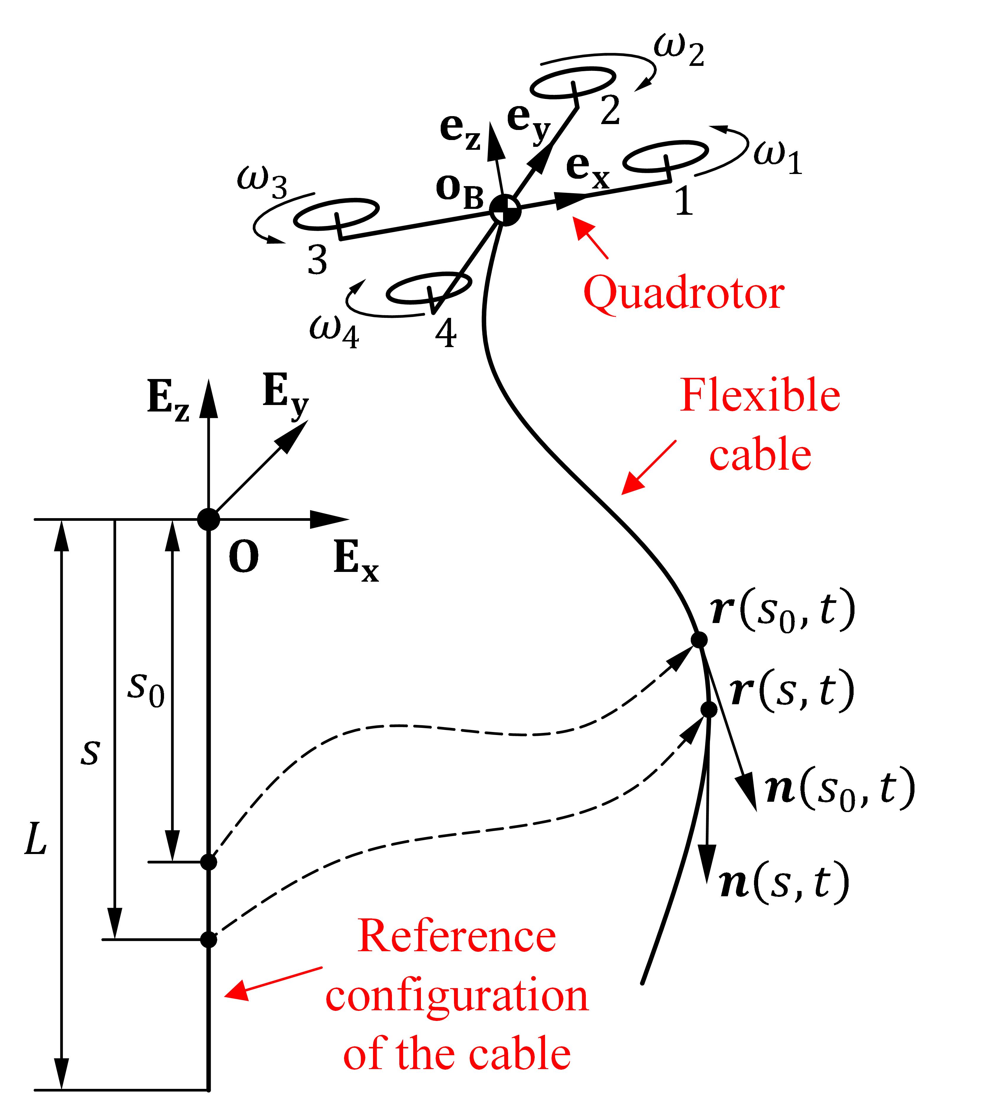
In this work, we focus on a system composed of a quadrotor carrying a flexible and extensible cable, which is illustrated in Figure 1. This work aims to control the motion of the quadrotor to let the passive cable generate different kinds of shapes. A distributed parameter model, formulated by PDEs, is used to describe the motion of the cable in 3D space. The 6-DoF motion of the quadrotor is described by ODEs, which represent one of the two boundary conditions of the cable model. For controlling this kind of PDE-ODEs hybrid system, the Proper Orthogonal Decomposition (POD) method is adopted to reduce the order of the original system. That is done by projecting the original infinite-dimensional system on a subspace spanned by orthogonal basis functions. After that, the reduced-order model is adopted as the reference system for a nonlinear model predictive control to track the cable’s shape trajectory. The contributions of this work are as follows,
-
•
A novel distributed-parameter mathematical model is presented to describe and simulate the evolution of the quadrotor-cable system accurately;
-
•
To the best of the authors’ knowledge, the spectral-decomposition method is used in this work for the first time for deriving a simplified model of the aerial vehicle-cable system that is used for the control design;
-
•
To our best knowledge, this work considers and solves for the first time the cable’s shape tracking control problem in aerial vehicle-cable systems.
This paper is organized as follows: Section II presents the derivation of the system dynamics. In Section III, the model order reduction process is derived based on the spectral method. In Section IV, NMPC-based trajectory tracking is presented. Section V shows numerical simulations that validate the proposed controller. Concluding remarks are listed in section VI.
II Mathematical Model
II-A System Description
The quadrotor-cable system in this work is illustrated in Figure 1: one endpoint of the flexible cable is attached to the center of mass (CoM) of the quadrotor. During the flight, the motion and deformation of the flexible cable are affected by its inertia, gravity, external aerodynamic forces, and the external force exerted by the robot. The work considers the following simplifying assumptions:
-
•
The air medium is homogeneous, which means the density of the air is the same everywhere;
-
•
The air medium is static, and the effect of the airflow generated by the quadrotor’s propellers on the cable is neglected;
-
•
The cable is perfectly flexible, namely, there is no torque generated when the cable is bending or twisting.
II-B System Modeling
1) Kinematics: In this section, the kinematics of the quadrotor-cable system is described. Let {, , } be a fixed orthonormal basis for the three-dimensional Euclidean space. The cable is defined as a set of elements called material points and its configuration as a curve in the world frame (absolute inertial frame), which is indicated as . Specifically, a configuration is defined as the reference (rest) configuration of the cable, in which is the coordinate of material points, and is the length of the untensioned cable. The position of the material point having coordinate (in the rest configuration) at time is denoted as . In this work, the subscripts and represent the operations and , respectively. The velocity and acceleration of the material point are denoted as and , respectively. Because one endpoint of the cable coincides with the CoM of the quadrotor, the position of the quadrotor’s CoM with respect to the world frame is . The attitude of the quadrotor is expressed by the rotation matrix from frame to quadrotor’s body-fixed frame which is shown in Figure 1. In this work, we use Tait–Bryan angles {,,} following the rotation order to represent . The angular velocity of the quadrotor body-fixed frame of the quadrotor w.r.t. the world frame expressed in the quadrotor body-fixed frame is denoted with . Its relationship with the rate of change of the Tait–Bryan angles is:
| (1) |
where .
2) Constitutive law: The contact force that the material point in position undergoes due to the action of the cable portion can be related through material constitutive laws to the mechanical strains. For more detailed information about the nonlinear elasticity of extensible cable please refer to [33]. The strains of the cable are defined as the difference between the deformed configuration and the reference configuration. In this work, the cable is considered a perfectly flexible cable, so elongation, expressed as in (2), is the only type of strain involved in the model.
| (2) |
Due to perfect flexibility, the internal force is tangent to the curve at and is expressed as
| (3) |
where is the cable’s tension at point . In this work, we consider the cable is linearly elastic, and so the tension is denoted as
| (4) |
where and are Young’s modulus and the cross-sectional area of the cable, respectively.
3) Aerodynamic load and gravitational force: During motion, the cable is subject to two different external forces: aerodynamic drag and gravitational force. The aerodynamic drag acting on the material point with configuration at time (which we indicate as point ) is proportional to the square of the velocity vector and is directed in the opposite direction. The expression of the aerodynamic drag is given by
| (5) |
in which is the air density, is the aerodynamic drag coefficient, and we omitted the dependency of .
The gravitational force that the cable undergoes at point is
| (6) |
in which is the density of the cable and is the value of acceleration of gravity.
4) Equations of motion: Consider now a segment of the cable. According to the law of conservation of momentum, the motion of the selected segment follows the following integral form:
| (7) | |||
After differentiating (7) with respect to , the equations of motion of the cable are obtained as
| (8) |
The equations of motion of the quadrotor are derived using the Newton-Euler approach:
| (9) |
in which is the mass of the quadrotor, is rotational inertia matrix w.r.t. and expressed in the frame , is the sum of the input and external forces applied to the quadrotor’s CoM, expressed in the world frame, and the total input torque, expressed in the body-fixed frame. The expression of is shown in (10) and is composed of two parts: the thrust input force generated by the four propellers and the interaction force generated by the flexible cable:
| (10) |
where is the thrust force generated by the propeller, with and the thrust coefficient and intensity of rotational velocity of the propeller, respectively.
The expression of is shown as (11), where is the position of the propeller in the quadrotor’s body-fixed frame and is the drag coefficient [34].
| (11) |
II-C Finite Difference Method
The finite difference method (FDM) is adopted to simulate the quadrotor-cable system by solving the partial differential equations (PDEs) (12) combined with boundary conditions in (13)-(15) and initial conditions which are , , ,,} and , , (where and are the initial Tait–Bryan angles of the quadrotor and their time derivatives).
In the following, the procedure for solving (12)-(15) is introduced. Firstly, the solution domain is discretized in space. Hence, the cable is discretized into intervals of length along direction, and the motion of these intervals is described by the position, velocity, and acceleration of their nodes (i.e., endpoints): , and , in which . After that, the deformation of the cable can be approximately described by the difference operation of nodes shown as (16)-(18):
| (16) |
| (17) |
| (18) | |||
where, , and the expression of is as in (19), which satisfies the boundary condition (15) is
| (19) |
After substituting (16)-(18) into (12), the motion equation of each node is obtained as
| (20) | |||
in which .
The dynamics of the node in position coincide with the translational dynamics of the quadrotor. That is described by (13), where the contact force applied on the quadrotor by the cable is computed from (7) (in which ) via numerical integration in the domain of , obtaining:
| (21) |
| (22) |
| (23) | |||
The evolution of the motion and deformation of the flexible cable described by ordinary differential equations (ODEs) (20) and (23) is numerically simulated via fourth-order Runge-Kutta method which is also adopted to numerically solve the attitudinal dynamics of the quadrotor described by (14). In this case, the system described by the state {} is simulated under the effect of the inputs {}.
III Reduced-Order Model
Although it is possible to use (14), (20), and (23) for simulating the quadrotor-cable system, it is hard to adopt these as the plant model for control design due to the large size of the state evolving in . This work proposes to reduce the order of the model using the POD method for projecting the original infinite-dimension system (12)-(15) on a lower dimensional subspace spanned by a limited number of basis functions. POD is commonly adopted as a model order-reducing method in the field of computational fluid dynamics (CFD) [35, 36], however, at the best of our knowledge it is the first time that such a method is applied to this type of robotic systems.
In the following, the procedure for deriving the Reduced-Order Model (ROM) for the quadrotor-cable system is introduced. Firstly, the orthogonal basis functions, also called dynamic modes, of the cable are obtained from simulation data. After that, the original cable dynamics (12) is projected on the subspace linearly spanned by those basis functions. Finally, the difference between the original system and the ROM is evaluated.
III-A Cable Data Collection
For obtaining a suitable group of basis functions to describe the motion of cable, simulation data are needed. Hence, a hierarchical position tracking controller is designed for the quadrotor to run the simulations. A controller similar to the one used in [37] will be used to drive the quadrotor and excite the dynamics of the cable.
Eventually, the quadrotor follows the reference trajectory and swings the cable. For exciting the dynamics of the flexible cable, the reference position trajectory of the quadrotor is selected as a sinusoidal sweep signal in three axes of the world frame. After that, the displacement and deformation of the cable are recorded over the discrete sequence of time instants , where and are the simulation time and the sampling period, respectively. The number of time instants is denoted with . At each time instant the current shape of the cable is spatially sampled by sampling points with , where and it holds that (for obtaining all the dynamic modes of the cable during decomposition process [35]). In this work, is sampled at intervals of length equally spaced along .
Especially, the data representing the sampled cable shape evolution over time are stored as a rectangular matrix (28), where each column refers to a particular time instant and each row to a particular sampling point.
| (28) |
III-B Proper orthogonal decomposition
Similar to [35], the displacement field of the cable is assumed to be decomposed into the linear combination of POD modes and displacement of the cable tip, as shown in
| (29) |
where are the space-depending modes and are the time-depending expansion coefficients of each mode along the directions, and is the number of dynamic modes. It should be noted that these POD modes are orthonormal, which means the inner product between these modes satisfies
| (30) |
In this work, singular value decomposition (SVD) is adopted to obtain the discrete representation of POD modes of the cable from the recorded data in the following form
| (31) | ||||
where, is the the recorded cable’s tip position data at instant. And, matrix stores the differences between each recorded point position and cable’s tip position . Matrices , and , in which and contain the left and right singular vectors of , and matrix holds the singular values . After that, the POD mode is represented as column vector in which satisfies the orthonormal property shown as (32) where and is the element of vector and , respectively.
| (32) |
After that, the singular values in are used to determine the dominating POD modes from based on the ratio between energy held by each mode and total energy which can be evaluated via (33).
| (33) |
III-C Reduced Order Model
Based on the approximate representation of the cable’s displacement field, the motion and deformation of the cable can be described by the evolution of the coefficients plus the motion of cable’s endpoint . For obtaining the dynamics of these coefficients, (29) is substituted into (12), and the new expression of the cable dynamics becomes
| (34) | ||||
in which represents operation .
To reorganize the expression , both sides of (34) are multiplied by the POD mode using the scalar product definition in (30) thus obtaining
| (35) | |||
In this work, the POD modes are represented by the discrete form . To do so, the integral operations in (35) are approximately calculated through numerical integration as shown in the following (36)-(38):
| (36) |
| (37) |
| (38) |
where,
| (39) | ||||
| (40) |
The dynamics of POD modes’ coefficients are approximated by (35)-(40). The ROM of the cable is obtained by combining POD modes dynamics with the dynamics of the cable endpoint . In this case, the state of the ROM model is , and the evolution of the state is formulated as in (41), in which and the acceleration of cable’s endpoint , namely of the quadrotor CoM, is treated as the input of the ROM model.
| (41) | |||
IV Optimal Controller Design
In the previous section, we derived the ROM for the original cable dynamics described by PDEs. In this section, the ROM is used in a Nonlinear Model Predictive Control (NMPC) framework for realizing quadrotor-cable system regulation control and cable shape trajectory tracking control.
IV-A Control architecture
The structure of the cable shape trajectory tracking controller for the quadrotor-cable system is illustrated in Fig. 2. The controller is mainly composed of two layers: quadrotor attitude controller (inner loop) and NMPC (outer loop), which receives the reference trajectory from the trajectory planner.
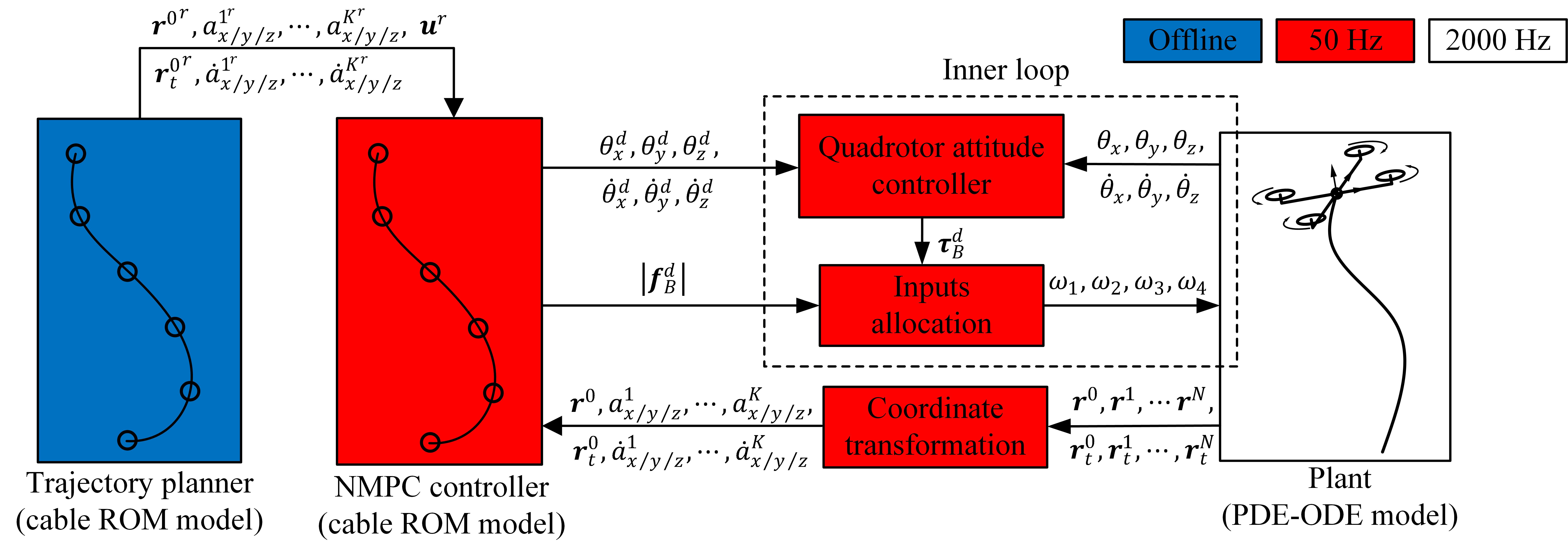
The quadrotor attitude controller is the same as [37]; it receives the attitude commands from the outer loop controller and generates desired torque signal for the inputs allocation module.
Additionally, the control architecture involves a coordinate transformation module whose function is to project the high-dimension cable state on the subspace spanned by the dominating POD modes. The formulation of the coordinate transformation is expressed in (42) . Eventually, the transformed cable state signals are sent to the NMPC
| (42) |
IV-B Nonliner Model Predictive Control
The role of the NMPC module is to solve the optimization control problem (OCP) (43) to search for the suitable desired acceleration of the CoM of the quadrotor in the world frame, which is then converted to thrust command and attitude commands of the quadrotor for the inner loop controller to track.
To minimize the difference between the cable’s configuration and its reference trajectory and the control inputs, the optimal control problem of the NMPC is formulated as
| (43) | |||
where is the prediction horizon, is the control time step, and and are the predicted cable state and predicted control inputs, respectively. Matrices and are the corresponding weight matrices. are govern control inputs at a certain time of the predicted horizon . Additionally, in order to implement the feedback, the initial state of the predicted model (ROM) is set equal to the current measured state of the cable . The second constraint of the optimization (43) means the evolution of the predicted state follows the ROM dynamics expressed in (41). Indeed, the vector function is the discrete form of the ROM of the cable in (41) obtained with the fourth-order Runge-Kutta method. and are the lower and upper bound of control inputs, respectively.
After optimization, the optimal predicted control inputs which is also the desired acceleration of cable endpoint will be implemented in each control period of NMPC.
The desired cable endpoint acceleration is transformed to the desired quadrotor attitude and desired magnitude of propellers’ thrust force using
| (44) | ||||
These reference signals are processed by the inner attitude loop to generate the spinning speeds of four propellers.
IV-C Attitude controller
Any attitude controller can be used for the purpose, in our implementation we use the attitude controller of [37] which is also used in the cable data collection process. It receives the attitudinal commands from the outer loop and generates corresponding torque commands according to (45)
| (45) |
After that, the control inputs signals are allocated into the commands of desired rotational velocity of each propeller under the expression (46). In this work, we assume the spinning dynamics of four propellers are fast enough, which means propellers’ spinning speed could track their corresponding reference quite well: .
| (46) | |||
V Numerical Experiments
In this section, the performance of the reduced-order model and of the proposed controller is verified.
To test the performance of the proposed controller, three scenarios are numerically tested: regulation, cable shape trajectory tracking, and narrow window crossing. In all three scenarios, the controller is based on the ROM but the simulator, purposedly different than the model used by the controller, implements the FDM to solve the PDEs.
The frequency of the quadrotor attitude controller and inputs allocation module are both set as . The optimization problem in (43) is also solved at a frequency of , and control step and prediction horizon are set as and , respectively. The number of FDM model nodes is set as . Additionally, the dynamics of the FDM model and the ROM (the latter embedded in the NMPC) are simulated via fourth-order Runge-Kutta with fixed step and with fixed step , respectively. The physical parameters of the quadrotor-cable system are reported in Table I.
| Parameter | Value |
|---|---|
| , | |
| , | |
V-A Reduced-Order Model derivation
Before deriving the ROM, the motion and deformation of the cable were collected in the form of (28) when the quadrotor followed the reference sinusoidal sweep trajectory (47)-(49), where is the amplitude of the signals, is the three components of reference position trajectory in three axes of world frame. The time intervals of the signal (47) are selected as . In (48), the time interval could be and , and is . In (49), the time interval is , and could be and .
| (47) |
| (48) |
| (49) |
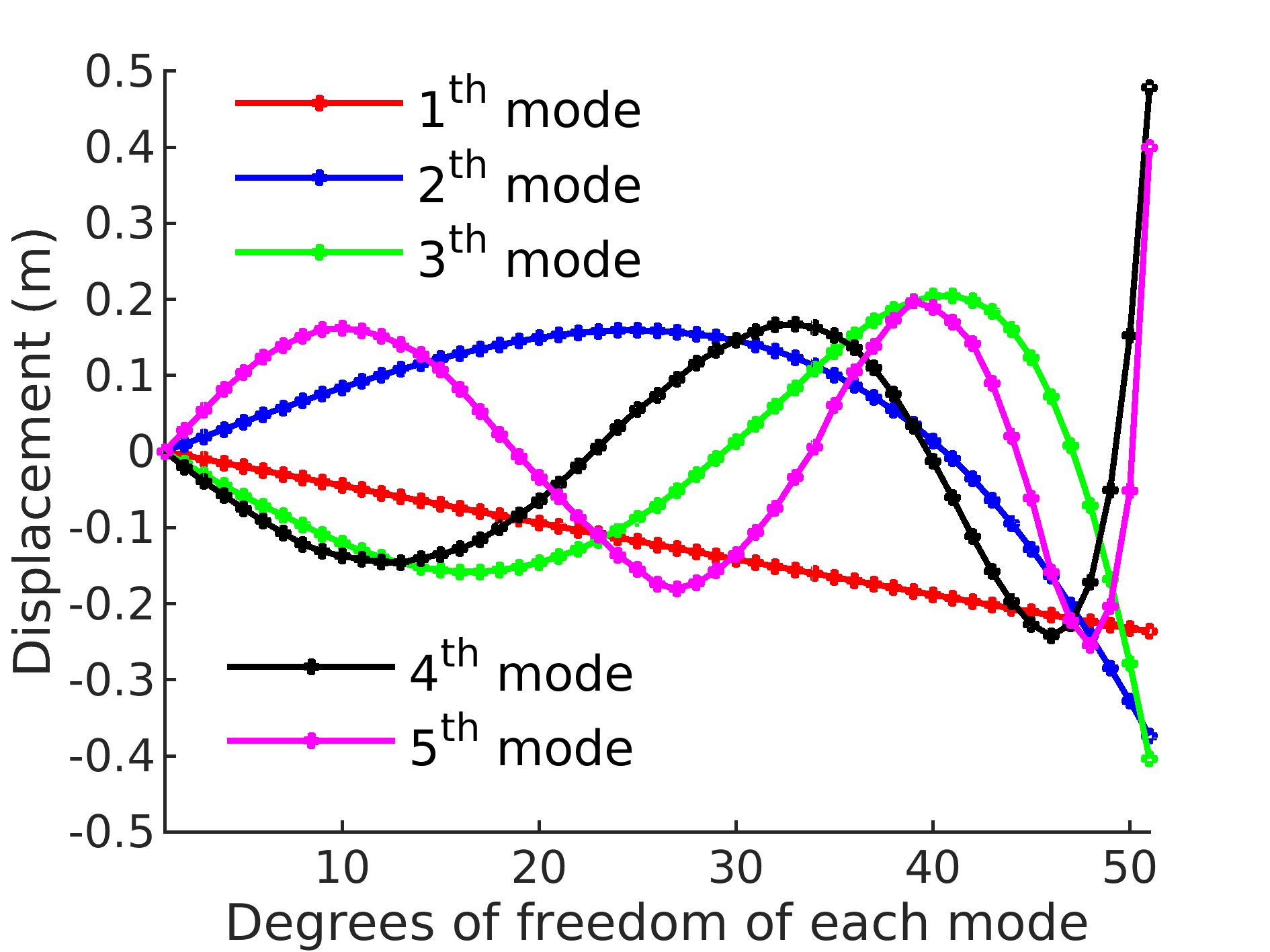
During the simulation, the positions of material points are recorded in matrix (28) in which the number of spatial intervals of sampling points . After that, the recorded data was decomposed with (31) to obtain the dynamic modes of the cable. The first five modes of the cable are illustrated in Figure 3 for the data gathered through the aforementioned simulation.
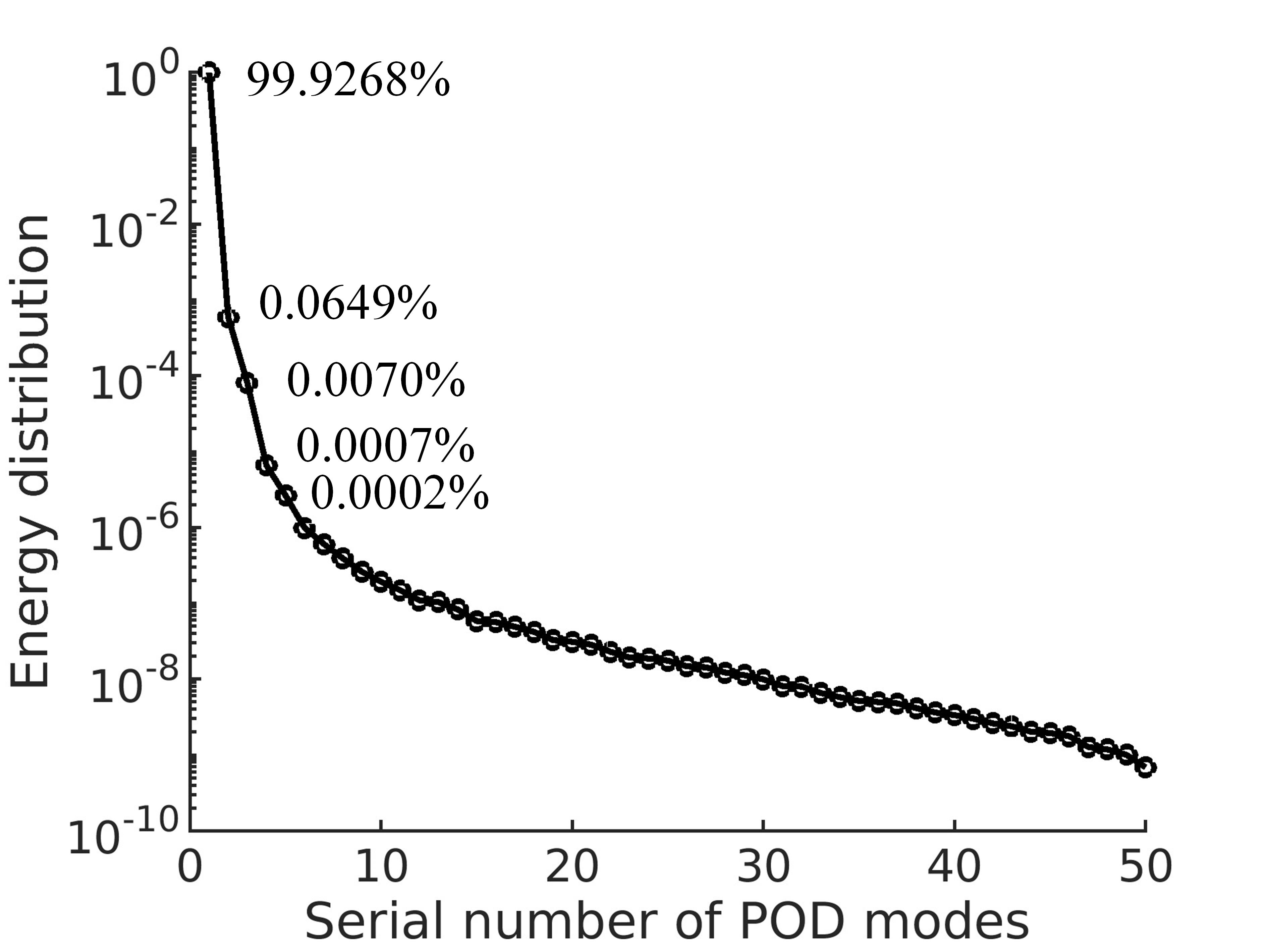
According to (33), the energy distribution of each POD mode to the total energy is shown in Figure 4. It can be found the first POD mode has the major energy. And, the energy distribution of the first three modes is more than . Hence, for simplification, only the first modes are considered for model order reduction in the following numerical validation.
V-B Performance of the Reduced-Order Model
To verify the performance of the ROM derived in Section III, two numerical simulations are executed: one uses FDM to compute the cable dynamics ((16)-(20)), and the other uses the ROM model ((36)-(41)). For decreasing the complexity of ROM (used in trajectory planning and NMPC procedures), the number of sampling points on the cable which is computed by FDM is set as . The initial conditions and boundary conditions of these two simulations are set equal to each other. The initial configuration of the cable is set equal to (the cable lies horizontally), and the initial velocity of each material point on the cable is put to zero. Hence, for FDM, the initial state of the cable is expressed as :
| (50) |
For the ROM, the cable’s initial state is given in (51):
| (51) |
The cable’s boundary condition is preset as in (52):
| (52) |
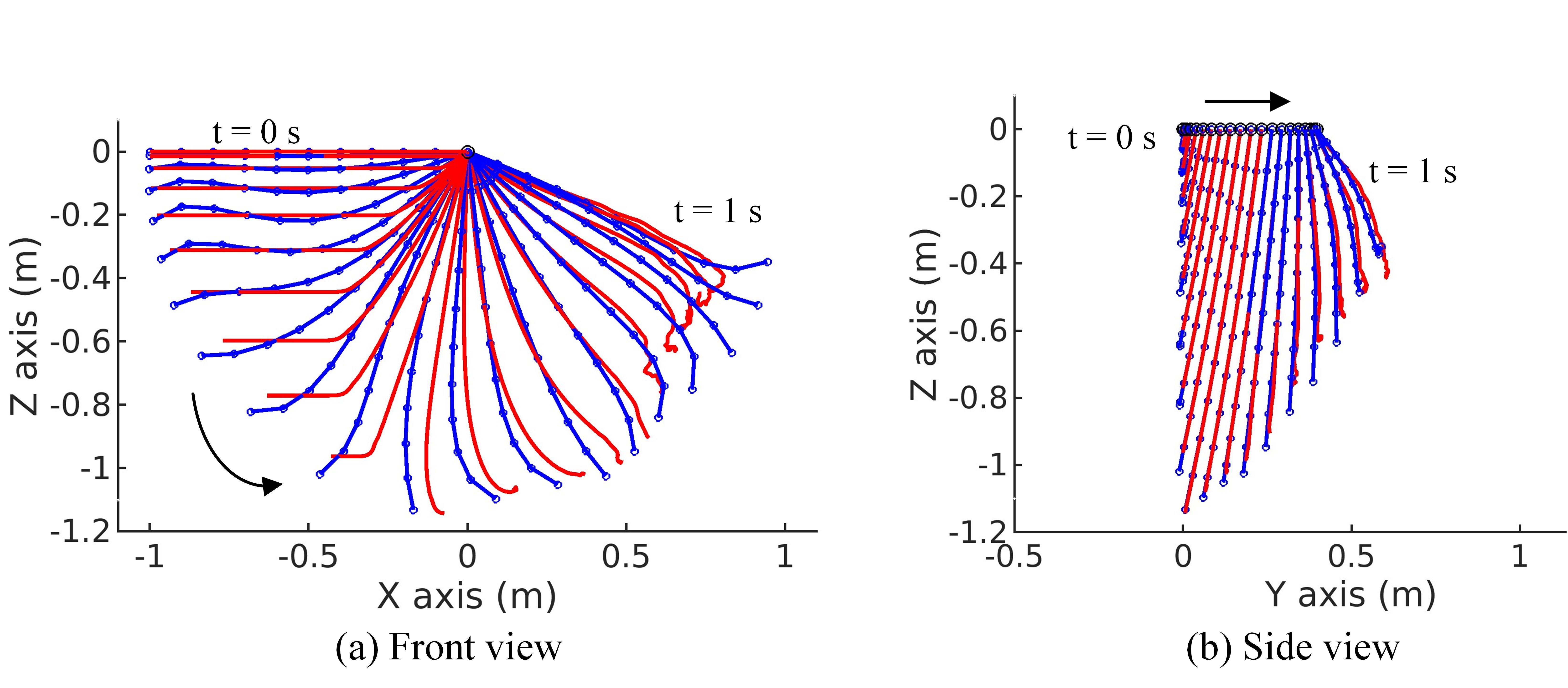
Figure 5 illustrates the snapshots of the configuration of the cable obtained with the two different models during simulation time . From Figure 5, it can be appreciated how the ROM can approximately describe the deformation and motion of the cable governed by PDEs.
For quantifying the difference between the two models, two time-dependent errors expressed in (53) and (54) are established to measure the shape difference and its rate of change, respectively.
| (53) |
| (54) |
in which, and are the position and velocity vector of the node on the FDM model at time , respectively; and are the position and velocity vector of the node on the ROM model respectively.
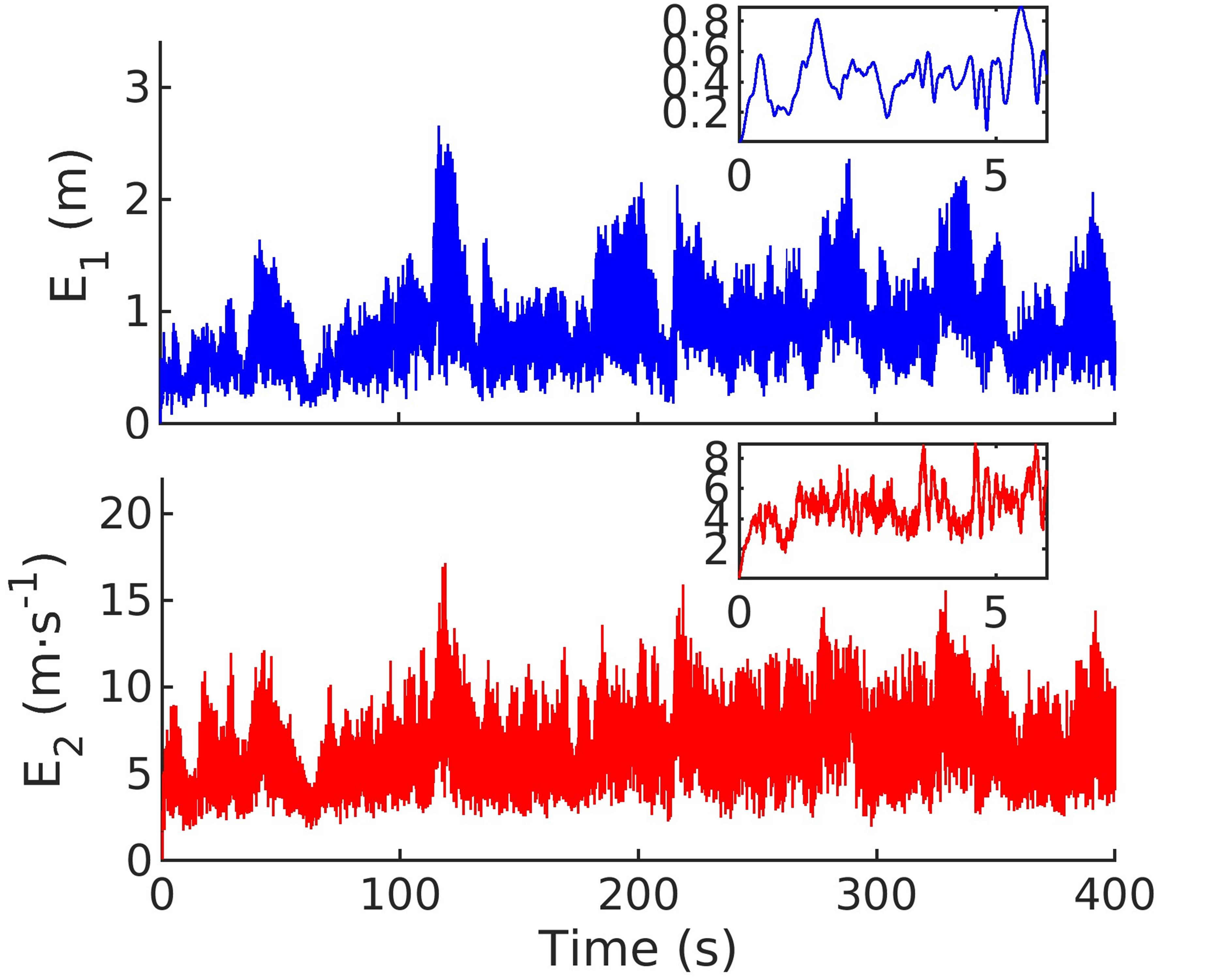
Figure 6 shows the evolution of two indicators during simulation time . In the zoomed portion on the top right, it can be seen that the shape error and shape change rate error between the two models increase gradually in the first six seconds. After that, the errors remain more or less constant for the following 400 seconds. It can also be noted that the errors exhibit vibrations; those are mainly caused by the phase difference of the cable swing motion.
Figure 5 and Figure 6 suggest that, in a short time (less than ), the ROM model could approximately describe the deformation and motion of the original PDM model (under the same initial and boundary conditions). With time, the models’ differences increase and the correspondence between the two models is gradually lost.
V-C Regulation problem
In this subsection, we show a simulated scenario in which the quadrotor-cable system is expected to reach and maintain the static equilibrium point starting from an initial state that is away from the equilibrium state itself.
To highlight the added value of the proposed control architecture, this task is executed both with the geometric PID controller [37] and the proposed NMPC. The previous geometric PID controller only considers the state of the quadrotor, which forces the quadrotor to converge to a certain state or track a desired trajectory, while the forces applied on the quadrotor by the cable are regarded as external disturbances. Instead, the proposed NMPC, shown in Figure 2, considers both the states of the quadrotor and that of the flexible cable.
In this scenario, the initial state of the cable is set as in (50), and the initial attitude state of the quadrotor is set as: . The gains of the attitude controller of both NMPC and PID controller are set as , and . Additionally, the weight matrices in (43) are chosen as , . The values of the weight matrix are chosen intuitively, in a way that emphasizes the importance given to the first mode of the cable.
The equilibrium point of the cable is represented by
| (55) |
which is obtained by solving the differential equation (12) substituting the equilibrium conditions , and the boundary condition .
By using (42), the equilibrium state of the cable is transformed to the reference state of the cable’s ROM . In this test, the reference position of the cable upper endpoint is set to .
In order to obtain best proportional gains and derivative gains of the PID controller for the translational motion of the quadrotor, the values of diagonal elements of and are searched in the domain of to get the minimum value of the following metric
| (56) |
where, is the simulation time, is the control step time and is the cable state in ROM sampled at control step.
Differential gradient descent method was implemented to find the best control gains and which minimizes the value of the metric , and the initial guess of this optimization problem is set as , . After searching, the gains of the PID controller for the translational errors are chosen as , , while the corresponding minimum metric found is .
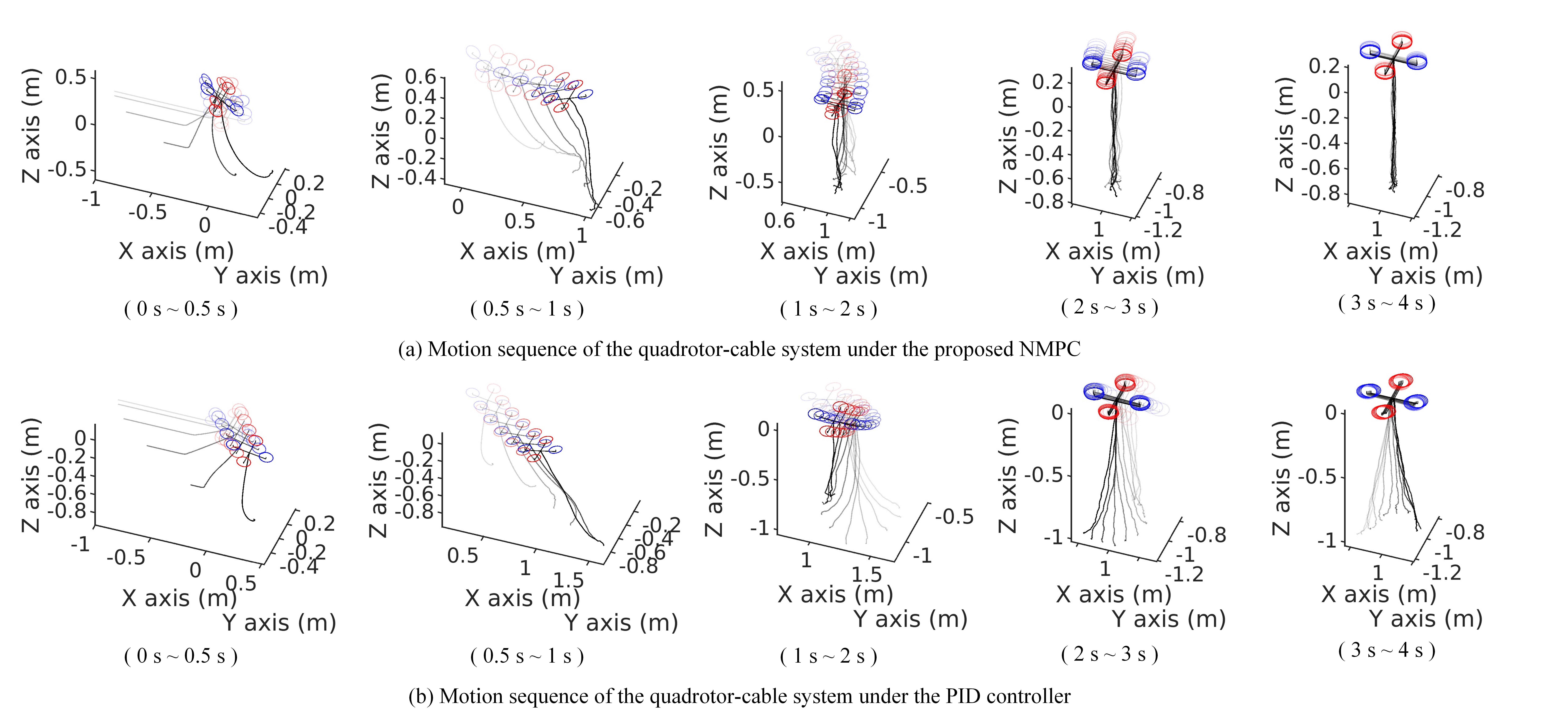
Figure 7 illustrates the two motion sequences of the quadrotor-cable system controlled by the proposed NMPC (Figure 7(a)) and the PID (Figure 7 (b)). In Figure 7(a), after the cable is released from the initial horizontal configuration, the quadrotor tilts to generate translational motion to suppress the swing motion of the cable. It requires for the quadrotor to approximately suppress the swing of the cable and bring the cable to the target equilibrium as in (55). Instead, in Figure 7(b), the PID-controlled quadrotor moves to reach its target position failing to effectively suppress the cable oscillations.


Figures 8 and 9 show the evolution of coefficients of the cable’s dominating POD modes and the position of the cable endpoint with the proposed NMPC and with PID controller, respectively. From Figure 8(a) and 8(d), we see that the first-order mode and upper endpoint position of the cable converge to the corresponding target state. Inspecting Figure 9, we see that the PID controller fails to suppress the first-order mode vibrations and stabilize the cable’s upper endpoint even after double the time required for the NMPC. Additionally, comparing 8(b) and 8(c) with 9(b) and 9(c), it is found that the residual vibration amplitudes of the second-order and third-order modes under PID controller are larger, which shows the suppressing ability of NMPC in the three dominating modes of the cable.
V-D Shape Trajectory Tracking
In the second scenario, the quadrotor is required to let the cable track a certain shape trajectory, which includes both the motion and the shape deformation of the cable. In this subsection, the cable’s shape trajectory generation method is first introduced based on the ROM of the cable. After that, the proposed NMPC and PID controller are implemented on the quadrotor-cable system to let the cable track the desired shape trajectory defined in the cable ROM, respectively. The PID controller used in this section is the same as the previous regulation problem section, it only considers the state of the quadrotor and forces the quadrotor to track the desired trajectory which is generated by the ROM. Additionally, external disturbances affecting the quadrotor are also considered in this cable shaped trajectory tracking scenario. Finally, uncertainties of different parameters of the cable are induced in numerical experiments to show the effects of each parameter uncertainty on the robustness of the proposed control method.
The initial state of the system in the second scenario is set as follows: the initial configuration of the cable is set as , and the velocity of each material point on the cable is set as zero. The initial attitudinal state of the quadrotor is set as . The weight matrices of the NMPC, and are set as the same as the regulation scenario, and the gains of the PID controller are also set as the same as the previous scenario.
The dynamically feasible reference trajectory for the cable in the ROM space is generated by recording the evolution of the cable in a preliminary simulation where the upper endpoint tracks a cycle trajectory expressed on the horizontal plane as
| (57) |
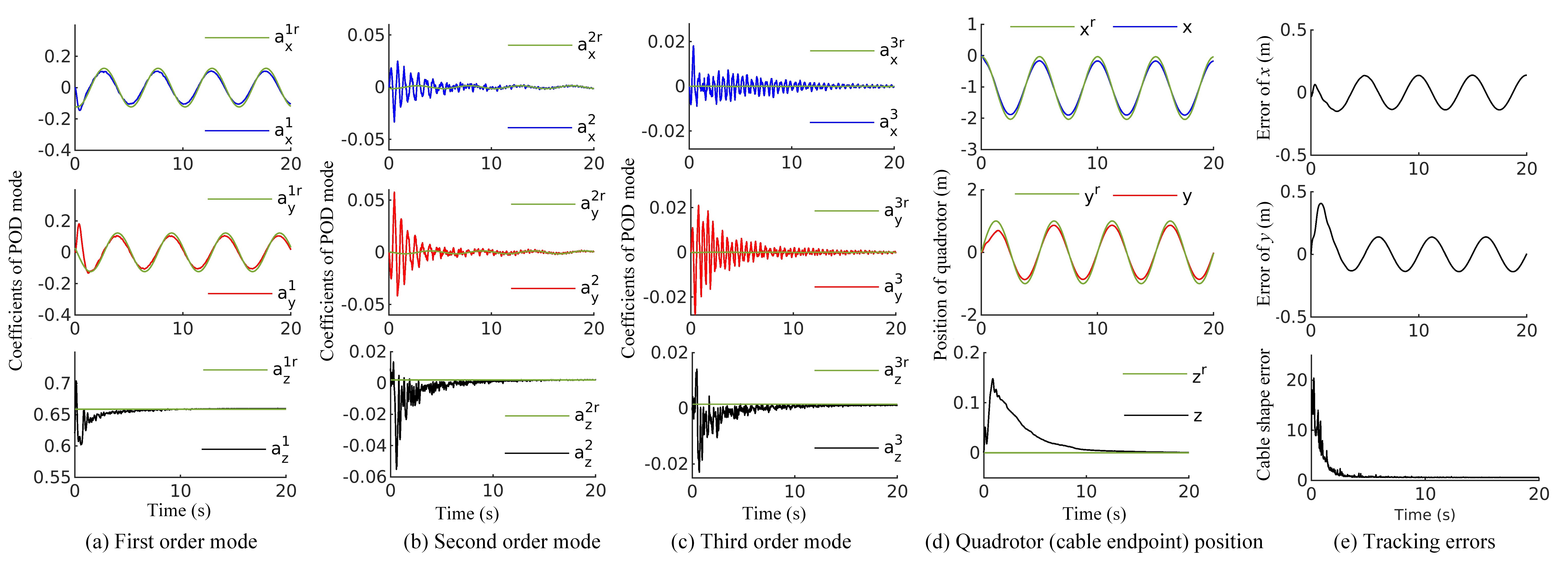
After taking the first and second derivatives of (57), the velocity and acceleration of the upper endpoint are obtained. The evolution of the coefficients of dominating modes of the cable is numerically solved with special control inputs and the initial state of the cable ROM, calculated from (42) with the initial configuration of the cable. During this preliminary simulation, the state of the cable converges to a limit cycle whose period is the same as the period of the circular motion of the cable’s upper endpoint. Hence, this periodic state trajectory of the ROM is trimmed as the cable’s reference shape trajectory shown in the dash lines in Figure 10 and also green lines in Figures 11 and 12.

Figures 10(a) and 10(b) illustrate the motion sequences of the quadrotor-cable system in the cable shape-tracking scenario, while the proposed NMPC and PID controller is implemented, respectively. Comparing the two figures, it is found that with the proposed NMPC, the quadrotor could carry the cable in a neighborhood of the desired state in less time. Conversely, with the PID controller, the cable swings considerably in the first part of the execution, and the cable configuration remains far from the desired one.
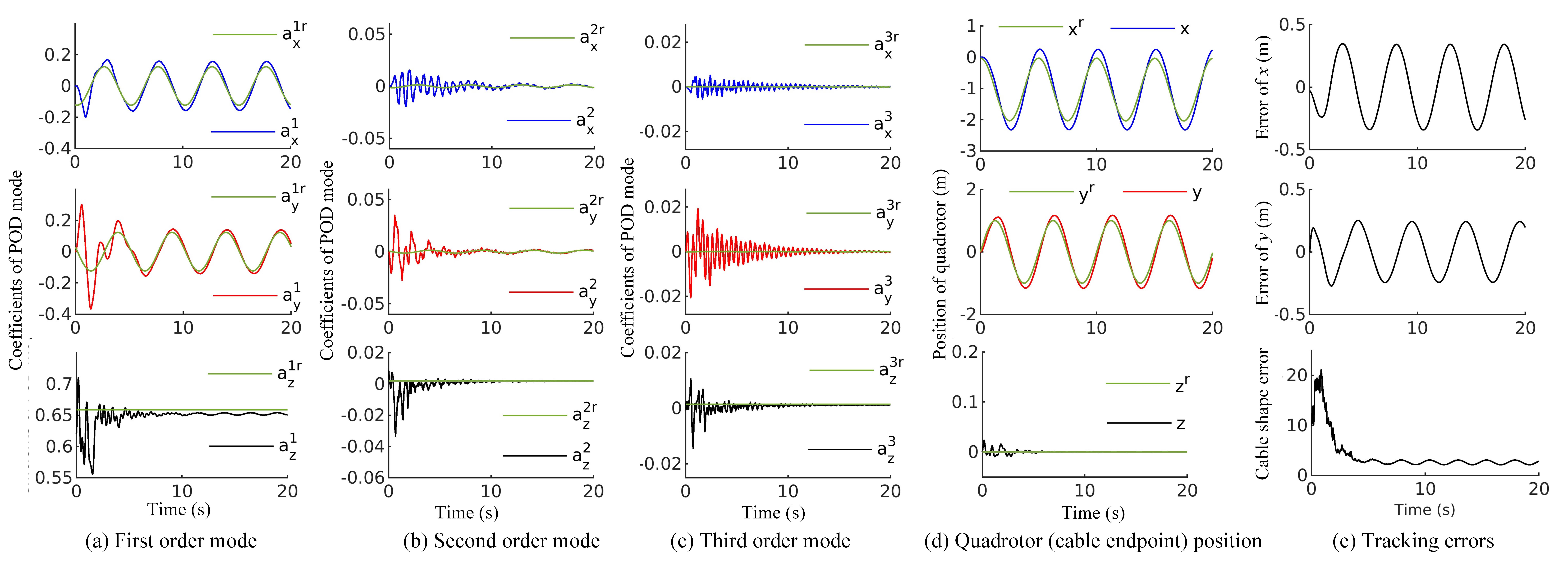
Figures 11 and 12 illustrate the trajectory tracking performance with the proposed NMPC and PID controller, respectively. From Figure 11, one can see that the coefficients of each POD mode and the position of the cable’s upper point converge to the reference trajectory, showing the shape-trajectory-tracking ability of the proposed NMPC. Figure 11(e) shows the tracking errors of the quadrotor for the periodic references in and directions, and the total cable shape error computed as
| (58) |
where the reference state is indicated as and the actual one is . In (58), the weight matrix is the same as previously defined.
Comparing the results in Figures 11 with those in Figures 12, it is found that the PID controller requires more time to let the first-order mode coefficients converge, and it shows less accuracy in their tracking. In addition, Figure 11(e) and 12(e) show that the PID controller performs worse than NMPC in the quadrotor tracking and it gives a higher overall shape-tracking error of the cable at convergence. From 12(d), a non-negligible phase delay can be noticed between reference trajectory and actual state in and direction with PID controller.
V-D1 External disturbances
In this section, the performances of the two controllers are tested under disturbance conditions. It is assumed that the quadrotor suffers external translational forces during the same task execution as in the first part of Section V-D. Hence, the boundary conditions of the cable (translational dynamics of the quadrotor) in (13) are replaced by:
| (59) |
where is the external disturbance force along three axes of the world frame. The three coordinates of are assumed to be random square wave signals whose amplitude is bounded in the set and their frequency set as 0.5 Hz.
Figures 10(c) and 10(d) illustrate the trajectory tracking motion sequences of the quadrotor-cable system affected by external disturbance, while the proposed NMPC and PID controller are implemented, respectively. In both cases, the random square wave signals are the same. Comparing Figures 10(c) and 10(d), it can be seen that the cable shape tracking performance with the proposed NMPC is better than with the PID controller. Indeed, when the PID is used, the cable undergoes a clear swinging motion due to unsuppressed external disturbances.
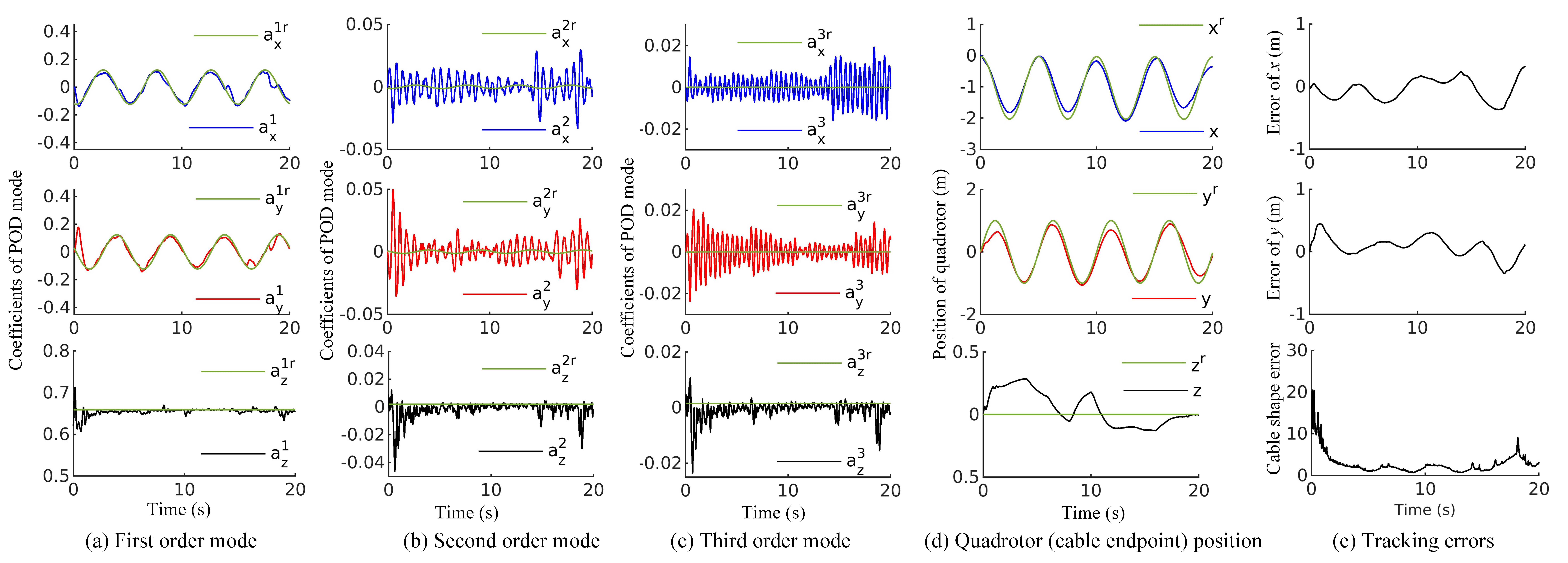
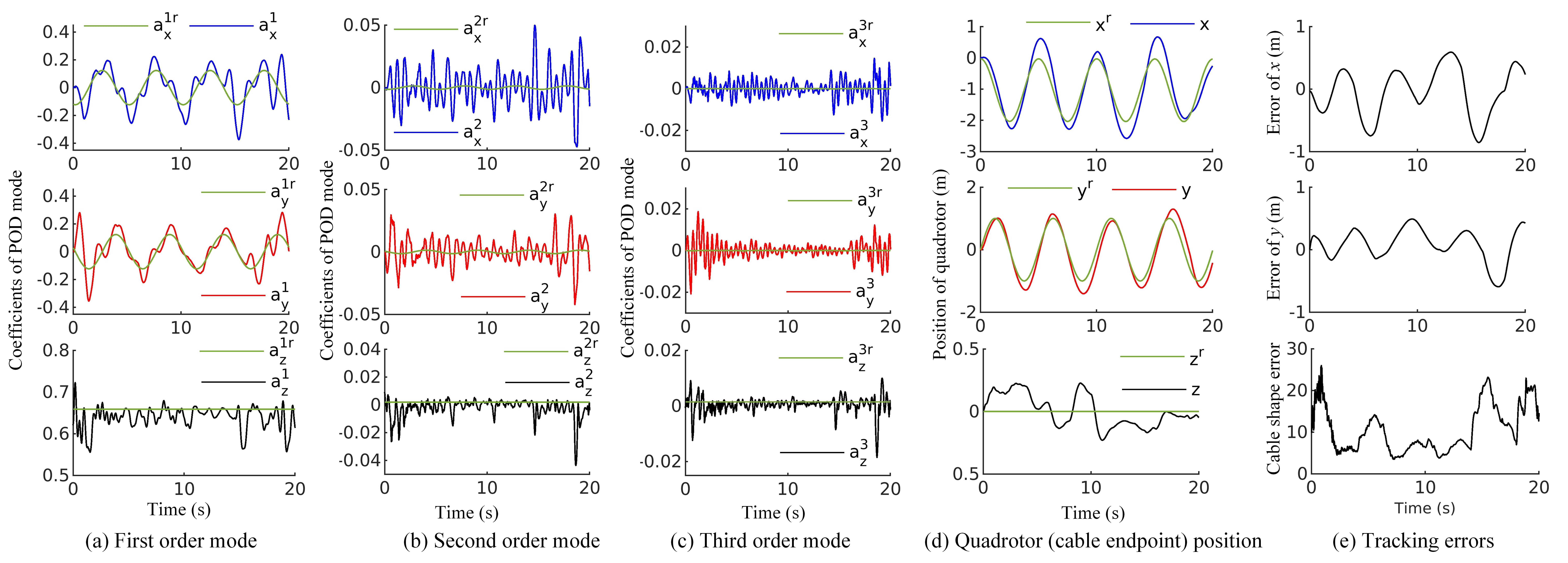
The results of the task execution under disturbances are reported in Figure 13 and 14 for the proposed NMPC and the PID controller, respectively. From Figures 13(a) and Figure 13(d), one can see that the coefficients of the first POD mode and the position of the quadrotor could follow their corresponding references quite well. In Figures 13(b) and figures 13(c), the coefficients of the cable’s second- and third-order mode remain in the neighborhood of the desired reference.
Comparing the results in Figures 13 with those in Figures 14, the tracking performance obtained with the PID controller emerges to be especially worse in the first-order mode than with the proposed NMPC. The errors in the tracking of the quadrotor position and the overall cable shape are also higher in the former case. These tests show that with the proposed NMPC, the quadrotor could carry the cable to track the reference shape and also the trajectory and translational trajectory of the quadrotor itself.
V-D2 Model parameter uncertainty
In this section, the effects of different model parameter uncertainties on the cable shape trajectory tracking performance are also analyzed. To do so, we use the metric as in (60) to evaluate the cable shape tracking error, where and are the duration of the simulation and control time step, respectively; and is the reference state and actual state of the cable in ROM sampled at control step.
| (60) |

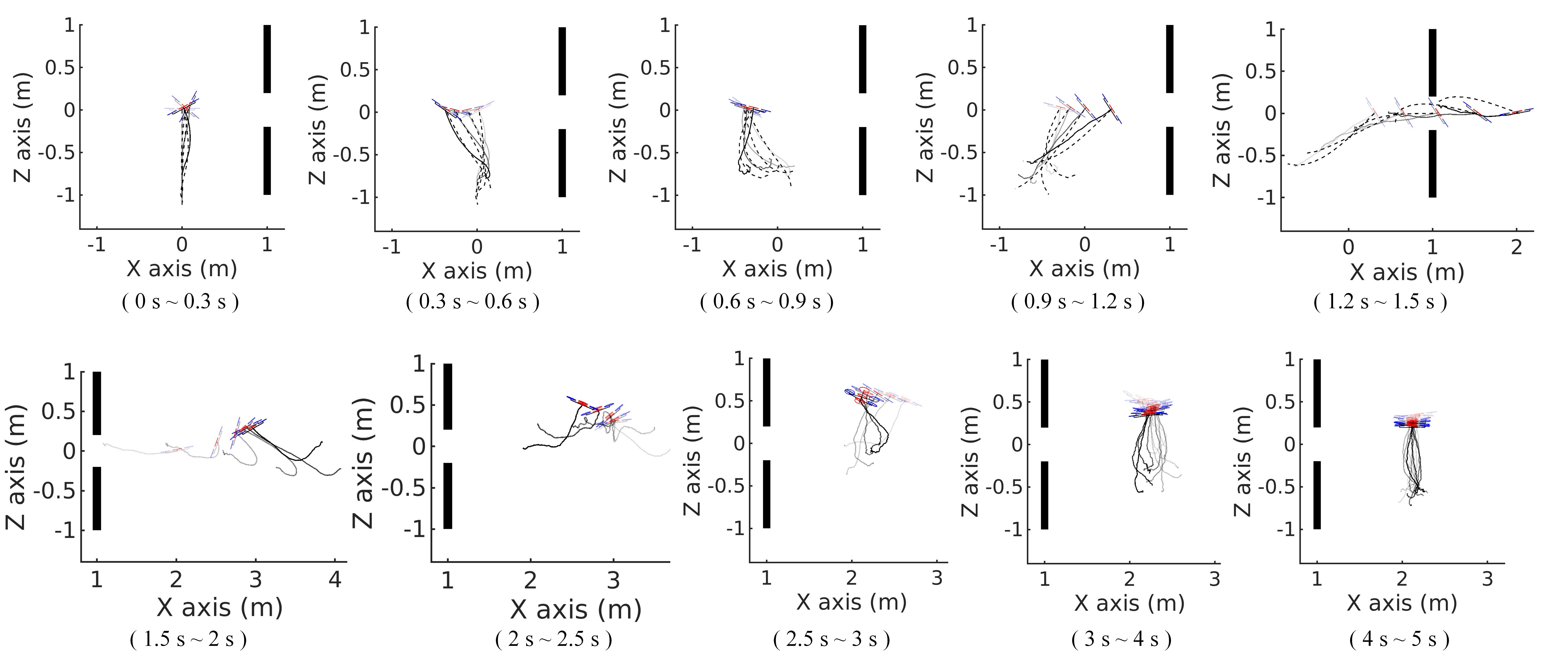
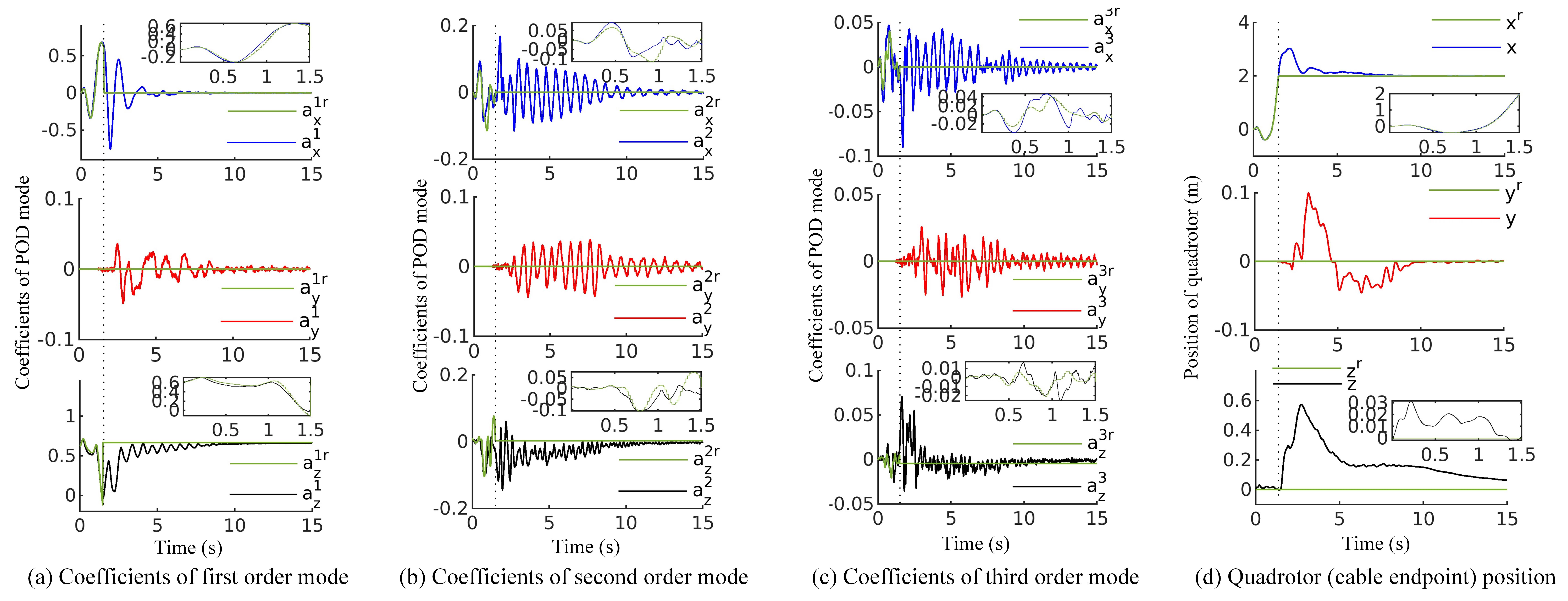
Figure 15 shows the tracking errors with different uncertainties on different parameters: the cable’s aerial drag coefficient , its Young modulus , density , and length . We found that the effects of a positive or a negative uncertainty on or are asymmetric. Especially, when the real value of the aerodynamic coefficient is greater than the known one, , the tracking error increases sharply. On the contrary, if is lower than , the tracking error remains almost stationary. Interestingly, an actual drag coefficient lower than the one used by the controller seems to be negligible for the task execution. For the Young modulus, the situation is reversed: if the is higher than its nominal value, the tracking error slightly and slowly increases and then maintains a constant value; when decreases, on the other hand, the tracking error sharply increases. This can be intuitively explained: when the Young modulus of the cable is high, the cable will basically not change its length under the effect of the forces involved in the manipulation task. Instead, when is reduced, the cable becomes more and more compliant and elongates under the effect of gravity and other forces, causing an increase in the shape trajectory error.
The effects of uncertainties on the cable density and length are nearly symmetric. When changing the value of and w.r.t. to the value used in the controller, the tracking error increases. Additionally, the tracking error is more sensitive to the uncertainty of cable length: it was found that a error in leads to an error comparable to what results from a error in the cable density.
V-E Narrow Window Crossing
In this scenario, the quadrotor is required to carry the cable through a narrow window, as schematically represented in Figure 16. In the window crossing, the cable and the quadrotor itself should not collide with the boundary of the window area. In this scenario, the window is a vertical square opening wide and its center is placed in the point of the world frame. The collision constraint for the quadrotor and the cable is
| (61) |
and the initial state of the system is the same as in Sec. V-D. The target configuration of the cable is the equilibrium state expressed as (55) where the position of the endpoint is set as .
An offline trajectory planner is designed to generate a feasible shape trajectory for the cable that satisfies the constraint. After that, the proposed NMPC is used for the quadrotor to let the cable track the designed cable shape reference trajectory. Finally, the NMPC is switched to stabilization-control mode, the same as in the first scenario in Sec. V-C, to let the cable converge to the final target equilibrium configuration.
The trajectory planner is implemented as follows. First, only the motion of the cable upper endpoint in the direction is considered. Then, the Fourier series expressed in (62) is used for representing the translational motion of the quadrotor (cable upper endpoint). In (62), are the coefficient of the Fourier series, and is the time duration of the planned trajectory for crossing the narrow window. After that, by taking the first and second derivatives of (62), the velocity and acceleration of the cable endpoint are obtained.
| (62) |
The reference shape trajectory of the cable is obtained by solving the following feasibility problem
| (63) | ||||
where is the first component of (62), is the initial state of the cable, and are the lower and upper boundary of the quadrotor acceleration in the direction, respectively. For this optimization problem (63), the particle swarm optimization (PSO) algorithm [38] was used to find the feasible solution.
Figure 16 illustrates the motion sequence of the quadrotor-cable system passing through the narrow window area. The first five snapshots show the motion of the quadrotor-cable system and also the reference motion of the cable (dashed line) in the cable shape trajectory tracking stage. In this first stage, the control gains of the proposed NMPC are set as (while other gains keep the same as previous section Sec. V-D) to emphasize the translational motion error of the quadrotor. It is found that, with the proposed NMPC, the quadrotor can carry the cable to approximately track the planned reference shape trajectory. After , the NMPC switches to regulation mode (the control gains remain the same as the Sec. V-C), and it requires around to let the cable converge to the target configuration.
Figure 17 illustrates the evolution of the coefficients of each POD mode of the cable and the position of the cable’s upper point. In the first stage, from to , the coefficients of each POD mode of the cable and the position of the cable’s upper point follow their corresponding references, after , the coefficients of each POD mode of the cable and the position of the cable’s upper point converge to their references, which also verifies the cable shape trajectory tracking ability of the proposed controller.
VI Conclusions
In this work, a novel PDE-based mathematical model for the system composed of a quadrotor carrying a flexible cable is presented. Then a Reduced-Order Model (ROM) model exploiting the proper orthogonal decomposition is also proposed for control purposes. Numerical simulation results employing FDM-based discretization of the full PDE-based model show that the Reduced-Order Model (ROM) has the capability to predict the evolution of the system with sufficient accuracy and a much lower number of states. To perform cable shape trajectory tracking, we then proposed a novel NMPC scheme that uses the ROM in its prediction phase.
The proposed controller is numerically tested in actual control challenges simulating the system with the accurate model based on FDM in three different scenarios including regulation, cable shape trajectory tracking, and window crossing. The sensitivity of the control error to parametric variation is also numerically assessed.
In the future, physical experiments will be executed to analyze the predictive capability of the ROM and test the performance of the ROM-based NMPC with a physical system.
References
- [1] I. Maza, K. Kondak, M. Bernard, and A. Ollero, “Multi-uav cooperation and control for load transportation and deployment,” Journal of Intelligent and Robotic Systems, vol. 57, pp. 417–449, 2010.
- [2] D. Villa, A. S. Brandão, and M. Sarcinelli-Filho, “A survey on load transportation using multirotor uavs,” Journal of Intelligent & Robotic Systems, vol. 98, pp. 1–30, 2020.
- [3] A. S. Brandão, D. Smrcka, E. Pairet, T. Nascimento, and M. Saska, “Side-pull maneuver: A novel control strategy for dragging a cable-tethered load of unknown weight using a uav,” IEEE Robotics and Automation Letters, vol. 7, no. 4, pp. 9159–9166, 2022.
- [4] M. Bernard and K. Kondak, “Generic slung load transportation system using small size helicopters,” in 2009 IEEE International Conference on Robotics and Automation, 2009, pp. 3258–3264.
- [5] A. Tagliabue, M. Kamel, S. Verling, R. Siegwart, and J. Nieto, “Collaborative transportation using mavs via passive force control,” in 2017 IEEE International Conference on Robotics and Automation, 2017, pp. 5766–5773.
- [6] K. Ro and J. W. Kamman, “Modeling and simulation of hose-paradrogue aerial refueling systems,” Journal of Guidance, Control, and Dynamics, vol. 33, no. 1, pp. 53–63, 2010.
- [7] Z. Liu, J. Liu, and W. He, “Modeling and vibration control of a flexible aerial refueling hose with variable lengths and input constraint,” Automatica, vol. 77, pp. 302–310, 2017.
- [8] Z. Liu, J. Liang, S. Zhang, and E. Kayacan, “Ann-based vibration control of an aerial refueling hose system with input nonlinearity and prescribed output constraint,” Journal of the Franklin Institute, vol. 359, no. 6, pp. 2627–2645, 2022.
- [9] M. Song and P. Huang, “Dynamics and anti-disturbance control for tethered aircraft system,” Nonlinear Dynamics, vol. 110, no. 3, pp. 2383–2399, 2022.
- [10] A. Ollero, M. Tognon, A. Suarez, D. Lee, and A. Franchi, “Past, present, and future of aerial robotic manipulators,” IEEE Transactions on Robotics, vol. 38, no. 1, pp. 626–645, 2022.
- [11] A. Tagliabue, M. Kamel, R. Siegwart, and J. Nieto, “Robust collaborative object transportation using multiple mavs,” The International Journal of Robotics Research, vol. 38, no. 9, pp. 1020–1044, 2019.
- [12] I. Palunko, R. Fierro, and P. Cruz, “Trajectory generation for swing-free maneuvers of a quadrotor with suspended payload: A dynamic programming approach,” in 2012 IEEE International Conference on Robotics and Automation, 2012, pp. 2691–2697.
- [13] I. H. B. Pizetta, A. S. Brandão, and M. Sarcinelli-Filho, “Modelling and control of a pvtol quadrotor carrying a suspended load,” in 2015 International Conference on Unmanned Aircraft Systems, 2015, pp. 444–450.
- [14] C. Y. Son, H. Seo, T. Kim, and H. Jin Kim, “Model predictive control of a multi-rotor with a suspended load for avoiding obstacles,” in 2018 IEEE International Conference on Robotics and Automation, 2018, pp. 5233–5238.
- [15] C. Y. Son, H. Seo, D. Jang, and H. J. Kim, “Real-time optimal trajectory generation and control of a multi-rotor with a suspended load for obstacle avoidance,” IEEE Robotics and Automation Letters, vol. 5, no. 2, pp. 1915–1922, 2020.
- [16] M. Gassner, T. Cieslewski, and D. Scaramuzza, “Dynamic collaboration without communication: Vision-based cable-suspended load transport with two quadrotors,” in 2017 IEEE International Conference on Robotics and Automation, 2017, pp. 5196–5202.
- [17] G. Li, R. Ge, and G. Loianno, “Cooperative transportation of cable suspended payloads with mavs using monocular vision and inertial sensing,” IEEE Robotics and Automation Letters, vol. 6, no. 3, pp. 5316–5323, 2021.
- [18] G. Li and G. Loianno, “Nonlinear model predictive control for cooperative transportation and manipulation of cable suspended payloads with multiple quadrotors,” in 2023 IEEE/RSJ International Conference on Intelligent Robots and Systems, 2023, pp. 5034–5041.
- [19] K. Sreenath, T. Lee, and V. Kumar, “Geometric control and differential flatness of a quadrotor uav with a cable-suspended load,” in 52nd IEEE Conference on Decision and Control, 2013, pp. 2269–2274.
- [20] S. Tang and V. Kumar, “Mixed integer quadratic program trajectory generation for a quadrotor with a cable-suspended payload,” in 2015 IEEE International Conference on Robotics and Automation, 2015, pp. 2216–2222.
- [21] P. Kotaru, G. Wu, and K. Sreenath, “Dynamics and control of a quadrotor with a payload suspended through an elastic cable,” in 2017 American Control Conference, 2017, pp. 3906–3913.
- [22] P. Foehn, D. Falanga, N. Kuppuswamy, R. Tedrake, and D. Scaramuzza, “Fast trajectory optimization for agile quadrotor maneuvers with a cable-suspended payload,” in 2017 Robotics: Science and Systems (RSS), 2017.
- [23] J. Goodman and L. Colombo, “Geometric control of two quadrotors carrying a rigid rod with elastic cables,” Journal of Nonlinear Science, vol. 32, no. 5, p. 65, 2022.
- [24] J. R. Goodman, T. Beckers, and L. J. Colombo, “Geometric control for load transportation with quadrotor uavs by elastic cables,” IEEE Transactions on Control Systems Technology, vol. 31, no. 6, pp. 2848–2862, 2023.
- [25] M. Tognon, C. Gabellieri, L. Pallottino, and A. Franchi, “Aerial co-manipulation with cables: The role of internal force for equilibria, stability, and passivity,” IEEE Robotics and Automation Letters, vol. 3, no. 3, pp. 2577–2583, 2018.
- [26] C. Gabellieri, M. Tognon, D. Sanalitro, L. Pallottino, and A. Franchi, “A study on force-based collaboration in swarms,” Swarm Intelligence, vol. 14, no. 1, pp. 57–82, 2020.
- [27] C. Gabellieri, M. Tognon, D. Sanalitro, and A. Franchi, “Equilibria, stability, and sensitivity for the aerial suspended beam robotic system subject to parameter uncertainty,” IEEE Transactions on Robotics, vol. 39, no. 5, pp. 3977–3993, 2023.
- [28] F. A. Goodarzi, D. Lee, and T. Lee, “Geometric control of a quadrotor uav transporting a payload connected via flexible cable,” International Journal of Control, Automation and Systems, vol. 13, no. 6, pp. 1486–1498, 2015.
- [29] P. Kotaru, G. Wu, and K. Sreenath, “Differential-flatness and control of quadrotor(s) with a payload suspended through flexible cable(s),” in 2018 Indian Control Conference (ICC), 2018, pp. 352–357.
- [30] P. Kotaru and K. Sreenath, “Multiple quadrotors carrying a flexible hose: dynamics, differential flatness and control,” IFAC-PapersOnLine, vol. 53, no. 2, pp. 8832–8839, 2020.
- [31] J. Quisenberry and A. Arena, “Discrete cable modeling and dynamic analysis,” in 44th AIAA Aerospace Sciences Meeting and Exhibit, 2006.
- [32] C. Gabellieri and A. Franchi, “Differential flatness and manipulation of elasto-flexible cables carried by aerial robots in a possibly viscous environment,” in 2023 International Conference on Unmanned Aircraft Systems, 2023, pp. 963–968.
- [33] S. Antman, Nonlinear Problems of Elasticity; 2nd ed. New York: Springer, 2005.
- [34] M. Hamandi, F. Usai, Q. Sablé, N. Staub, M. Tognon, and A. Franchi, “Design of multirotor aerial vehicles: A taxonomy based on input allocation,” The International Journal of Robotics Research, vol. 40, no. 8-9, pp. 1015–1044, 2021.
- [35] K. Taira, S. L. Brunton, S. T. Dawson, C. W. Rowley, T. Colonius, B. J. McKeon, O. T. Schmidt, S. Gordeyev, V. Theofilis, and L. S. Ukeiley, “Modal analysis of fluid flows: An overview,” AIAA journal, vol. 55, no. 12, pp. 4013–4041, 2017.
- [36] K. Taira, M. S. Hemati, S. L. Brunton, Y. Sun, K. Duraisamy, S. Bagheri, S. T. Dawson, and C.-A. Yeh, “Modal analysis of fluid flows: Applications and outlook,” AIAA journal, vol. 58, no. 3, pp. 998–1022, 2020.
- [37] F. Kendoul, Z. Yu, and K. Nonami, “Guidance and nonlinear control system for autonomous flight of minirotorcraft unmanned aerial vehicles,” Journal of Field Robotics, vol. 27, no. 3, pp. 311–334, 2010.
- [38] J. Kennedy and R. Eberhart, “Particle swarm optimization,” in Proceedings of ICNN’95 - International Conference on Neural Networks, vol. 4, 1995, pp. 1942–1948.