NewThe other list ††thanks: Corresponding author: vedangi@phas.ubc.ca.
Edge currents as probe of topology in twisted cuprate bilayers
Abstract
Bilayers made of high- cuprate superconductor Bi2Sr2CaCu2O8+x assembled with a twist angle close to have been recently shown to spontaneously break time reversal symmetry , consistent with theoretical predictions for emergent chiral topological phase in such twisted -wave superconductors. Here we use a minimal microscopic model to estimate the size of spontaneous chiral edge currents expected to occur in the -broken phase. In accord with previous theoretical studies of chiral -wave superconductors we find small but non-vanishing edge currents which we nevertheless predict to be above the detection threshold of the state-of-the-art magnetic scanning probe microscopy. In addition, by deriving a simple relation between the edge current and the electron spectral function we help elucidate the longstanding disparity between the size of edge currents in chiral -wave and -wave superconductors.
I Introduction
Chiral superconductors are characterized by the order parameter with integer being both the magnetic quantum number which determines the orbital angular momentum (OAM) per Cooper pair and the Chern number which is a topological invariant characterizing the Bogoliubov-de Gennes (BdG) spectrum and determining number of the chiral edge modes [1, 2, 3]. Such an order parameter breaks time reversal symmetry allowing spontaneous currents which we expect to find at the edges of the sample. The edge modes can support the supercurrent, although some states extend into the bulk may also participate [1]. Unlike the Chern insulator, the edge currents in chiral superconductors are not quantized [4]. The reason is that these states are mixtures of particle and hole degrees of freedom and how much electrical current they carry does not only depend on the dispersion but also on the particle-hole content of the wavefunctions. Therefore we might not find current where we expect due to cancellations between particle and hole degrees of freedom [2]. The edge modes give rise to quantized thermal conductance which is, however, notoriously difficult to measure.
Edge currents predicted for a chiral -wave superconductor () within the quasi-classical approximation using a continuum model [1] are consistent with OAM for fermions for a disk geometry. This quasi-classical analysis was generalized in Ref. [2] to higher angular momentum pairing channels () and it was found that edge currents vanish for single band continuum models. This is so even though in the strong coupling (BEC) limit the expected OAM is ; vanishing edge currents in the simplest model suggests that this is not the case.
Edge currents for higher chirality states have not received as much attention as the chiral -wave state (long thought relevant to a candidate triplet superconductor Sr2RuO4), owing chiefly to the paucity of realistic candidate systems. Nevertheless theoretical studies of more complex models [5, 6, 7, 2, 8] have found non-vanishing edge currents in the chiral -wave state. In contrast to the quasi-classical result for single-band continuum theory, Ref. [2] found nonzero edge currents for the case based on self-consistent BdG lattice models of chiral -wave state. Ref. [8] studied edge currents in a disk geometry with size comparable to coherence length, solving quasiclassical Eilenberger equations as well as Maxwell’s equations self-consistently, therefore taking screening effects into account and found that screening does not change the qualitative behavior. Both of these studies however concluded that the chiral -wave has edge currents an order of magnitude smaller than what is expected for chiral -wave.
Here we consider a specific candidate for the chiral -wave superconducting state realized in the 2D heterostructure of twisted bilayer cuprates such as Bi2Sr2CaCu2O8+x (Bi-2212). Composed of two monolayer -wave superconductors (SC) stacked with a near twist such a structure is predicted to host a topological state (abbreviated henceforth as ) with bulk gap and chiral edge modes [9]. Spontaneous -breaking here occurs due to the symmetry-imposed vanishing of the first harmonic in the Josephson energy between the two layers at twist, with the second harmonic favoring the phase difference. Recent transport experiments on twisted Bi-2212 flakes indeed reported fractional Shapiro steps and Fraunhofer patterns consistent with strong second harmonic Josephson energy [10]. The same study also observed a pronounced zero-field superconducting diode effect in near- twisted samples, indicating spontaneous -breaking at the interface [11]. Other transport experiments, however, reported only conventional behavior in twisted Bi-2212 junctions [12] and more recently also in twisted Bi2Sr2CaCuO6+x (Bi-2201) [13]. The most recent transport study of twisted Bi-2212 junctions reported [14], once again, an unconventional behavior consistent with theoretical predictions for twisted -wave superconductors.
On the theory side, more detailed microscopic studies of twisted cuprate bilayers that incorporate the effect of strong correlations [15, 16, 17, 18, 19, 20], inhomogeneity [21, 22] and the effect of applied current and magnetic field [23] make predictions for the -broken phase that differ in important details such as the critical twist angle and the size of the induced excitation gap. Given this situation it is important to explore the full range of physical manifestations of the predicted chiral phase. In addition to the fractional Shapiro steps, Fraunhofer patterns and the diode effect mentioned above signatures of -breaking can be probed directly via polar Kerr effect measurements as proposed in Ref. [24]. Fractional and coreless vortices have been predicted to occur in the chiral SC [25], which could be experimentally detected.
Perhaps the most persuasive direct manifestation of the chiral state, however, would be observation of the spontaneous edge currents associated with the topologically protected edge modes. The aim of this work is to evaluate the edge currents resulting from the spontaneous breaking in a lattice model of a superconducting system designed to capture the physics of twisted Bi-2212 bilayer. To this end we first construct a suitable ‘aligned lattice model’ and solve the resulting Bogoliubov - de Gennes (BdG) theory self-consistently in the long-strip geometry with several types of edges and domain walls that produce spontaneous currents. Based on this solution we calculate the edge currents and the resulting magnetic fields which we find to be strong enough to be detectable with a high-resolution scanning SQUID microscope. As appropriate for a 2D sample of a strongly type-II cuprate superconductor our treatment throughout the paper ignores the Meissner screening.
It is important to note that for a pure, single-layer SC, a different broken state has been predicted to occur near a pair-breaking boundary, e.g. one formed by a (110) edge in a superconductor [26, 27, 28, 29]. In such a state fractional vortex anti-vortex pairs are predicted to spontaneously nucleate along the boundary below , breaking also the translation symmetry along the edge. In our self-consistent treatment of a single-layer superconductor with a (110) edge, we were able to confirm the onset of this broken phase below . Nevertheless this effect remains experimentally unconfirmed [8] and we defer a study of its interplay with the bulk broken phase to future work.
In the remainder of this paper we focus on types of edges and domain walls that are not pair-breaking in the above sense and thus allow us to study edge currents intrinsic to the bulk -broken chiral phase that emerges in the bilayer near a twist. In addition, we focus on bilayer solutions that retain translation invariance along all edges.
II Modelling the twisted bilayer
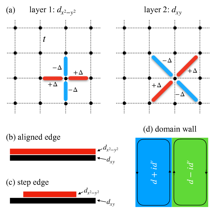
The bulk behavior of a twisted cuprate bilayer is most conveniently described by a continuum BCS theory which has been extensively checked against microscopic lattice models with the correct Fermi surface structure [9, 24, 30]. Because we wish to model behavior of the twisted bilayer near an edge it is preferable to use a lattice model. However, simulating the full microscopic lattice model near the twist tends to be computationally expensive owing to its large moiré unit cell. To avoid complications arising from such a large unit cell we employ here the ‘aligned lattice’ model introduced in Ref. [24]. The idea is to represent two monolayers by two perfectly aligned square lattices. The twist is then implemented by imposing a order parameter in one layer and a order parameter in the other, as illustrated in Fig. 1(a).
II.1 The aligned lattice model
The Hamiltonian of the aligned lattice model is given by with
| (1) | ||||
describing the normal-state tight-binding band structure of the bilayer. Here creates an electron on site with spin in layer , denotes summation over nearest neighbor sites and is the number operator. and denote respectively the in-plane and interplane tunneling amplitudes and is the chemical potential.
describes attractive electron-electron interactions that give rise to -wave superconductivity in the individual layers,
| (2) |
where denotes summation over second-neighbor sites on the square lattice. For positive (and assuming decoupled layers) this form of interaction is known to produce a order in layer 1 and order in layer 2.
Performing the standard mean-field decoupling of the interaction term (2) in the pairing channel one obtains the BdG Hamiltonian. For a uniform system with periodic boundary conditions, it can be written compactly in the momentum space as where and
| (3) |
The normal state for each monolayer has a dispersion . The superconducting order parameters assume the form
| (4) |
and their amplitudes are determined self-consistently from the gap equation,
| (5) |
where is the inverse temperature, are eigenstates of belonging to positive eigenvalues , and the second line is convenient in numerical computations.
We find that for decoupled monolayers a SC with non-zero order parameters defined in Eq. (II.1) represents a stable ground state of the BdG theory for much of the phase diagram spanned by parameters , and . However, a state with extended -wave order parameters defined as
| (6) |
is a close competitor. Here are given by equations analogous to Eqs. (II.1). As discussed in more detail below this competing -wave state tends to crop up in situations where the dominant -wave order parameter is spatially varying, e.g. near the edges.
II.2 Model parameters
We set our normal state parameters as eV, and the interaction strengths as eV, eV. These parameters give us a near-circular Fermi surface, a -wave superconducting order parameter and a maximal gap of approximately 40 meV in each monolayer, in accord with the observed gap size in optimally doped Bi-2212. In addition, critical temperatures in the two monolayers coincide for this parameter choice. We use these parameters for all subsequent calculations except where noted otherwise.
Upon weakly coupling the layers using meV, a self-consistent solution develops a relative phase of between the superconducting order parameters, thereby reproducing the expected order parameter in the twisted bilayer system. Our chosen value of the interlayer coupling follows from the estimate for twisted Bi-2212 bilayers given in Ref. [30] based on experimental data of Ref. [10]. It is to be noted, however, that estimates of vary widely in the available literature. Also, we find that the edge current is quite sensitive to the value of , with larger values generally supporting stronger currents. For this reason we shall give results for edge currents and the associated magnetic fields for several representative values of meV covering the range most likely relevant to Bi-2212.
We note here that the BdG theory yields physical, current-conserving solutions only when the order parameters are determined self-consistently. However, obtaining a fully self-consistent solution when working with various constrained geometries can get numerically expensive. This is precisely the reason why we choose to work with a simple aligned lattice two-band model instead of the full microscopic model describing large moiré unit cell of the bilayer system. The advantage of a two-band model is that it can accurately reproduce the physical observables while being numerically tractable, especially when working with long strip geometries as described in the following subsection.
II.3 Long strip geometry
We use a long strip geometry to examine the characteristic edge effects in this system. In all cases we assume translational invariance along the -direction and impose periodic boundary conditions in this ‘long direction’. The strip has a finite width of unit cells along the -direction and the boundary conditions in the -direction are chosen based on the specific configuration we consider. We study three different configurations of the edges of this system which we discuss below.
Accordingly, we convert the mean-field BdG theory following from the Hamiltonian Eqs. (1,2) to the strip geometry by taking a partial Fourier transform along using
| (7) |
Here is used to denote lattice site position and is the number of unit cells along the periodic direction. In this representation the BdG Hamiltonian becomes a matrix of size for each value of the crystal momentum drawn from a 1D Brillouin zone . We diagonalize this matrix numerically and from its eigenvectors and eigenvalues compute the order parameters and currentts which now vary spatially along .
II.3.1 Aligned edge configuration
In this configuration, the edges of layers 1 and 2 are perfectly aligned as shown in Fig. 1(b). We simulate this scenario using the long-strip geometry with open boundary conditions in the -direction for both layers.
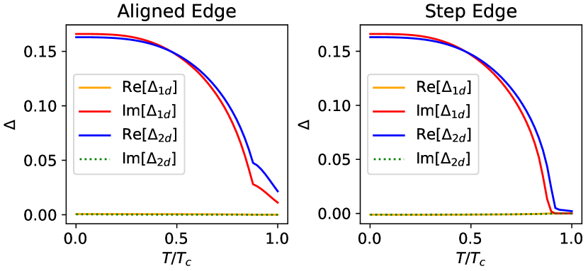
Let us first look at the bulk superconducting order parameters in this configuration. Our self-consistent calculations for each monolayer, reveal that considering nearest-neighbor attractive pairing adequately stabilizes a -wave pairing state in the bulk for a strip width . This state is sustained in each monolayer, across temperatures up to , with the maximum bulk gap of approximately meV at low temperatures. With the chemical potential set to , introducing weak interlayer coupling yields a order parameter in layer 1 and a order parameter in layer 2, exhibiting a relative phase of . This is illustrated in Fig. 2 where we plot the onsite order parameters defined within the bulk.
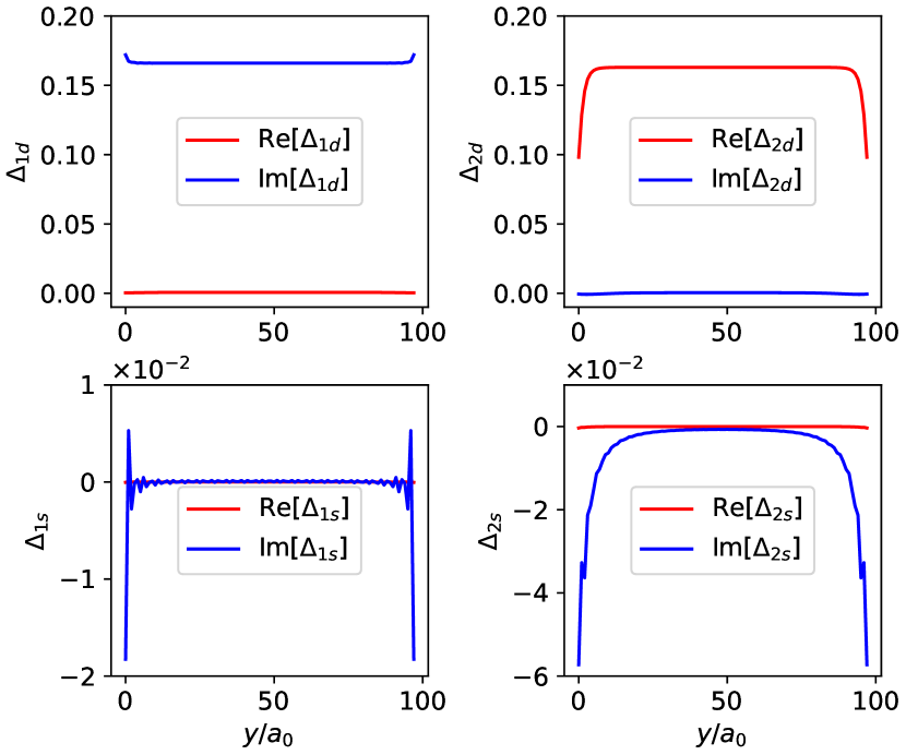
The spatial profile of the order parameters is shown in Fig. 3. The edge is pair-breaking for the order parameter in layer 2. This leads to a suppression of near the edge and a nucleation of an extended -wave order parameter in layer 2. The phase difference between the -wave order parameter and the order parameter is , giving rise to the order parameter in layer 2 near the edge. This is a manifestation of the pair-breaking edge physics explored previously in Ref. [26]. This local -breaking occurs already for a single-layer SC and is not relevant to our discussion of edge currents in the chiral phase in twisted bilayer. The effect complicates our analysis of the bilayer as the order parameter is time-reversal symmetry breaking and can give rise to significant edge currents, a topic addressed in Sec. III. For this reason we focus in the following on types of edges that are not pair breaking and therefore avoid formation of the local phase.
II.3.2 Step edge configuration
Next, we consider a step edge configuration in which the layer 1 with the order parameter covers half of the long strip width as shown in Fig. 1(c). This type of edge is likely to occur in a real experimental setup where the twisted bilayer is fabricated using the cleave-and-stack technique. Importantly, the edge of this type avoids the effects due to the pair breaking boundary by keeping the order parameter nearly uniform.
We model this configuration in the long strip geometry with a width of and maintain periodic boundary conditions along the -direction in both layers. In layer 1, we impose a large potential barrier across half the strip, precluding the emergence of order parameter in the region with the barrier. We model this barrier as
| (8) |
with .
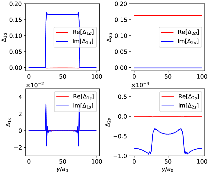
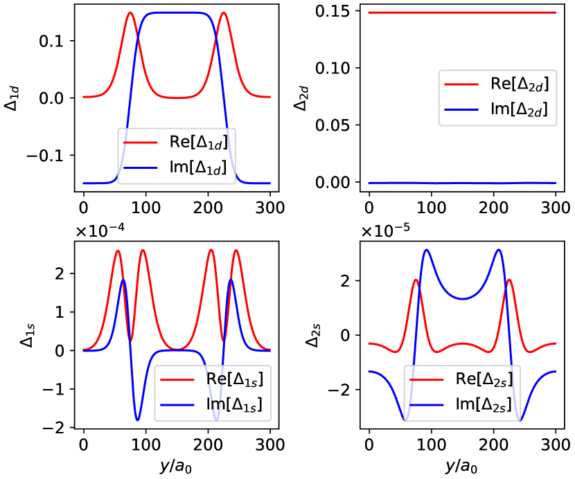
The self-consistent solution yields a order parameter in the bulk, as shown in Fig. 2. We obtain step edges of the order parameter in layer 1 at and while generating a nearly uniform order parameter in layer 2 without any edges, as depicted in Fig. 4.
The pair-breaking edges of the monolayer are absent in this configuration, leading to the reduction in the magnitude of the extended -wave order parameter. The magnitude of the extended -wave order parameter is about 100 times smaller than that in the aligned edge configuration. The contribution of the order parameter to the current in the system is negligible as we will demonstrate in Sec. III. Therefore, the step edge configuration can be used to examine the edge currents intrinsic to the chiral superconductor formed in a twisted bilayer.
II.3.3 Domain wall
Domain walls can form between and phases when there is a weak in-plane magnetic field modulating the relative phase or when the system is rapidly cooled. The Chern number for each domain is , respectively. A domain wall separating and regions therefore hosts twice as many edge modes compared to the ordinary edge, leading to a larger supercurrent. This configuration is illustrated in Fig. 1(d).
To avoid pair breaking effects we create domain walls in the order parameter in our system by imposing the following initial ansatz,
| (9) |
Evidently, the domain walls are present at and . We take periodic boundary conditions along the -direction in both layers.
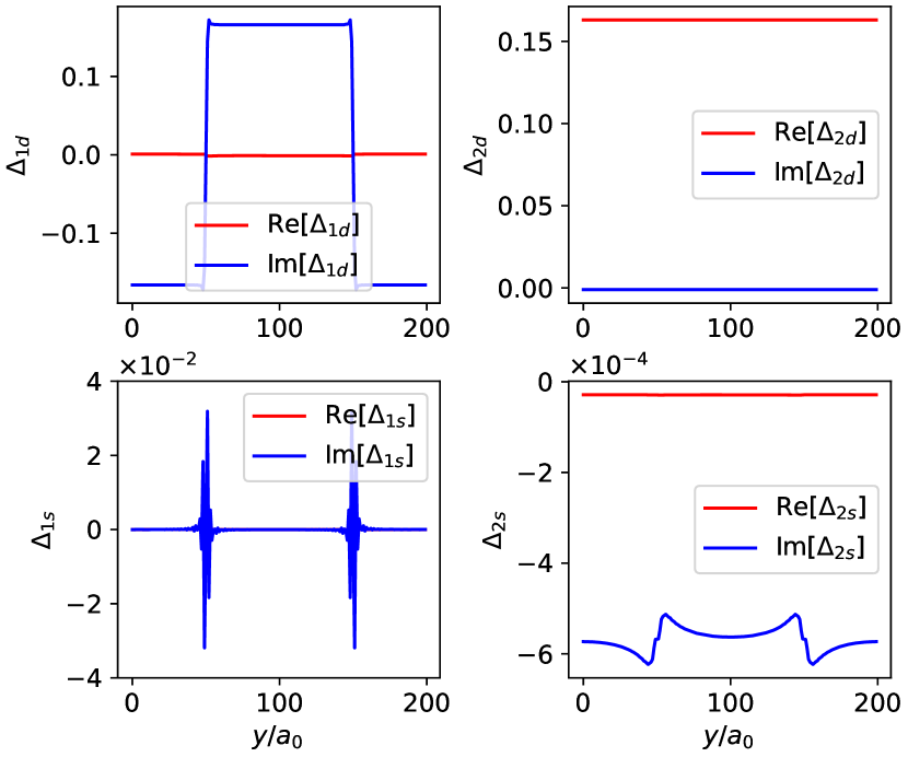
In the bulk, our self-consistent solution Fig. 5 gives a nearly uniform order parameter in layer 2 and, depending on the domain, a order parameter in layer 1. In the absence of any pinning potential, we observe that the system prefers to keep the magnitude of the order parameter constant and vary the phase, thus creating a phase domain wall. The order parameter remains nearly constant as there is no pair breaking edge present in the system. The extended -wave in layer 2 is about 1000 times smaller than that found in the aligned edge configuration.
We can also pin the domain walls using a potential to suppress the order parameters locally along a line. In this case, the magnitude of the order parameter goes to zero at the domain wall, creating an amplitude wall. We show the order parameters of the pinned domain wall in Fig. 6.
For the discussion that follows, we refer to the domain wall in the absence of pinning potential as ‘free domain wall’ and that with a pinning potential as a ‘pinned domain wall’. The two domain walls exhibit notable differences in the spatial profile of the supercurrent as we will discuss in Sec. III.
III Edge currents
III.1 Current operator
The current flowing along a bond between sites and in the tight binding model Eq. (1) is most easily obtained by performing the Peierls substitution where is the vector potential integrated along the bond. The current operator then follows from
| (10) |
and the last expression holds when sites and are nearest neighbors. Given the BdG eigenstates at temperature it is straightforward to evaluate the expected value of the current operator Eq. (10) for any bond. By symmetry and current conservation, we only expect non-zero currents to flow along the in-plane bonds that are parallel to the edge.
III.2 Current from spectral function
Before we present our results for edge current magnitudes we digress briefly to relate the edge current to the electron spectral function . The latter can be used to visualize the chiral edge modes and hence the relation offers a way to understand the origin of the edge current. We shall also see that this approach helps to rationalize the disparity between the robust edge currents expected in the () case and a relatively weak current predicted for the () chiral superconductor. We remark that previous studies noted this disparity but did not provide a simple physical picture that would explain its origin [2, 8].
For a long strip geometry where crystal momentum along is a good quantum number, starting from Eq. (10) we can derive a mixed representation expression for the current along a horizontal bond at distance from the edge in terms of the spectral function,
| (11) |
Here the trace extends over layer and BdG indices while
| (12) |
is the spectral function evaluated at distance from the edge. is the matrix Hamiltonian describing the strip and denotes a positive infinitesimal. Subscript indicates that a diagonal block of the matrix at spatial position is to be taken. Individual elements of each such block can be thought of as position- and layer-resolved normal and anomalous components of the Gorkov Green’s function . Details of the derivation are given in Appendix A.
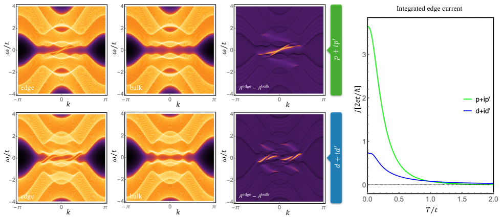
Figure 7 shows spectral fuctions calculated from our bilayer model for both and chiral superconductors. In accord with the expectations spectral functions show unidirectional modes when evaluated near the edge of the strip and they show fully gapped spectrum in the bulk. We note that for bilayer Chern number and 2 phases are possible, depending on the model parameters [31], while for one can get [9]. We chose to display a phase for and for here.
Because no current flows in the bulk of the strip one can subtract from the edge spectral function in the argument of the trace in Eq. (11) without changing the result. Here denotes a position sufficiently far from the edge. Such bulk-subtracted edge spectral functions therefore help visualize the origin of the edge currents and are displayed in the third column of Fig. 7. We observe that for both and 2 the edge currents are sourced primarily from the edge modes, as expected.
Furthermore, combined with Eq. (11) the spectral function plots help understand some important differences between and cases. Specifically, we note that edge modes in the case are antisymmetric about the origin and so is the factor in Eq. (11). Hence once expects in this case a large contribution to the edge current after integration over . On the other hand edge modes in the case lack this antisymmetry; instead we see that contributions from edge modes at positive and negative will tend to cancel as they come with opposite signs after being multiplied by . Indeed as illustrated in the rightmost panel of Fig. 7 the integrated edge current calculated from Eq. (11) is about factor of 4 larger for than for this specific choice of parameters. We note that, for the sake of simplicity, in this calculation the gap amplitudes are taken as -independent and uniform across the width of the strip; the temperature dependence of comes entirely from the Fermi factor in Eq. (11). Results for based on fully self-consistent calculations with realistic parameters will be presented in the next subsection.
III.3 Edge currents: quantitative results
Now, we calculate the edge currents in the long strip geometry of the superconducting heterostructure based on fully self-consistent solutions of the BdG theory with parameters relevant to Bi-2212 bilayer. We compute the supercurrents along the periodic direction as a function of for the strip geometry with finite width along for the three current-carrying configurations described in Sec. II.3. We discuss the current density and use the net supercurrent associated with a given edge, that we define as , to quantify the edge currents.
III.3.1 Aligned edge configuration
We begin with the simplest case, the aligned edge configuration, and present the supercurrent profile as a function of and the net supercurrent versus temperature in Fig. 8. For the aligned edge configuration, the supercurrents are localized in a narrow region at the common edges of both layers and decay exponentially into the bulk. For low temperatures, we observe that the magnitude of the net supercurrents in this configuration is significant for different values of interlayer couplings, . However, upon decreasing the value of from meV to meV, we do not observe any significant change in the magnitude of these supercurrents. Even at low values of , we still get the same magnitude of the supercurrents, an effect that persists up to . We have confirmed that these supercurrents come almost entirely from the monolayer. We thus identify the origin of these supercurrents as the time-reversal breaking order parameter nucleated at the pair-breaking edges. As discussed in the previous Section this effect is unrelated to the chiral phase in twisted bilayer.
In the inset of Fig. 8, we focus on the temperature regime where, according to Ref. [26] and our own calculations, the edge state should be absent. We observe that the magnitude of the net supercurrent decreases with decreasing , a behavior expected at an edge of a bilayer with the chiral superconducting order. In addition we note that when the extended -wave dominates at the edges, the net supercurrent reverses the direction. The transition temperature, , remains constant for a range of interlayer coupling parameters , consistent with the fact that the order occurs already in the monolayer limit.
III.3.2 Step edge configuration
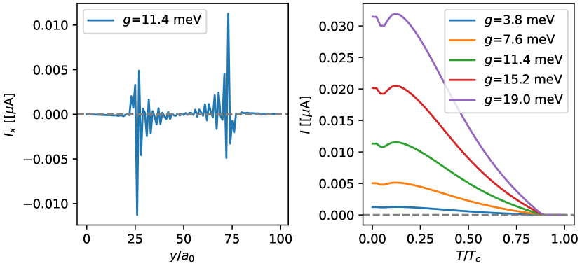
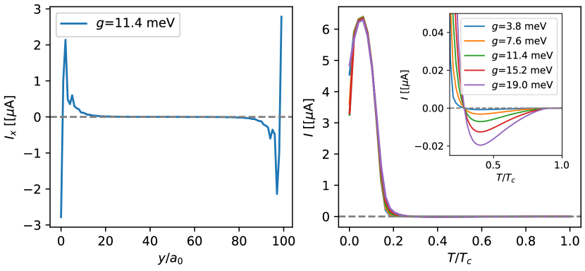
We now analyze the edge currents in the step edge configuration. Here, we avoid the pair-breaking edge of the order parameter by considering step edges in the layer. In Fig. 9 we plot and analyze the net current as a function of temperature and interlayer coupling parameter. With the step edges of order parameter located at and , we find that the supercurrents are localized near these edges and decay into the bulk of the region between the two edges. Note that there is no supercurrent present in the bulk of the pure order parameter.
The net edge current is found to generally decrease with an increasing temperature. Further, as we decrease the inter-layer coupling from 19 meV to 4 meV, we find that the net supercurrent hosted in the system decreases at all temperatures. In the absence of interlayer coupling, i.e. at , the supercurrents vanish. Therefore, the supercurrents present in this system arise solely due to the time-reversal breaking of the order parameter, unlike those emerging at the aligned edges. As the magnitude of the extended -wave order parameter is very small for this configuration, the contribution to the supercurrents from a possible time-reversal breaking order parameter is negligible.
For temperatures below and for 10 to 20 meV, we estimate the net supercurrents hosted at the edge of the twisted cuprate bilayers to be between 10 to 30 nA for realistic parameters.
III.3.3 Domain wall configuration
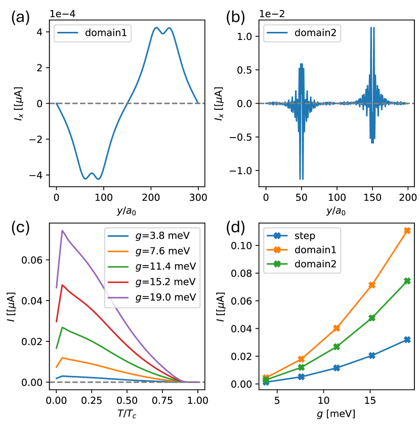
Finally, we investigate supercurrents generated by the two types of a domain wall. We show the current profile and the net current associated with the free domain wall as well as the pinned domain wall in Fig. 10.
In the pinned domain wall, the amplitude of the order parameter goes to zero, whereas it remains constant in the absence of pinning, where a phase domain wall is energetically more stable. As a result, the supercurrent profiles as a function of the position differ significantly for the two domain wall configurations. Supercurrents are highly localized and decay quickly into the bulk near the pinned domain wall, similar to the step edge configuration. In the absence of pinning, currents are still maximal at the domain wall but spread out significantly more into the bulk. These differences are related to the contrasting order parameter profiles for the two types of domain walls shown in Figs. 5 and 6; the phase domain wall is clearly much broader than the amplitude domain wall.
Since the domain wall contains twice the number of protected chiral modes as compared to an edge, we expect the supercurrents to be larger than those generated by the step edge configuration. This is indeed the case, as the net current associated with the pinned domain wall is at least twice that of the step edge configuration, reaching peak values between nA for interlayer couplings ranging from meV to meV. The supercurrents reduce to zero as the interlayer coupling value decreases to zero, which is what we expect in the case of a state in a bilayer. We also find that the supercurrents of the phase domain wall are slightly larger than those at the amplitude domain wall.
Overall, the net supercurrents in pinned and free domain walls increase as the temperature decreases. However, below , the supercurrents in the pinned domain wall exhibit a dip in magnitude. As for the free domain wall, we observe that the domain wall thickness increases with temperature, leading to finite size effects in our model at higher temperatures. Nevertheless, our system sizes can accurately represent domain walls present in a superconductor at low temperatures (below ) relevant to experimental observations discussed below.
IV Estimation of magnetic fields generated by edge currents
The edge currents produced in a time-reversal breaking chiral superconductor will necessarily produce a magnetic field that can, in principle, be detected by state-of-the-art magnetic probes [32, 33, 34]. A possible way to detect the magnetic fields due to the edge currents is by using a scanning superconducting quantum interference device (SQUID) microscope. A DC SQUID consists of a superconducting loop, interrupted by two Josephson junctions. The critical current and voltage drop across the device are periodic in the external magnetic flux. The sensitivity and versatility of scanning SQUID have been instrumental in noninvasive measurements of a broad range of electronic orders such as those in unconventional superconductivity [35, 36], exotic magnetism [37], topological states [38], and more [39].
As demonstrated in the previous Section currents generated by the step edge or pinned domain wall decay over tens of lattice sites, which corresponds to a lengthscale of several nm. A typical magnetic field sensor is located at a height nm above the sample. In this geometry, the edge current can be treated as a line current concentrated at the edge for all practical purposes [34]. We thus model the edge as a thin long wire along carrying the net current , located at . The magnetic field generated by this line current at height above the sample can be deduced from Ampére’s law and is given by
| (13) |
where denotes the lateral position of the sensor and is the radial distance from the wire. Currents associated with the phase domain wall are spread out over a wider lengthscale so the the above thin-wire approximation becomes less accurate. Nevertheless, it should still provide a reasonable estimate for the magnetic field strength.
The flux picked up by the SQUID loop arises from the component of the magnetic field in Eq. (13). The minimal sensor-sample distance depends on the SQUID design which typically balances spatial resolution and magnetic field sensitivity [39, 34]. For planar SQUID, this distance is 100-500 nm [40, 41], while for SQUID-on-tip and nano-SQUID, it is 20-100 nm [42, 38].
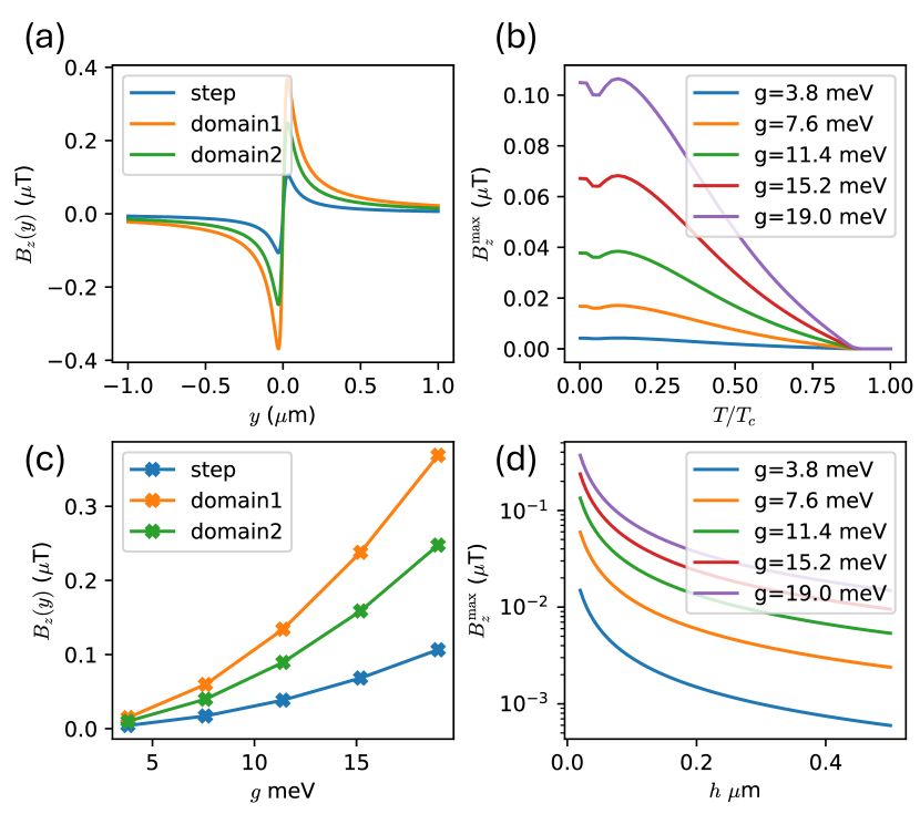
We calculate the magnetic fields generated from the step edge and the domain wall edge of the bilayer. In Fig. 11, we present the magnetic field profiles for the step edge, free domain wall, and the pinned domain wall at a height of 30 nm from the sample, as a function of . We also plot the peak magnetic field generated at the step edge as a function of temperature and confirm that the peak magnetic field shows similar features as the supercurrent plot in Fig. 9. Additionally, we plot the peak magnetic field for the step edge and domain wall edges as a function of interlayer coupling.
Our estimates indicate that a magnetic sensor positioned at a height of 30 nm from the sample would detect magnetic fields of 20-100 nT at the step edge, 50-250 nT at the pinned domain wall, and 80-400 nT at the free domain wall, for realistic interlayer coupling values between 10-20 meV. These values are slightly above the detection threshold of current state-of-the-art nano-SQUIDs [38].
We also show in Fig. 11 the variation of the peak magnetic field with the vertical height of the sample for a representative edge (pinned domain wall). The order of magnitude of the magnetic field remains around nT below a height of 100 nm which is at the detection threshold of nano-SQUIDs. The magnetic field decreases to nT for realistic values of interlayer coupling going from 100 to 500 nm height where planar SQUIDs typically operate.
V Discussion and Summary
The twisted bilayer cuprate system breaks time-reversal symmetry due to the formation of superconducting order parameter. Our work analyzes the edge currents that arise in such a chiral superconductor and can be probed experimentally as a signature of the chiral phase.
We study this system using an aligned lattice model where the -wave superconducting pairing occurs on the nearest-neighbor bonds in one layer and on the next-nearest neighbor bonds in the second layer, mimicking the and the order parameters respectively while avoiding the complications arising from large moiré unit cell. Working with the long strip geometry periodic along the -direction and a finite width along the -direction we study three different edge configurations and calculate the supercurrents flowing in the -direction in each of these geometries. We also relate the edge currents to the spectral function in a generic chiral superconductor and provide an intuitive picture for their difference in magnitudes in the and a case. We use realistic parameters to model the supercurrents at the edge of the twisted cuprate bilayers using a fully self-consistent model.
The aligned edge configuration corresponds to the scenario where the edges of the two layers are perfectly aligned. In accord with previous work [26, 27, 28, 29] we find that a significant extended -wave order parameter develops at the pair-breaking edge of the monolayer resulting in the nucleation of a time-reversal breaking order parameter locally at the edge. We further find that the main contribution to the current for this edge configuration arises from this order parameter, which is in itself interesting but unrelated to the bulk phase of interest here. To study the edge currents and resultant magnetic fields arising due to the bulk order we therefore focus on two other types of linear defects, the step edge and the domain wall.
The step edge configuration features a sharp boundary in the order parameter but avoids the pair-breaking edge in the monolayer. The supercurrents at these step edges arise solely due to the bulk order parameter. For realistic parameters relevant to twisted bilayer cuprates, we estimate the supercurrents from this configuration to be 10-30 nA. Near domain walls we observe supercurrents that are at least twice the magnitude of those present at the step edges, with some notable differences in the local current density profiles between free and pinned domain walls.
Finally, we provide estimates of the magnetic fields generated by the supercurrents at the edges. At the height of 30 nm above the sample, characteristic of the nanoSQUID experiment, we estimate 40-400 nT peak magnetic fields generated by a step edge, free domain wall, or pinned domain wall configuration in the superconducting phase. This places the edge currents in twisted Bi2Sr2CaCu2O8+x bilayers within the realm of what is currently observable using the state of the art scanning magnetometry. The principal source of uncertainty entering the field strength estimate is the magnitude of the interlayer tunneling amplitude on which the edge current depends strongly. The range of values quoted above corresponds to the range of meV spanning its most likely value consistent with transport measurements. By contrast, the edge current shows only weak dependence on other system features, such as the detailed shape of the Fermi surface and the size of the gap. The parameters underlying these features are also much better known for Bi2Sr2CaCu2O8+x and other cuprates.
In closing we wish to remark on the general significance of these findings. As of this writing twisted cuprate bilayers constitute the most plausible candidate for a topological superconductor in two dimensions and the sole known candidate for a high-temperature topological superconductor. Ref. [10] provided strong evidence for spontaneous breaking in high-quality Bi-2212 junctions near twist which is a basic pre-requisite for the chiral phase. However, to directly probe topology it is necessary to detect the protected chiral edge modes which is a more delicate task. Edge modes in a topological superconductor carry quantized heat current but this is exceedingly difficult to measure. The associated persistent electrical current is not quantized but may be more easily observed. As argued in this work edge currents produce magnetic fields of tens to hundreds of nT which is above the detection threshold of modern magnetometry techniques. As we emphasized, an important caveat will be to stay away from pair-breaking edges which tend to produce even larger edge currents through a physically distinct mechanism that applies already in the monolayer limit. Such currents are independently interesting but are unrelated to the chiral phase that is only expected to occur in twisted bilayers.
Detection of edge currents in twisted cuprate bilayers thus poses a significant experimental challenge but it is a challenge well worth pursuing. The high-temperature topological phase predicted to occur near the twist has been extensively discussed in the literature as basis for a number of novel phenomena and applications. These include charge-4 superconductivity [43], higher order topology [44], fractional and coreless vortices [25] and Majorana fermions [45, 46]. In addition, the idea of assembling superconducting monolayers with a twist has numerous interesting applications outside the realm of high- cuprates; these include twisted iron-based bilayers [47], non-abelian topology in twisted spin-singlet valley-triplet superconductors [48] and related innovative proposals [49, 50], as well as a proposed application to improve the performance of transmon qubits [51, 52] which power the large majority of superconducting quantum processors currently in operation.
VI Acknowledgments
We thank Catherine Kallin, Thomas Scaffidi, Alberto Nocera, Niclas Heinsdorff, Nitin Kaushal and Aviram Uri for helpful discussions and correspondence. This work was supported by NSERC, CIFAR and the Canada First Research Excellence Fund, Quantum Materials and Future Technologies Program. M.F. thanks the Aspen Center for Physics where part of this work was completed.
References
- Stone and Roy [2004] M. Stone and R. Roy, Edge modes, edge currents, and gauge invariance in superfluids and superconductors, Phys. Rev. B 69, 184511 (2004).
- Huang et al. [2014] W. Huang, E. Taylor, and C. Kallin, Vanishing edge currents in non--wave topological chiral superconductors, Phys. Rev. B 90, 224519 (2014).
- Kallin and Berlinsky [2016] C. Kallin and J. Berlinsky, Chiral superconductors, Reports on Progress in Physics 79, 054502 (2016).
- Huang et al. [2015] W. Huang, S. Lederer, E. Taylor, and C. Kallin, Nontopological nature of the edge current in a chiral -wave superconductor, Phys. Rev. B 91, 094507 (2015).
- Rainer et al. [1998] D. Rainer, H. Burkhardt, M. Fogelström, and J. Sauls, Andreev bound states, surfaces and subdominant pairing in high tc superconductors, Journal of Physics and Chemistry of Solids 59, 2040 (1998).
- Horovitz and Golub [2003] B. Horovitz and A. Golub, Superconductors with broken time-reversal symmetry: Spontaneous magnetization and quantum hall effects, Phys. Rev. B 68, 214503 (2003).
- Braunecker et al. [2005] B. Braunecker, P. A. Lee, and Z. Wang, Edge currents in superconductors with a broken time-reversal symmetry, Phys. Rev. Lett. 95, 017004 (2005).
- Suzuki and Asano [2016] S.-I. Suzuki and Y. Asano, Spontaneous edge current in a small chiral superconductor with a rough surface, Phys. Rev. B 94, 155302 (2016).
- Can et al. [2021a] O. Can, T. Tummuru, R. P. Day, I. Elfimov, A. Damascelli, and M. Franz, High-temperature topological superconductivity in twisted double-layer copper oxides, Nature Physics 17, 519 (2021a).
- Zhao et al. [2023] S. Y. F. Zhao, X. Cui, P. A. Volkov, H. Yoo, S. Lee, J. A. Gardener, A. J. Akey, R. Engelke, Y. Ronen, R. Zhong, G. Gu, S. Plugge, T. Tummuru, M. Kim, M. Franz, J. H. Pixley, N. Poccia, and P. Kim, Time-reversal symmetry breaking superconductivity between twisted cuprate superconductors, Science 382, 1422 (2023).
- Volkov et al. [2023a] P. A. Volkov, Étienne Lantagne-Hurtubise, T. Tummuru, S. Plugge, J. H. Pixley, and M. Franz, Josephson diode effects in twisted nodal superconductors (2023a), arXiv:2307.01261 [cond-mat.supr-con] .
- Zhu et al. [2021] Y. Zhu, M. Liao, Q. Zhang, H.-Y. Xie, F. Meng, Y. Liu, Z. Bai, S. Ji, J. Zhang, K. Jiang, R. Zhong, J. Schneeloch, G. Gu, L. Gu, X. Ma, D. Zhang, and Q.-K. Xue, Presence of -wave pairing in josephson junctions made of twisted ultrathin flakes, Phys. Rev. X 11, 031011 (2021).
- Wang et al. [2023] H. Wang, Y. Zhu, Z. Bai, Z. Wang, S. Hu, H.-Y. Xie, X. Hu, J. Cui, M. Huang, J. Chen, Y. Ding, L. Zhao, X. Li, Q. Zhang, L. Gu, X. J. Zhou, J. Zhu, D. Zhang, and Q.-K. Xue, Prominent josephson tunneling between twisted single copper oxide planes of bi2sr2-xlaxcuo6+y, Nature Communications 14, 5201 (2023).
- Martini et al. [2023] M. Martini, Y. Lee, T. Confalone, S. Shokri, C. N. Saggau, D. Wolf, G. Gu, K. Watanabe, T. Taniguchi, D. Montemurro, V. M. Vinokur, K. Nielsch, and N. Poccia, Twisted cuprate van der waals heterostructures with controlled josephson coupling, Materials Today 67, 106 (2023).
- Song et al. [2022] X.-Y. Song, Y.-H. Zhang, and A. Vishwanath, Doping a moiré mott insulator: A model study of twisted cuprates, Phys. Rev. B 105, L201102 (2022).
- Lu and Sénéchal [2022] X. Lu and D. Sénéchal, Doping phase diagram of a hubbard model for twisted bilayer cuprates, Phys. Rev. B 105, 245127 (2022).
- Fidrysiak et al. [2023] M. Fidrysiak, B. Rzeszotarski, and J. Spałek, Tuning topological superconductivity within the model of twisted bilayer cuprates, Phys. Rev. B 108, 224509 (2023).
- Volkov et al. [2023b] P. A. Volkov, J. H. Wilson, K. P. Lucht, and J. H. Pixley, Magic angles and correlations in twisted nodal superconductors, Phys. Rev. B 107, 174506 (2023b).
- Bélanger and Sénéchal [2024a] M. Bélanger and D. Sénéchal, Interlayer bias effect on time-reversal symmetry breaking in twisted bilayer cuprates, Phys. Rev. B 109, 075111 (2024a).
- Bélanger and Sénéchal [2024b] M. Bélanger and D. Sénéchal, Doping dependence of chiral superconductivity in near twisted bilayer cuprates, Phys. Rev. B 109, 045111 (2024b).
- Haenel et al. [2022] R. Haenel, T. Tummuru, and M. Franz, Incoherent tunneling and topological superconductivity in twisted cuprate bilayers, Phys. Rev. B 106, 104505 (2022).
- Yuan et al. [2023] A. C. Yuan, Y. Vituri, E. Berg, B. Spivak, and S. A. Kivelson, Inhomogeneity-induced time-reversal symmetry breaking in cuprate twist junctions, Phys. Rev. B 108, L100505 (2023).
- Volkov et al. [2023c] P. A. Volkov, J. H. Wilson, K. P. Lucht, and J. H. Pixley, Current- and field-induced topology in twisted nodal superconductors, Phys. Rev. Lett. 130, 186001 (2023c).
- Can et al. [2021b] O. Can, X.-X. Zhang, C. Kallin, and M. Franz, Probing time reversal symmetry breaking topological superconductivity in twisted double layer copper oxides with polar kerr effect, Phys. Rev. Lett. 127, 157001 (2021b).
- Holmvall et al. [2023] P. Holmvall, N. Wall-Wennerdal, and A. M. Black-Schaffer, Robust and tunable coreless vortices and fractional vortices in chiral -wave superconductors, Phys. Rev. B 108, 094511 (2023).
- Håkansson et al. [2015] M. Håkansson, T. Löfwander, and M. Fogelström, Spontaneously broken time-reversal symmetry in high-temperature superconductors, Nature Physics 11, 755 (2015).
- Holmvall et al. [2018] P. Holmvall, A. B. Vorontsov, M. Fogelström, and T. Löfwander, Broken translational symmetry at edges of high-temperature superconductors, Nature Communications 9, 2190 (2018).
- Holmvall et al. [2019] P. Holmvall, A. B. Vorontsov, M. Fogelström, and T. Löfwander, Spontaneous symmetry breaking at surfaces of -wave superconductors: Influence of geometry and surface ruggedness, Phys. Rev. B 99, 184511 (2019).
- Wennerdal et al. [2020] N. W. Wennerdal, A. Ask, P. Holmvall, T. Löfwander, and M. Fogelström, Breaking time-reversal and translational symmetry at edges of -wave superconductors: Microscopic theory and comparison with quasiclassical theory, Phys. Rev. Res. 2, 043198 (2020).
- Tummuru et al. [2022] T. Tummuru, S. Plugge, and M. Franz, Josephson effects in twisted cuprate bilayers, Phys. Rev. B 105, 064501 (2022).
- Tummuru et al. [2021] T. Tummuru, O. Can, and M. Franz, Chiral -wave superconductivity in a twisted array of proximitized quantum wires, Phys. Rev. B 103, L100501 (2021).
- Hartmann [1999] U. Hartmann, Magnetic force microscopy, Annual Review of Materials Science 29, 53 (1999).
- Casola et al. [2018] F. Casola, T. van der Sar, and A. Yacoby, Probing condensed matter physics with magnetometry based on nitrogen-vacancy centres in diamond, Nature Reviews Materials 3, 17088 (2018).
- Kirtley [2010] J. R. Kirtley, Fundamental studies of superconductors using scanning magnetic imaging, Reports on Progress in Physics 73, 126501 (2010).
- Tsuei et al. [1994] C. C. Tsuei, J. R. Kirtley, C. C. Chi, L. S. Yu-Jahnes, A. Gupta, T. Shaw, J. Z. Sun, and M. B. Ketchen, Pairing symmetry and flux quantization in a tricrystal superconducting ring of , Phys. Rev. Lett. 73, 593 (1994).
- Kalisky et al. [2011] B. Kalisky, J. R. Kirtley, J. G. Analytis, J.-H. Chu, I. R. Fisher, and K. A. Moler, Behavior of vortices near twin boundaries in underdoped ba(fe, Phys. Rev. B 83, 064511 (2011).
- Christensen et al. [2019] D. V. Christensen, Y. Frenkel, Y. Z. Chen, Y. W. Xie, Z. Y. Chen, Y. Hikita, A. Smith, L. Klein, H. Y. Hwang, N. Pryds, and B. Kalisky, Strain-tunable magnetism at oxide domain walls, Nature Physics 15, 269 (2019).
- Uri et al. [2020] A. Uri, Y. Kim, K. Bagani, C. K. Lewandowski, S. Grover, N. Auerbach, E. O. Lachman, Y. Myasoedov, T. Taniguchi, K. Watanabe, J. Smet, and E. Zeldov, Nanoscale imaging of equilibrium quantum Hall edge currents and of the magnetic monopole response in graphene, Nature Physics 16, 164 (2020).
- Persky et al. [2022] E. Persky, I. Sochnikov, and B. Kalisky, Studying quantum materials with scanning squid microscopy, Annual Review of Condensed Matter Physics 13, 385 (2022).
- Kirtley et al. [2016] J. R. Kirtley, L. Paulius, A. J. Rosenberg, J. C. Palmstrom, C. M. Holland, E. M. Spanton, D. Schiessl, C. L. Jermain, J. Gibbons, Y.-K.-K. Fung, M. E. Huber, D. C. Ralph, M. B. Ketchen, J. Gibson, Gerald W., and K. A. Moler, Scanning SQUID susceptometers with sub-micron spatial resolution, Review of Scientific Instruments 87, 093702 (2016).
- Cui et al. [2017] Z. Cui, J. R. Kirtley, Y. Wang, P. A. Kratz, A. J. Rosenberg, C. A. Watson, J. Gibson, Gerald W., M. B. Ketchen, and K. A. Moler, Scanning SQUID sampler with 40-ps time resolution, Review of Scientific Instruments 88, 083703 (2017).
- Vasyukov et al. [2013] D. Vasyukov, Y. Anahory, L. Embon, D. Halbertal, J. Cuppens, L. Neeman, A. Finkler, Y. Segev, Y. Myasoedov, M. L. Rappaport, M. E. Huber, and E. Zeldov, A scanning superconducting quantum interference device with single electron spin sensitivity, Nature Nanotechnology 8, 639 (2013).
- Liu et al. [2023a] Y.-B. Liu, J. Zhou, C. Wu, and F. Yang, Charge-4e superconductivity and chiral metal in 45-twisted bilayer cuprates and related bilayers, Nature Communications 14, 7926 (2023a).
- Li and Liu [2023] Y.-X. Li and C.-C. Liu, High-temperature majorana corner modes in a superconductor heterostructure: Application to twisted bilayer cuprate superconductors, Phys. Rev. B 107, 235125 (2023).
- Margalit et al. [2022] G. Margalit, B. Yan, M. Franz, and Y. Oreg, Chiral majorana modes via proximity to a twisted cuprate bilayer, Phys. Rev. B 106, 205424 (2022).
- Mercado et al. [2022] A. Mercado, S. Sahoo, and M. Franz, High-temperature majorana zero modes, Phys. Rev. Lett. 128, 137002 (2022).
- Eugenio and Vafek [2023] P. M. Eugenio and O. Vafek, Twisted-bilayer FeSe and the Fe-based superlattices, SciPost Phys. 15, 081 (2023).
- Zhou et al. [2023] B. T. Zhou, S. Egan, D. Kush, and M. Franz, Non-abelian topological superconductivity in maximally twisted double-layer spin-triplet valley-singlet superconductors, Communications Physics 6, 47 (2023).
- Liu et al. [2023b] Y.-B. Liu, J. Zhou, Y. Zhang, W.-Q. Chen, and F. Yang, Making chiral topological superconductors from nontopological superconductors through large angle twists, Phys. Rev. B 108, 064508 (2023b).
- Lin et al. [2023] C. Lin, C. Huang, and X. Lu, Customizing topological phases in the twisted bilayer superconductors with even-parity pairings, Chinese Physics B 32, 087401 (2023).
- Brosco et al. [2024] V. Brosco, G. Serpico, V. Vinokur, N. Poccia, and U. Vool, Superconducting qubit based on twisted cuprate van der waals heterostructures, Phys. Rev. Lett. 132, 017003 (2024).
- Patel et al. [2024] H. Patel, V. Pathak, O. Can, A. C. Potter, and M. Franz, -mon: A transmon with strong anharmonicity based on planar -axis tunneling junction between -wave and -wave superconductors, Phys. Rev. Lett. 132, 017002 (2024).
Appendix A Edge current from spectral function
In this Section we give details pertaining to the derivation of Eq. (11). We begin by rewriting Eq. (10) for the bond current operator as
| (14) |
where we defined a Nambu spinor . To avoid clutter we focus here on the current in a single layer and take . Regarding as a field operator in imaginary time we can further express the current expectation value as
| (15) |
where denotes the imaginary time Gorkov Green’s function.
For a long strip geometry it is convenient to switch to a notation there denotes the position of site . The current along an -bond distance from the edge can then be expressed as
| (16) |
Exploiting translation invariance along we introduce mixed Fourier representation and obtain for the current
| (17) |
As the final step we pass to the Matsubara frequency and express in terms of its spectral representation
| (18) |
with . Here denotes the retarded Green’s function obtained from by analytic continuation . Substituting Eq. (18) to (17) and performing the required Matsubara sum using
| (19) |
we obtain Eq. (11) of the main text.