abbreviationindexonlyfirsttrue \glssetcategoryattributeabbreviationnohyperfirsttrue \newabbreviationaurocAUROCArea Under the Receiver Operating Characteristic Curve \newabbreviationaccuracyAccAccuracy \newabbreviationateATEAbsolute Trajectory Error \newabbreviationbevBEVBird-Eye View \newabbreviationclipCLIPContrastive Language-Image Pretraining \newabbreviationcnnCNNConvolutional Neural Network \newabbreviationdofDoFDoF \newabbreviationfovFoVField of View \newabbreviationfprFPRFalse Positive Ratio \newabbreviationgnnGNNGraph Neural Network \newabbreviationgcnGCNGraph Convolutional Network \newabbreviationknnKNNK-Nearest Neighbors \newabbreviation[plural=LLMs,firstplural=Large Language Models]llmLLMLarge Language Model \newabbreviationlidarLiDARLight Detection and Ranging \newabbreviationmlpMLPMulti-Layer Perceptron \newabbreviationmpcMPCModel Predictive Controller \newabbreviationmseMSEMean Squared Error \newabbreviationoodOODout-of-distribution \newabbreviationpcaPCAPrincipal Component Analysis \newabbreviationrbfRBFRadial Basis Function \newabbreviationrmpRMPRiemannian Motion Policies \newabbreviationrmseRMSERoot Mean Square Error \newabbreviationrosROSRobot Operating System \newabbreviationros1ROS 1Robot Operating System \newabbreviationrocROCReceiver Operating Characteristic \newabbreviationrpeRPERelative Pose Error \newabbreviationrfRFRandom Forest \newabbreviationsdfSDFSigned Distance Field \newabbreviationslamSLAMSimultaneous Localization and Mapping \newabbreviationsotaSOTAstate-of-the-art \newabbreviationsvmSVMSupport Vector Machine \newabbreviationsvcSVCSupport Vector Classifier \newabbreviationvitViTVision Transformer \newabbreviationvprVPRVisual Place Recognition \newabbreviationvlmVLMVision-Language Model
Exosense: A Vision-Centric Scene Understanding System For
Safe Exoskeleton Navigation
Abstract
Exoskeletons for daily use by those with mobility impairments are being developed. They will require accurate and robust scene understanding systems. Current research has used vision to identify immediate terrain and geometric obstacles, however these approaches are constrained to detections directly in front of the user and are limited to classifying a finite range of terrain types (e.g., stairs, ramps and level-ground). This paper presents Exosense, a vision-centric scene understanding system which is capable of generating rich, globally-consistent elevation maps, incorporating both semantic and terrain traversability information. It features an elastic Atlas mapping framework associated with a visual SLAM pose graph, embedded with open-vocabulary room labels from a Vision-Language Model (VLM). The device’s design includes a wide field-of-view (FoV) fisheye multi-camera system to mitigate the challenges introduced by the exoskeleton walking pattern. We demonstrate the system’s robustness to the challenges of typical periodic walking gaits, and its ability to construct accurate semantically-rich maps in indoor settings. Additionally, we showcase its potential for motion planning—providing a step towards safe navigation for exoskeletons.
I Introduction
Recent advances in self-balancing exoskeletons, such as the Wandercraft Atalante exoskeleton [1], empower individuals with lower-limb disabilities to walk independently. These powered exoskeletons are typically used in controlled clinical and therapeutic contexts but are moving towards home and outdoor use. At present, they often employ a control scheme with pre-defined gait trajectories which are activated manually using an operator control panel [2] but do not incorporate environment perception into their operation.
Unlocking the opportunities that exoskeletons offer for daily use requires the development of systems capable of perceiving the platform’s surroundings and assisting locomotion accordingly. Existing research has used vision to classify the terrain type (namely stairs, ramps, and level ground walking) [3, 4], to determine basic geometric features such as ground inclination and step height [5], as well as to detect potential obstacles in the environment such as boxes and general clutter [6]. Typically, these approaches focus on detecting and classifying the area directly in front of the user [5].
Meanwhile, research into semantic and 3D scene graphs aims to build a high-level understanding of maps for real-world environments [7]. These approaches could enable exoskeletons to plan over longer horizons and avoid areas that are difficult to access. Nevertheless, these systems typically focus on object or room-level semantics, and represent space as a graph—but do not capture explicit terrain traversability estimates [7].
Integrating advanced perception into exoskeleton devices is challenging. To minimize intrusion to the user and prevent occlusion of vision sensors, one optimal placement is on an exoskeleton’s lower limbs. During locomotion these limbs move with high levels of acceleration and jerk [8]. These design constraints challenge the assumptions of state estimation systems and are rarely considered by semantic SLAM systems.
In this work, we present Exosense, a perception system designed for integration into exoskeleton devices for domestic use. The system generates a rich multi-floor representation using data captured from a wide field-of-view (FoV) multi-sensor wearable prototype. The representation contains not only spatial geometry but also room class labels, and a traversability graph which facilitates room-to-room planning (Fig. LABEL:fig:cover).
Our key contributions are:
-
•
A system to produce multi-floor terrain maps embedded with geometric understanding and open-vocabulary room labels obtained from a Vision-Language Model (VLM) based SLAM module.
-
•
A comprehensive study on the effect of the hardware choice on the performance of the state estimators under the dynamic motion typical of jerky walking pattern.
-
•
A demonstration of hierarchical motion planning on top of the multi-story terrain map produced by the present system, showcasing the system capacity for potential downstream task and progressing a step towards safe navigation of exoskeleton devices.
-
•
Extensive evaluation of the system in an office and home environment.
II Related Work
In this section, we review perception systems designed for exoskeleton applications, as well as leading methods for scene understanding.
II-A Perception for Exoskeletons
Several exoskeleton sensing systems aim to detect relevant ground features for reliable locomotion. Ramanathan et al. [8] developed a vision-based perception system to enable exoskeletons to detect obstacle locations and dimensions, and to change step size accordingly. Karacan et al. [4] used a depth camera and an IMU mounted on a subject’s waist to classify objects (e.g., ramps, staircases, obstacles), and to predict stair height and depth, achieving a mean prediction error value below when compared to ground truth dimensions. They also employed a shared-control framework where users confirm or decline suggested activity modes manually. Similarly, Liu et al. [6] tested an RGB-D camera mounted on the waist to extract ground object features and planned gait patterns autonomously based on environmental feedback. An RGB-D and IMU sensor rig was created by Al-Dabbagh and Ronsse [5] and mounted on a person’s chest for terrain detection in indoor and outdoor environments.
Two other works developed detectors for obstacles relevant to the exoskeleton’s locomotion. Kurbis et al. [3] trained to detect stairs, while Bao et al. [9] used eye-tracking systems to aid in object detection.
Exosense extends these approaches by reconstructing ground features in a persistent map. By building a continuous terrain representation instead of processing frames individually, it can produce a consistent scene representation including both geometric and semantic information, which unlocks the potential for various downstream tasks such as hierarchical motion planning over a longer horizon.
II-B Scene Understanding
This section discusses scene understanding approaches being developed for more general robotics tasks including local terrain representation and global semantic mapping.
Local representations are crucial for facilitating navigation tasks, including path planning. Various representations, such as 2D occupancy grids or volumetric representations [10], and 2.5D elevation terrain maps [11], have been developed to support these tasks. Elevation maps are a preferred choice for ground robots, as evidenced by their adoption in works such as [12, 13, 14].
More recent work has extended elevation maps with semantic information to support autonomous vehicle planning from a birds-eye view, or to capture terrain traversability for walking platforms [15, 16, 17].
Meanwhile, scene understanding systems have been developed to enrich the metric reconstructions provided by systems. 3D scene graphs such as Hydra [7] or S-Graphs [18] have shown how contextual understanding can capture relationships between objects and rooms in hierarchical map models. New representations based on neural fields and such as OpenScene [19], LERF [20], and CLIP-Field [21] can embed VLMs directly into maps to produce semantic segmentations, which can be queried with simple text prompts.
In our work, we integrate both local and global methodologies to build a semantically-enhanced global elevation map representation. This enhanced representation incorporates VLM based open-vocabulary semantic room labels and traversability estimation tailored for exoskeleton navigation.
III System
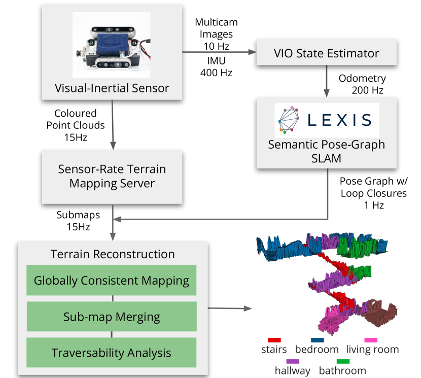
We provide an overview of the Exosense system in Fig. 2. Its inputs are wide FoV images and IMU data for odometry, and point clouds for terrain mapping—all captured by a leg-mounted wearable device (Fig. 1). These inputs are processed by odometry estimation and local terrain mapping modules. Additionally, a pose-graph based visual-language SLAM system is employed to construct a global topological representation, which is used as the backbone on which to generate a cohesive, semantic, multi-floor terrain representation.
III-A Multi-sensor Setup
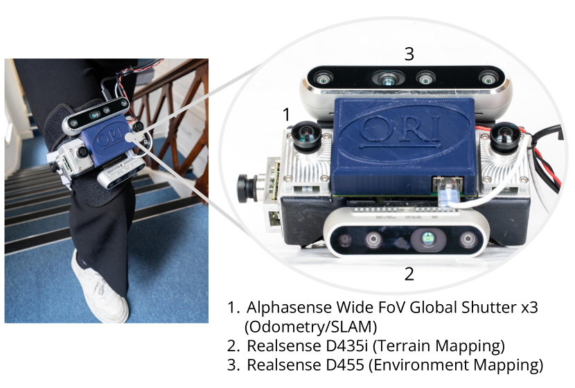
We use a leg-mounted wearable device for our experiments, as shown in Fig. 1. This setup enables us to emulate the gait pattern achieved by exoskeleton platforms, and can effectively be reconfigured and rigidly attached to the lower limb of an exoskeleton, which eventually empower the downstream task such as motion planning.
The sensing device consists of a Sevensense Alphasense unit with three wide-angle global-shutter cameras, and two Realsense RGB-D cameras (D435i and D455). The Alphasense unit consists of a pair of forward-facing stereo cameras and a lateral camera, which is used for state estimation and the semantic SLAM system. The configuration is chosen so as to be able to maintain motion tracking when partially occluded [22] with the wide FoV adding the extra benefit of feature tracking over a prolonged period [23]. In Sec. IV-A, we present a study to showcase the benefits of such design choices under the leg-mounted deployment scenario. Additionally, the Realsense D435i is used for terrain depth sensing, and the D455 for environment sensing in the terrain reconstruction module.
III-B Visual-Inertial Odometry
For motion tracking, we use existing visual-inertial odometry systems. Specifically, we evaluate OpenVINS [24], VILENS-MC [22] and ORB-SLAM [25] in custom sequences recorded with our sensing device to assess their performance and reliability under the high rotation rates and jerk of the exoskeleton walking pattern. Sec. IV-B provides a quantitative comparison of these methods.
III-C Semantic Pose-graph SLAM
The odometry serves as input to our semantic visual pose-graph SLAM system, LEXIS [26].
LEXIS selects from a list of potential room classes (e.g., office, kitchen, corridor) to construct a topological pose graph representation with evenly spaced keyframes. Features are extracted for each keyframe using CLIP [27]. This is followed by a comparison to text encodings generated from the input room list using cosine similarity. Due to the open-vocabulary nature of CLIP, the room labels are not limited to predefined categories, enabling generalization to a wide range of environments.
This room representation is also used to refine the search for loop closures and thereby correct odometry drift. For each new keyframe we determine the current room by searching for all rooms with the same label. Using the current localization estimate we then choose the closest room cluster. Keyframe matches within the room are found by comparing CLIP features using cosine similarity. Geometric verification is then attempted using PnP [28]; if successful, a loop closure is added to the graph.
The output of LEXIS is a segmented pose graph representing the rooms in the environment, where each node consists of a pose in the reference map frame, loop closure information, and a room label associated with the keyframe. More details of this system are presented in the aforementioned paper.
III-D Mapping and Reconstruction
To obtain a globally consistent reconstruction we adopt an elastic approach introduced by the Atlas framework [29]: locally consistent maps are attached to nodes of LEXIS’ pose graph to build a globally accurate terrain map. A high-frequency terrain mapping system () integrates incoming point clouds from both RGB-D cameras to generate a rolling local multi-layered 2.5D map [30] around the device’s location. We use the mapping approach by Fankhauser et al. [11], though other similar approaches such as [15, 17] can also be utilized.
Our mapping server associates the sensor-rate local terrain maps to the nodes of the LEXIS’ pose graph, effectively building a global terrain map of the environment. This enables us to correct the global terrain map every time a loop closure is triggered and the pose graph is corrected.
While this representation enables a lightweight elastic reconstruction, the individual submaps only represent a local region around the corresponding node, which might be suboptimal for downstream planning tasks. We propose a semantically-guided fusion strategy to output a room-consistent representation based on the semantic room labels already encoded in the LEXIS’ pose graph. For nodes within the same room, we iterate over their respective submaps to fuse their terrain map cells, using the median of overlapping height values:
| (1) |
where is the fused height value for the cell of terrain map, is the set of all the valid overlapping height values in cell . In Sec. IV-C we illustrate the outcomes achieved with this fusion strategy across various multi-story datasets.
III-E Terrain Traversability Analysis
Following the room-based fusion step, we then assess the traversability of resultant terrain map. We conduct a geometric analysis of the local terrain tailored to the exoskeleton’s gait specifications. This analysis assigns traversability scores to all cells within the multi-layered 2.5D map representing rooms.
The local terrain analysis module determines a traversability score for a cell , , which characterizes how difficult it would be for the exoskeleton to step on the cell (specifically, for untraversable and for traversable). For this, we assume that the exoskeleton has a nominal maximum stride length and step height , where stride length defines the distance of a step forwards for the exoskeleton and step height is the representative height that the exoskeleton can safely step on. For each cell with height , we select the neighboring cells within a radius , denoted by , and compute the maximum height difference in the neighborhood:
| (2) |
We then define the traversability score of a cell as the percentage difference of the maximum height difference with respect to the nominal step height :
| (3) |
This traversability score then represents how safe it would be for the exoskeleton to step to any other cell given this nominal step height. Fig. 8 illustrates how this compares to a geometric approach based on surface normals on a staircase.
IV Experiments
We conducted several experiments to validate the design decisions of the hardware setup and the state estimator, to assess the multi-floor semantic terrain reconstruction capabilities, and to evaluate the overall potential of the Exosense system for indoor exoskeleton navigation.
All data was collected with the Exosense device shown in Fig. 1 and post-processed with a mid-range laptop (Intel i7 10750H @ 2.60Hz 12 core laptop, Nvidia GTX 1650Ti GPU). All the algorithms are CPU-based except for the GPU-based CLIP feature extractor in LEXIS.
IV-A Study of Wide FoV Multi-Camera System
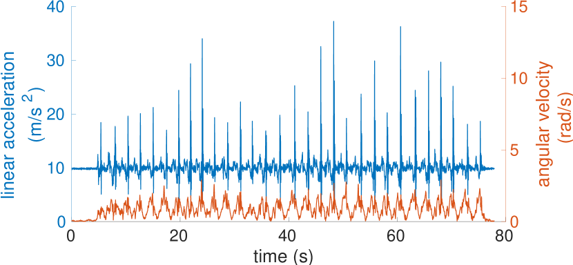
We first conducted an experiment to demonstrate the benefits of our wide FoV multi-camera setup. Using our wearable device attached to the thigh of a human operator, we collected one sequence consisting of level ground walking at a normal speed to mimic the exoskeleton walking pattern. We reported maximum linear accelerations of , and angular velocity up to , as shown in Fig. 3. We recorded both wide and narrow FoV images and used a Vicon motion capture system to provide ground truth poses.
For each camera setup, we ran VILENS-MC [22], a fixed-lag optimization-based odometry algorithm designed for multi-camera systems. The estimated trajectory from VILENS-MC was compared to the ground truth with alignment. We reported the of the as our main evaluation metric.
| Relative Pose Error (RPE) – Translation [m] / Rotation [°] | |||||||||
|---|---|---|---|---|---|---|---|---|---|
|
|
|
|
||||||
| 2 | Fail | Fail | |||||||
| 3 | 0.61 | 3.57 | |||||||
| 2 | 0.34 | 2.38 | |||||||
| 3 | 0.11 | 2.70 | |||||||
Tab. I reports the main results of this experiment. We observed that using a small FoV camera results in significant drift or even motion tracking failure due to the high accelerations and jerks present in the walking motion. Wider FoV cameras help to mitigate these effects, significantly reducing drift. Adding the lateral camera mitigates situations where no features are detected in the front of the device. The lowest drift rates were achieved using both wide FoV cameras and a multi-camera setup, providing front and lateral views. This combination achieves reliable motion tracking, even in scenarios with significant viewpoint changes or occlusions under the jerky walking motion.
It is also worth noting that even for the best performing configuration, VILENS-MC still exhibited a drift rate. However, typical drift rates of have been reported for smoothly moving handheld devices or mobile robot scenarios [22]. This suggest that further improvements can be achieved in this domain.
To demonstrate the generality of the benefits of applying wide FoV multi-camera system on state estimator and select the most appropriate one for our pipeline, we therefore conducted an odometry comparison shown in Sec. IV-B.
IV-B Comparison of Visual-Inertial Odometry Algorithms
We compared VILENS-MC to two other state estimation algorithms: ORB-SLAM (optimization-based) and OpenVINS (filtering-based) using our wide FoV multi-camera setup. In our experiments we used the stereo-inertial configuration of ORB-SLAM as it does not support multi-camera setups; we also disabled the loop closures mechanisms for a fair comparison with the odometry systems. For OpenVINS and VILENS-MC, we used a multi-camera setup: OpenVINS processes each camera as a monocular input, while VILENS-MC treats the three cameras as a stereo pair and a monocular camera.
We collected two short sequences, named seq01 and seq02 and adopted the same evaluation strategy as Sec. IV-A. In seq01, the operator walked at a slow place in a loop that included a small staircase. The sequence had a peak linear acceleration of and rotation rate of . In seq02 we included periods of abrupt rotation change and occasional occlusions of the front stereo cameras. This sequence had peak acceleration and rotation rates of and respectively. The algorithms were run five times on each sequence. at and are presented in Tab. II.
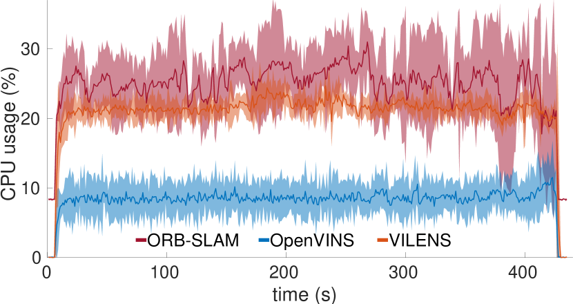
Additionally, to provide further insights on the computational budget required by each method, we logged the CPU usage of the algorithms on a larger scale indoor sequence. These results are presented in Fig. 4.
| Relative Pose Error (RPE) – Translation [m] / Rotation [°] | |||||
|---|---|---|---|---|---|
| Dist | Method | seq01 | seq02 | ||
| Translation | Rotation | Translation | Rotation | ||
| 1m | ORB-SLAM | 0.08 | 3.14 | 0.19 | 2.49 |
| OpenVINS | 0.06 | 3.45 | 0.15 | 2.55 | |
| VILENS-MC | 0.10 | 3.62 | 0.14 | 2.55 | |
| 5m | ORB-SLAM | 0.27 | 3.62 | 0.58 | 3.56 |
| OpenVINS | 0.20 | 3.40 | 0.40 | 4.10 | |
| VILENS-MC | 0.26 | 3.20 | 0.38 | 4.25 | |
Our odometry evaluation metrics showed that the selected VIO algorithms are robust and reliable even during walking patterns. We observed that the use of wide FoV cameras in our hardware design mitigated the main challenges of the application. Additionally, in the more challenging sequence (seq02), ORB-SLAM experienced a higher drift due to the lack of multi-camera support, a finding corroborated by previous research [22].
As a result, we chose OpenVINS as the VIO method for the system pipeline (Fig. 2). The reasons are twofold: First, it demonstrated relatively low translational error in RPE for both sequences, while achieving equivalent performance in orientation estimation. Second, it demonstrated lower CPU computation, as illustrated in Fig.4, which spares more resources for the later mapping module in the system pipeline.
IV-C Evaluation on Multi-floor Semantic Terrain Reconstruction
We next evaluated the terrain reconstruction quality on two custom real-world sequences, using the same sensing device introduced in Sec. III-A:
-
•
Office [m, 5 rooms, 2 floors] is a dataset collected at the Oxford Robotics Institute, including offices, staircases and a kitchen.
-
•
Home [m, 6 rooms, 3 floors] is a dataset collected in a multi-story house, with a living room, kitchen, bedrooms and bathrooms.
To determine the ground truth in the multi-floor buildings, we first built a highly accurate 3D model using a LIDAR-based SLAM system [31]. We placed a set of AprilTags [32] which the Exosense’s camera could detect. This allowed us to precisely localize the device, obtaining a sparse ground truth trajectory of the device around the building.
| Absolute Trajectory Error (ATE) – Translation [m] / Rotation [°] | ||||||
|---|---|---|---|---|---|---|
| Sequence |
|
|
|
|||
| Office | 145 | 0.11 | 3.34 | |||
| Home | 191 | 0.10 | 4.87 | |||
Our objective was to demonstrate and evaluate the geometric and semantic reconstruction capabilities of Exosense across different floors. We used OpenVINS as the odometry estimator, and LEXIS as the pose graph SLAM system. We compared the trajectory estimated by LEXIS against the sparse ground truth trajectory from AprilTags, and we reported the for both sequences, shown in Tab. III. Our results were similar to the numbers reported in LEXIS [26], which were obtained using a handheld device, validating the design decisions on the hardware and state estimator.
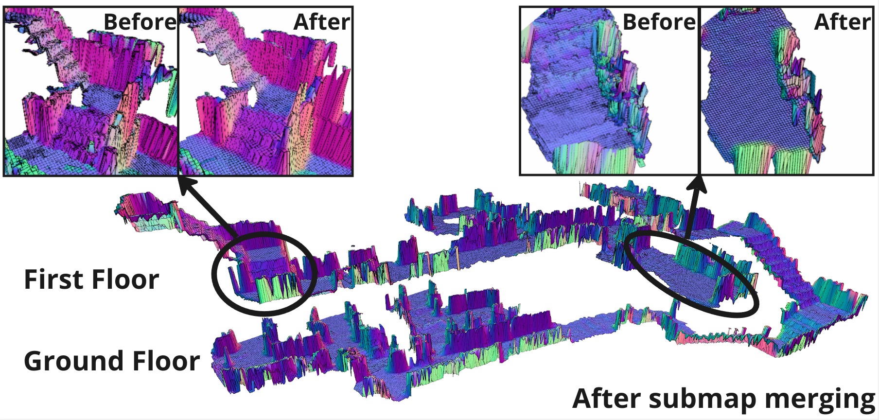
Regarding the reconstruction quality, Fig. 5 shows a qualitative example of the reconstruction of the Office sequence. The visualization depicts the reconstructed area colored by normals, both before and after applying the intra-room submap fusion strategy introduced in Sec. III-D. One can see substantial improvement of terrain flatness post-fusion, along with improved crispness at the edges of the staircase steps. Our fusion strategy can mitigate outliers present in the individual submaps, resulting in a consistent reconstruction of each room.
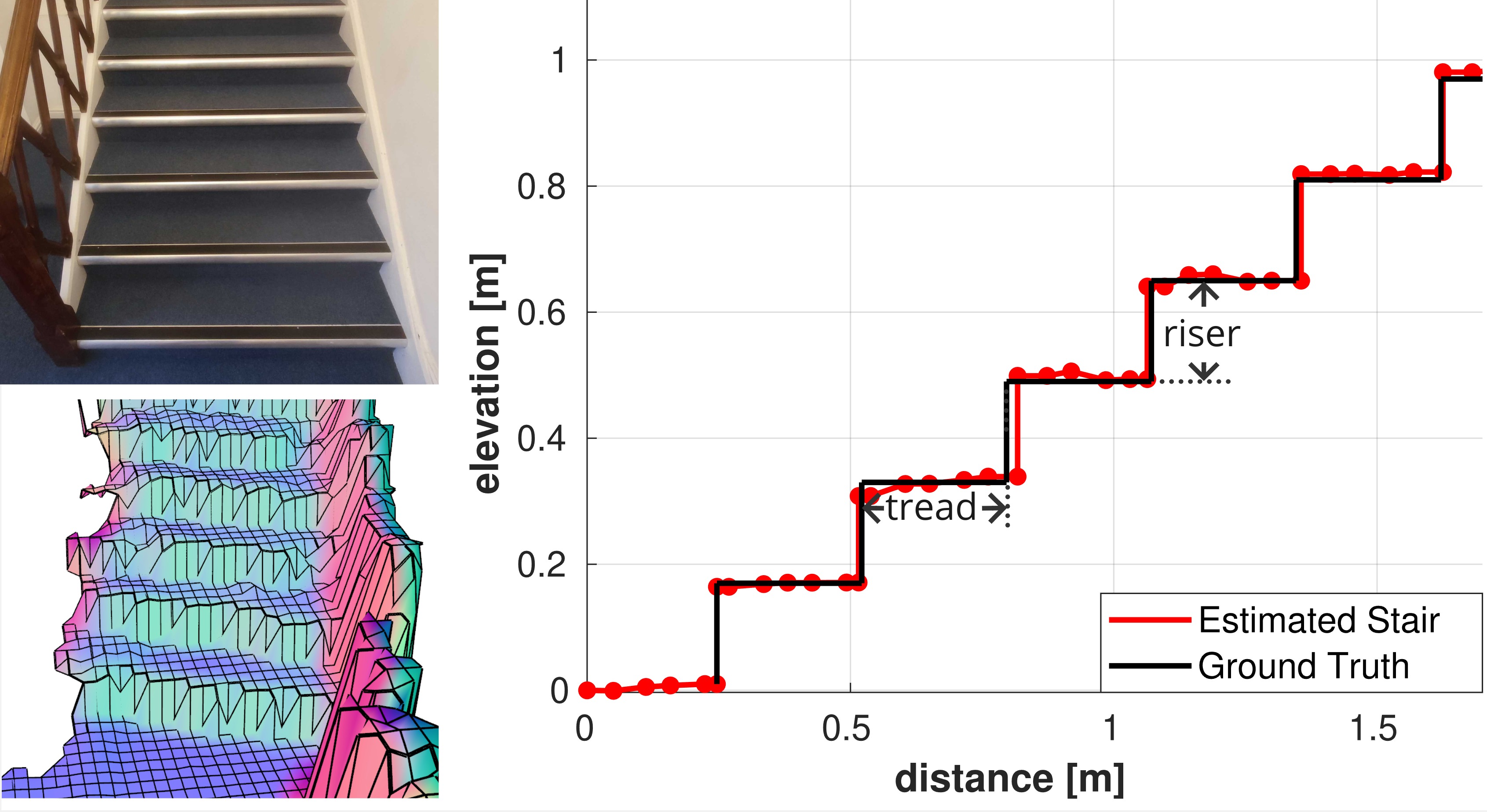
Furthermore, we evaluated the reconstruction quality in critical and challenging areas for exoskeleton locomotion, such as staircases. This involved manual measurement of the riser height (vertical surface) and tread depth (horizontal area) of staircase steps in both sequences to derive a parametric model of the staircase profile. Subsequently, we compared the riser and tread values obtained from our reconstruction with those from the ideal model, measuring the average error, as depicted in Fig. 6. Tab. IV presents the reconstruction error obtained for both the Office and Home sequences, demonstrating consistent reconstruction of the staircase.
| Staircase Parameters | |||||
|---|---|---|---|---|---|
| mean [cm] | st. dev. [cm] | gt [cm] | error [%] | ||
| Office | Tread Depth | 27.8 | 2.6 | 29 | 4.1 |
| Riser Height | 16.1 | 8.0 | 15 | 7.3 | |
| Home | Tread Depth | 19.7 | 1.3 | 19 | 3.6 |
| Riser Height | 19.8 | 3.3 | 21 | 5.7 | |
IV-D Evaluation on Terrain Traversability Analysis
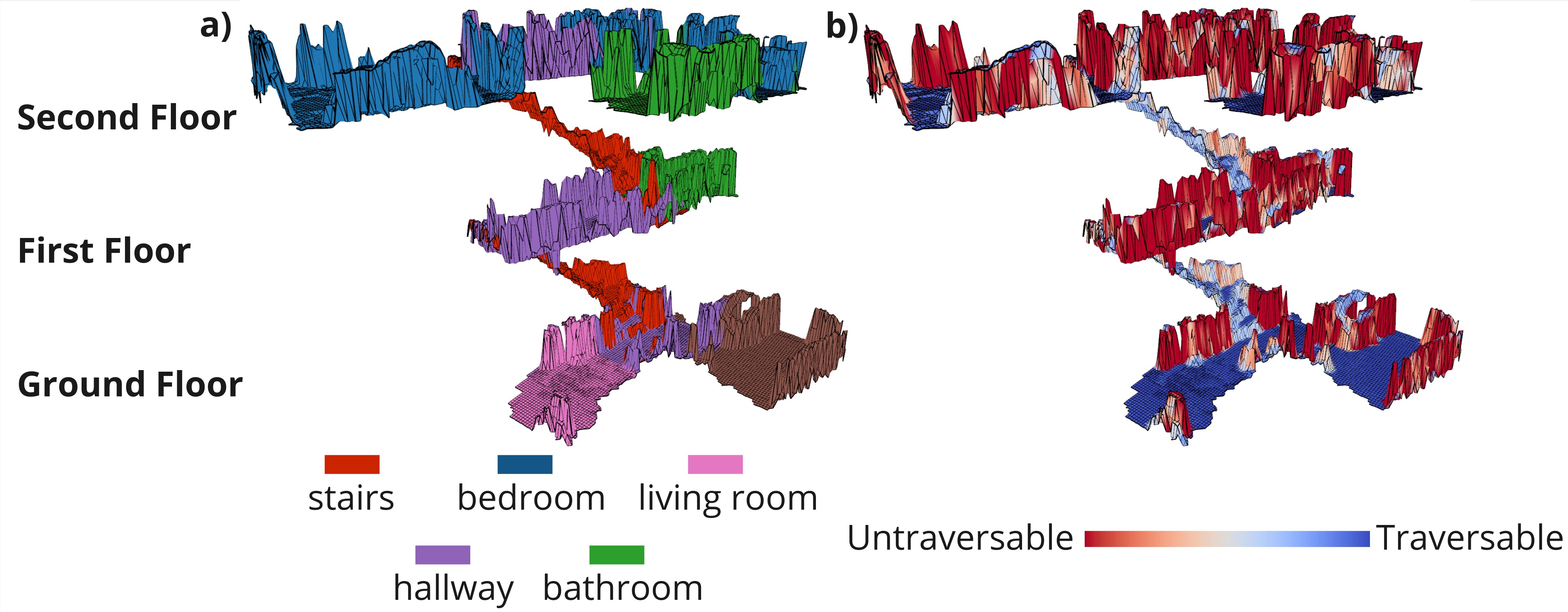
Next, we assessed the proposed semantic room segmentation and traversability estimation approaches for the Office and Home sequences. Fig. LABEL:fig:cover and 7 illustrate the global reconstruction results with semantic labels and the estimated traversability scores. We observed that the room labels from LEXIS can accurately annotate the submaps corresponding to each room, ensuring a coherent semantic map. Nevertheless, we observed labeling issues in room transitions such as doorways or staircase terminations, this will be further investigated in future work.
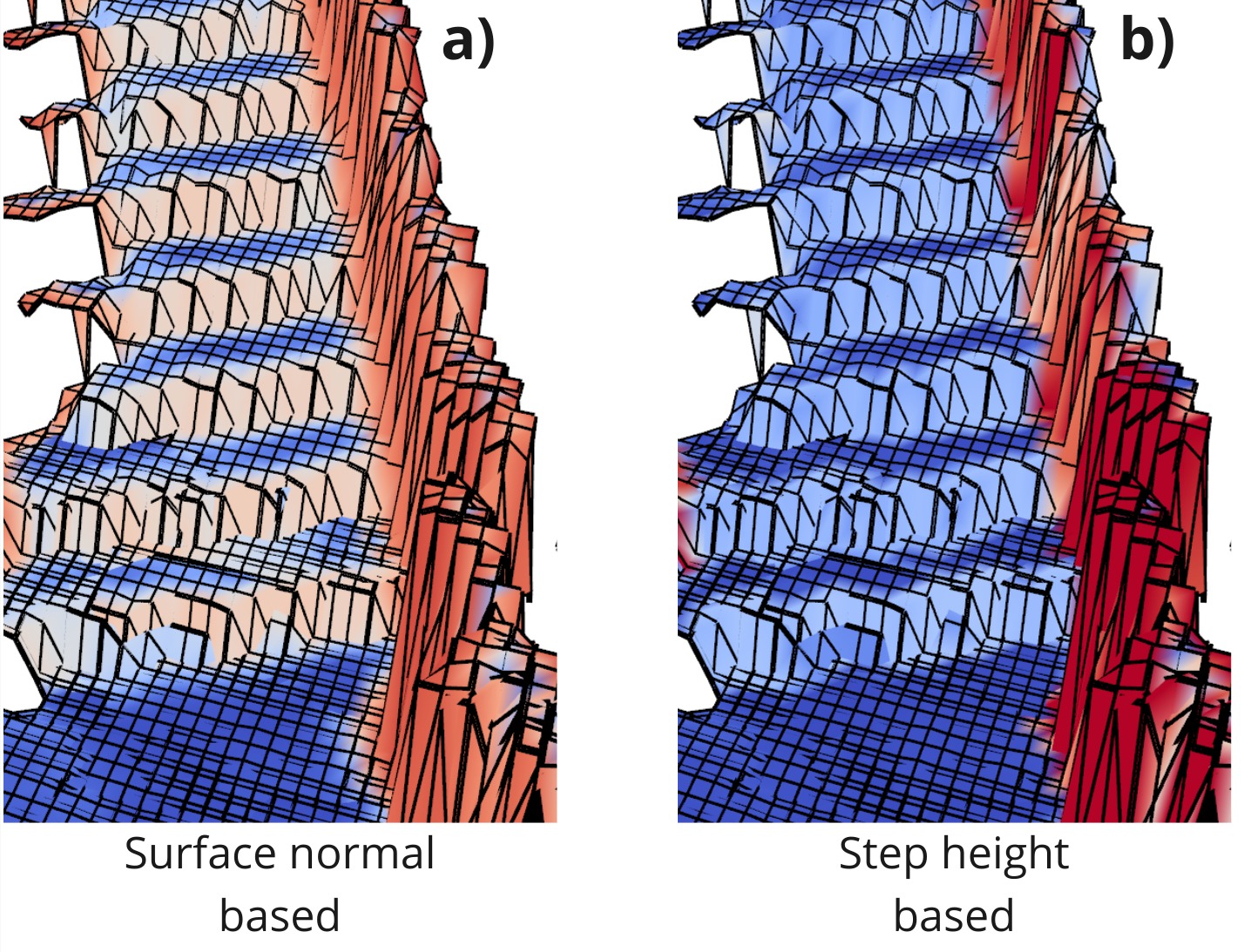
In Fig. 8, we present an example of our proposed traversability score and compare it to alternative geometric methods based on surface normals [33]. In challenging areas for locomotion, specifically staircases, our method uses a set of nominal walking parameters to determine a sensible estimate of the traversable areas. It correctly assigned high traversability scores to the riser and treads of the staircase, which reflects the effective traversable areas of a walking system. In contrast, methods based on normals (but not heights) correctly determined walls to be untraversable, but may assign low traversability scores to the risers—which is undesired for navigation tasks.
V Hierarchical Planning Demonstration
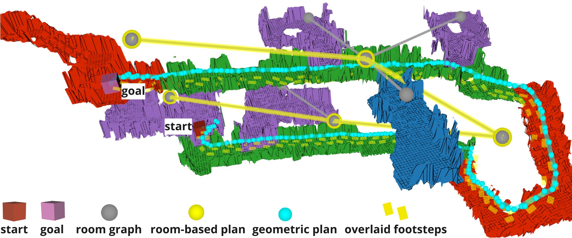
We finally demonstrate a hierarchical motion planning application as one of the downstream tasks that can be achieved using the representation produced by the Exosense system. We implemented a hierarchical planner to showcase room-to-room navigation. The method was based on two stages: room-level planning and geometric motion planning. In the room-level planning stage, we built a room graph from LEXIS’ output, which encoded the connectivity of the rooms. This enabled us to simply use Dijkstra’s algorithm [34] to find a sequences of rooms to reach the goal. For geometric planning, we computed a probabilistic roadmap (PRM) [35] for each room, using the step-based traversability score. Then, using the sequence of rooms, we could execute multi-query planning across different rooms by first determining the sequence of rooms, and then querying the PRM to find a valid geometric path.
Fig. 9 shows an instance of the plans that could be obtained with this hierarchical approach, suggesting potential applications that our representation offers for exoskeleton navigation in multi-story buildings.
VI Conclusions
In this work we presented Exosense, an integrated vision-based system for scene understanding. Our work studied both the hardware and systems required to build consistent, semantic representations of multi-story buildings. Particularly, we studied different camera setups, confirming that wide FoV multi-camera setups are capable of maintaining accurate motion tracking despite the highly dynamic walking pattern of an exoskeleton, suggesting that the achievable performance is agnostic to the choice of the state estimation algorithm. Further, we demonstrated a complete indoor mapping pipeline, that leveraged VLM-based SLAM for semantic scene understanding, as well as gait-specific traversability analysis to enable consistent navigation in indoor scenes. We demonstrated how our system can enable high-level planning tasks on the output map, thereby potentially providing safe navigation capabilities for exoskeleton devices. In future work we consider extending the VLM aspects of our system to assist the planning approach with natural language, as well as extending the applicability of Exosense for long-term, multi-session localization and mapping scenarios.
ACKNOWLEDGMENT
This work is supported in part by a Royal Society University Research Fellowship (Fallon, Kassab), and the ANID/BECAS CHILE/2019-72200291 (Mattamala). We also thank Wayne Tubby for hardware design support, and Wandercraft for initial inputs on the project.
References
- [1] T. Gurriet, S. Finet, G. Boeris, A. Duburcq, A. Hereid, O. Harib, M. Masselin, J. Grizzle, and A. D. Ames, “Towards restoring locomotion for paraplegics: Realizing dynamically stable walking on exoskeletons,” in IEEE Int. Conf. Robot. Autom. (ICRA), 2018, pp. 2804–2811.
- [2] T. Yan, M. Cempini, C. M. Oddo, and N. Vitiello, “Review of assistive strategies in powered lower-limb orthoses and exoskeletons,” Robot. Auton. Syst., vol. 64, pp. 120–136, 2015.
- [3] A. G. Kurbis, B. Laschowski, and A. Mihailidis, “Stair recognition for robotic exoskeleton control using computer vision and deep learning,” in International Conference on Rehabilitation Robotics (ICORR), 2022, pp. 1–6.
- [4] K. Karacan, J. T. Meyer, H. I. Bozma, R. Gassert, and E. Samur, “An environment recognition and parameterization system for shared-control of a powered lower-limb exoskeleton,” in IEEE RAS EMBS Int. Conf. Biomed. Robot. Biomechatronics, 2020, pp. 623–628.
- [5] A. H. A. Al-Dabbagh and R. Ronsse, “Depth vision-based terrain detection algorithm during human locomotion,” IEEE Transactions on Medical Robotics and Bionics, vol. 4, no. 4, pp. 1010–1021, 2022.
- [6] D.-X. Liu, J. Xu, C. Chen, X. Long, D. Tao, and X. Wu, “Vision-assisted autonomous lower-limb exoskeleton robot,” IEEE Trans. Syst. Man Cybern. Syst., vol. 51, no. 6, pp. 3759–3770, 2021.
- [7] N. Hughes, Y. Chang, and L. Carlone, “Hydra: A Real-time Spatial Perception System for 3D Scene Graph Construction and Optimization,” in Robotics: Science and Systems (RSS), 2022.
- [8] M. Ramanathan, L. Luo, J. K. Er, M. J. Foo, C. H. Chiam, L. Li, W. Y. Yau, and W. T. Ang, “Visual environment perception for obstacle detection and crossing of lower-limb exoskeletons,” in IEEE/RSJ Int. Conf. Intell. Robots Syst. (IROS), 2022, pp. 12 267–12 274.
- [9] W. Bao, D. Villarreal, and J.-C. Chiao, “Vision-based autonomous walking in a lower-limb powered exoskeleton,” in IEEE 20th International Conference on Bioinformatics and Bioengineering (BIBE), 2020, pp. 830–834.
- [10] A. Hornung, K. M. Wurm, M. Bennewitz, C. Stachniss, and W. Burgard, “Octomap: An efficient probabilistic 3d mapping framework based on octrees,” Autonomous Robots, vol. 34, pp. 189–206, 2013.
- [11] P. Fankhauser, M. Bloesch, and M. Hutter, “Probabilistic terrain mapping for mobile robots with uncertain localization,” IEEE Robot. Autom. Lett. (RA-L), vol. 3, no. 4, pp. 3019–3026, 2018.
- [12] S. Kuindersma, R. Deits, M. F. Fallon, A. Valenzuela, H. Dai, F. Permenter, T. Koolen, P. Marion, and R. Tedrake, “Optimization-based locomotion planning, estimation, and control design for the atlas humanoid robot,” Autonomous Robots, vol. 40, no. 3, pp. 429–455, 2016.
- [13] D. D. Fan, K. Otsu, Y. Kubo, A. Dixit, J. Burdick, and A. Agha-mohammadi, “STEP: stochastic traversability evaluation and planning for risk-aware off-road navigation,” in Robotics: Science and Systems (RSS), 2021.
- [14] X. Meng, N. Hatch, A. Lambert, A. Li, N. Wagener, M. Schmittle, J. Lee, W. Yuan, Z. Q. Chen, S. Deng, G. Okopal, D. Fox, B. Boots, and A. Shaban, “Terrainnet: Visual modeling of complex terrain for high-speed, off-road navigation,” in Robotics: Science and Systems (RSS), 2023.
- [15] T. Miki, L. Wellhausen, R. Grandia, F. Jenelten, T. Homberger, and M. Hutter, “Elevation mapping for locomotion and navigation using gpu,” in IEEE/RSJ Int. Conf. Intell. Robots Syst. (IROS), 2022, pp. 2273–2280.
- [16] G. Erni, J. Frey, T. Miki, M. Mattamala, and M. Hutter, “MEM: multi-modal elevation mapping for robotics and learning,” in IEEE/RSJ Int. Conf. Intell. Robots Syst. (IROS), 2023, pp. 11 011–11 018.
- [17] P. Ewen, A. Li, Y. Chen, S. Hong, and R. Vasudevan, “These maps are made for walking: Real-time terrain property estimation for mobile robots,” IEEE Robot. Autom. Lett. (RA-L), vol. 7, no. 3, pp. 7083–7090, 2022.
- [18] H. Bavle, J. L. Sanchez-Lopez, M. Shaheer, J. Civera, and H. Voos, “S-Graphs+: Real-Time Localization and Mapping Leveraging Hierarchical Representations,” IEEE Robot. Autom. Lett. (RA-L), vol. 8, no. 8, pp. 4927–4934, 2023.
- [19] S. Peng, K. Genova, C. M. Jiang, A. Tagliasacchi, M. Pollefeys, and T. Funkhouser, “OpenScene: 3D Scene Understanding with Open Vocabularies,” in IEEE Int. Conf. Computer Vision and Pattern Recognition (CVPR), 2023.
- [20] J. Kerr, C. M. Kim, K. Goldberg, A. Kanazawa, and M. Tancik, “LERF: Language Embedded Radiance Fields,” in Intl. Conf. on Computer Vision (ICCV), 2023.
- [21] N. M. M. Shafiullah, C. Paxton, L. Pinto, S. Chintala, and A. Szlam, “CLIP-Fields: Weakly Supervised Semantic Fields for Robotic Memory,” in Robotics: Science and Systems (RSS), 2023.
- [22] L. Zhang, D. Wisth, M. Camurri, and M. Fallon, “Balancing the budget: Feature selection and tracking for multi-camera visual-inertial odometry,” IEEE Robot. Autom. Lett. (RA-L), vol. 7, no. 2, pp. 1182–1189, 2022.
- [23] Z. Zhang, H. Rebecq, C. Forster, and D. Scaramuzza, “Benefit of large field-of-view cameras for visual odometry,” in IEEE Int. Conf. Robot. Autom. (ICRA), 2016, pp. 801–808.
- [24] P. Geneva, K. Eckenhoff, W. Lee, Y. Yang, and G. Huang, “Openvins: A research platform for visual-inertial estimation,” in IEEE Int. Conf. Robot. Autom. (ICRA), 2020, pp. 4666–4672.
- [25] C. Campos, R. Elvira, J. J. Gomez, J. M. M. Montiel, and J. D. Tardos, “ORB-SLAM3: An accurate open-source library for visual, visual-inertial and multi-map SLAM,” IEEE Trans. Robotics, vol. 37, no. 6, pp. 1874–1890, 2021.
- [26] C. Kassab, M. Mattamala, L. Zhang, and M. Fallon, “Language-EXtended Indoor SLAM (LEXIS): A Versatile System for Real-time Visual Scene Understanding,” in IEEE Int. Conf. Robot. Autom. (ICRA), 2024.
- [27] A. Radford, J. W. Kim, C. Hallacy, A. Ramesh, G. Goh, S. Agarwal, G. Sastry, A. Askell, P. Mishkin, J. Clark, G. Krueger, and I. Sutskever, “Learning transferable visual models from natural language supervision,” in Intl. Conf. on Machine Learning (ICML), 2021.
- [28] M. A. Fischler and R. C. Bolles, “Random Sample Consensus: A Paradigm for Model Fitting with Applications to Image Analysis and Automated Cartography,” Commun. ACM, vol. 24, no. 6, p. 381–395, 1981.
- [29] M. Bosse, P. M. Newman, J. J. Leonard, and S. J. Teller, “Simultaneous localization and map building in large-scale cyclic environments using the atlas framework,” Intl. J. of Robot. Res., vol. 23, no. 12, pp. 1113–1139, 2004.
- [30] P. Fankhauser and M. Hutter, “A Universal Grid Map Library: Implementation and Use Case for Rough Terrain Navigation,” in Robot Operating System (ROS) – The Complete Reference (Volume 1), A. Koubaa, Ed. Springer, 2016, ch. 5.
- [31] M. Ramezani, G. Tinchev, E. Iuganov, and M. Fallon, “Online lidar-slam for legged robots with robust registration and deep-learned loop closure,” in IEEE Int. Conf. Robot. Autom. (ICRA). IEEE, 2020, pp. 4158–4164.
- [32] E. Olson, “AprilTag: A robust and flexible visual fiducial system,” in IEEE Int. Conf. Robot. Autom. (ICRA). IEEE, May 2011, pp. 3400–3407.
- [33] M. Wermelinger, P. Fankhauser, R. Diethelm, P. Krüsi, R. Siegwart, and M. Hutter, “Navigation planning for legged robots in challenging terrain,” in IEEE/RSJ Int. Conf. Intell. Robots Syst. (IROS), 2016, pp. 1184–1189.
- [34] E. W. Dijkstra, “A note on two problems in connexion with graphs,” Numerische mathematik, vol. 1, no. 1, pp. 269–271, 1959.
- [35] L. Kavraki, P. Svestka, J.-C. Latombe, and M. Overmars, “Probabilistic roadmaps for path planning in high-dimensional configuration spaces,” IEEE Trans. Robotics and Automation, vol. 12, no. 4, pp. 566–580, 1996.