†Corresponding author: zscnum1@126.com, zscgroup@kmust.edu.cn
2-D isotropic negative refractive index in a N-type four-level atomic system
Abstract
2-D(Two-dimensional) isotropic negative refractive index (NRI) is explicitly
realized via the orthogonal signal and coupling standing-wave fields coupling
the N-type four-level atomic system. Under some key parameters of the dense
vapor media, the atomic system exhibits isotropic NRI with simultaneous
negative permittivity and permeability (i.e. Left-handedness) in the 2-D x-y plane.
Compared with other 2-D NRI schemes, the coherent atomic vapor media in our scheme
may be an ideal 2-D isotropic NRI candidate and has some potential
advantages, significance or applications in the further investigation.
Keywords: 2-D; isotropic negative refractive index; left-handedness
PACS: 42.50.Gy; 32.80.Qk; 32.10.Dk; 78.20.Ci
I Introduction
J.B. Pendry, et al. asserted that a medium with negative effective permeability can be achieved by the split-ring resonator (SRR) in free space1 , which has been studied to increase the permeability of artificial dielectrics in the 1952s2 . Smith et al. combined the SRR with thin wires to design the NRI medium in 20003 . And a year later, this SRR/wire composite medium was implemented and experimentally verified negative refraction for the first time4 . The implementation has given rise to the NRI media because of its exotic properties. In particular, the possible sub-wavelength resolving properties1 have stirred much excitement and renewed interest in electromagnetic phenomena associated with NRI medium, first investigated by Veselago in the 1960s5 .
With the development of investigating the NRI media, the requirement of 2-D NRI media is emerging. And several schemes6 ; 7 ; 8 ; 9 ; 10 ; 11 for 2-D NRI media have been proposed recently. However, most of the proposed 2-D NRI media are based on photonic crystal nanostructure or transmission line structure, and most of them are anisotropic, i.e., their exotic properties are polarization dependent, which is undesirable in certain potential applications, e.g., in “perfect lens”1 . As an alternative, the arbitrary linear incident polarization via the printable NRI media have been proposed by C. Imhof et al..12 .
Here, we first explore the possibility of implementing 2-D NRI media by using the quantum coherence effect in a four-level atomic system, which is driven by the orthogonal signal and coupling standing-wave fields. Thus, we can explicitly investigate the left-handedness and NRI of the resonant atomic system in the x-y plane. A few specific NRI values exhibit circular and homogeneous distributions in the x-y plane, and the atomic system possesses negative permittivity and permeability simultaneously.
II Model and equation
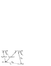
Consider a N-type four-level atomic system with two lower states and , two excited states and , which interacts with three optical fields, i.e., the weak probe light and two strong coherent coupling standing-wave fields , , respectively [see Fig.1]. Levels and have the same parity and level , with an opposite parity. Thus the electric and magnetic components of the weak probe light field couple the electric-dipole transition - and the magnetic-dipole transition -, respectively. Such the atomic system may be realized in (I=1/2). The states , , and correspond to , F=1/2,=-1/2, ,F=1/2, =1/2, , F=1/2, =-1/2 and , F=1/2, =1/2, respectively.
The Rabi frequencies corresponding to the two orthogonal standing-wave fields are ==, ==, respectively. , are the electric field strength envelopes of the two orthogonal standing-wave fields. =, (i = 1, 2) is the wave vector with wavelengths , (i= 1, 2) of the corresponding standing wave fields. And the two orthogonal signal and coupling standing-wave fields drive the transitions - and-, respectively. The frequency detunings of these three optical fields are , and , respectively. At a low temperature, the atoms are assumed to be nearly stationary and hence any Doppler shift is neglected. Under the rotating-wave approximations the equations of motion for the probability amplitudes of the atomic system in the x-y plane are given as follows,
where the electric and magnetic Rabi frequencies of the probe light are defined by , , respectively. Here, and denote the electric and magnetic field strength envelopes of the probe light. The frequency detunings are defined by =, =, and =. Where , and are the mode frequencies of the probe and two orthogonal standing-wave fields. and in Eq.(1) denote the spontaneous decay rates and the dephasing rate, respectively.
When the intensity of the probe light is sufficiently weak and the temperature is very low, all the atoms remain in the ground state and the atomic population in level is close to unity13 without any Doppler shift. Under these conditions, the steady solutions of Eq. (1) take the following forms
with the parameter
In the following, we consider the electric and magnetic responses of the N-type four-level atomic system interacting with two orthogonal stand-wave light fields.
Considering the distinction between the applied fields and the microscopic local fields acting upon the atoms when discussing the detailed properties of the atomic transitions between the levels relating to the electric and magnetic susceptibilities, there is little difference between the macroscopic fields and the local fields14 ; 17 in the dilute vapor case. However, the polarization of neighboring atoms gives rise to an internal field at any given atom in addition to the average macroscopic field. In order to achieve the negative permittivity and permeability one should consider the local field effect in dense media with closely packed atom.
We first obtain the atomic electric and magnetic polarizabilities, and then consider the local field correction to the electric and magnetic susceptibilities of the coherent vapor medium. Using the definitions of atomic microscopic electric and magnetic polarizabilities14 ; 15 , we can arrive at the following parameters
| (3) | |||||
| (4) | |||||
In the above calculations, = , = and the relation between the microscopic local electric and magnetic fields = has been inserted.
We have obtained the microscopic physical quantities . However, what we are interested in is the macroscopic physical quantities such as the electric permittivity and magnetic permeability. According to both the electric and magnetic Clausius-Mossotti relations14 ; 15 , we can arrive at the relative electric permittivity and magnetic permeability as follows
where N denotes the atomic concentration.
III Results and discussions
Here we will demonstrate the 2-D isotropic NRI can truly arise in the four-level coherent atomic vapor media interacting with two orthogonal standing-wave fields in the x-y plane. And the strong electric and magnetic responses can bring about simultaneously negative permittivity and permeability. For the sake of more closing to reality, several key parameters are adopted from the form investigation. The parameters for the atomic electric and magnetic polarizability are chosen as: the electric and magnetic transition dipole moments = and 16 , respectively. The density of atom N was chosen to be 17 . And the other parameters are scaled by : , . Because the dephasing rate is in general two or three orders of magnitude less than the spontaneous decay rates in a low-temperature vapor 18 , the dephasing rate is small and set to be .
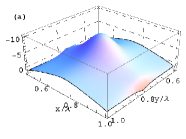
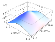
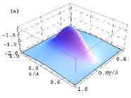
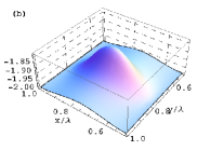
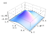
Then the three-dimensional plots depict the real part of relative permittivity , permeability and refraction index of the atomic system dependent the probe detuning as a function of (x, y), which are shown in Figs.2, 3 and 4, respectively. As shown in Fig.2, the real part of relative permittivity has the negative value in the x-y plane and the spike-like peak at the coordinate in Fig.2(a), Fig.2(b), Fig.2(c), Fig.2(d), respectively. We also noted remains the negative values with the decreasing peaks when the values of are tuned to be , and , in Fig.2(b), Fig.2(c), Fig.2(d), respectively.
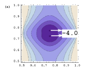
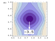
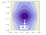
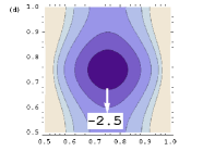
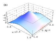
Fig.3 shows the the three-dimensional plots for the . It can be seen from Fig.3 that has negative values under the same condition as Fig.2. As shown in Fig.3 from (a) to (d), the increasing peak values of are observed when was tuned to be , , and , in spite of the weaker magnetic response than the electric response in Fig.2. What’s more, we note that alone the x axis the distribution pattern of shows the evolution of fin-like gradually into spike-like. Then an increasing magnetic response is shown when was gradually tuned increasingly. The simultaneously negative permittivity and permeability shown by Fig.2 and Fig.3 prove the 2-D left-handedness in the N-type four-level atomic system.
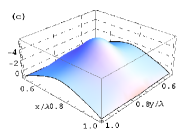
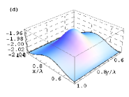
However, what interested us most is the value and distribution of refractive index in the x-y plane. Fig.4 gives the contour plots for the real part of refractive index in the x-y plane. The values indicated by the white arrows and distributions of the innermost contour lines corresponding to attract our intention mostly. Two points are the innermost contour diagram in Fig.4(a), and they get the value being -4.0 for with their corresponding coordinates and . The innermost contour line changes into one circle with its central coordinate in Fig.4(b), and the corresponding value of is -3.5. When is tuned by and , the innermost contour lines are still homogeneous and isotropic circles with the same centre coordinate in Fig.4(c) and Fig.4(d), respectively. And the values of corresponding to the innermost contour lines are -3.0, -2.5 in Fig.4(c) and Fig.4(d), respectively. The circle distributions with same centre coordinates in Fig.4(b),(c) and (d) manifest that can have the same value in all directions. That’s to say, is homogeneous and isotropic in the x-y plane when gets the following values,-3.5, -3.0, -2.5. The coherent N-type four-level atomic system can be a left-handed media with isotropic NRI when it gets the above mentioned values in the x-y plane.
IV Conclusion
We suggested a new scenario for 2-D isotropic NRI via two orthogonal standing-wave fields coupling two different atomic transitions in the N-type atomic system. In the x-y plane the simultaneously negative permittivity and permeability exhibit, which means the left-handedness in the N-type atomic system. What’s more, =-3.5, -3.0, -2.5 are both homogeneous and isotropic in the x-y plane in the same frequency band. Our scheme proposes a new scenario of 2-D isotropic NRI which may give an impetus to some potential advantages or applications. The proposed 2-D isotropic NRI media in our scheme should be paid more attention from both theoretically and experimentally in the near future.
References
- (1) J.B. Pendry, A. J. Holden, D. J. Robbins, and W. J. Stewart, “Magnetism From Conductors and Enhanced Nonlinear Phenomena,” IEEE Trans. Microwave Theory Tech., 47, 2075 (1999).
- (2) S. A. Schelkunoff and H.T. Friis, Antennas: Theory and Practice (John Wiley and Sons, New York), 1952
- (3) D. R. Smith, W. J. Padilla, D. C. Vier, S. C. Nemat-Nasser, and S. Schultz, “Composite Medium with Simultaneously Negative Permeability and Permittivity,” Phys. Rev. Lett., 84, 4184 (2000).
- (4) R. A. Shelby, D. R. Smith, and S. Schultz, “Experimental Verification of a Negative Index of Refraction,” Science, 292, 77 (2001).
- (5) V. G. Veselago,“The electrodynamics of substances with simultaneously negative values of and ,” Sov. Phys. Usp., 10, 509 (1968).
- (6) E. Cubukcu, “Negative refraction by photonic crystals,” Nature 423, 604 (2003).
- (7) A. Grbic and G. V. Eleftheriades, “Periodic Analysis of a 2-D Negative Refractive Index Transmission Line Structure,”IEEE transactions on antennas and propagation 51, 2604 (2003).
- (8) R. Mindy, R. Lee and P. M. Fauchet, “Two-dimensional silicon photonic crystal based biosensing platform for protein detection,”Opt. Exp. 15, 4530 (2007).
- (9) D. Dorfner, T. Hrlimann, T. Zabel, G. Abstreiter, L. H. Frandsen and J. Finley, “Silicon photonic crystal nanostructures for refractive index sensing,” Appl. Phys. Lett. 93 181103 (2008).
- (10) T. Ueda, A. Lai and T. Itoh, “Demonstration of Negative Refraction in a Cutoff Parallel-Plate Waveguide Loaded With 2-D Square Lattice of Dielectric Resonators,” IEEE transactions on microwave theory and techniques 55 1280 (2007).
- (11) R. Islam, M. Zedler and G. V. Eleftheriades, “Modal Analysis and Wave Propagation in Finite 2D Transmission-Line Metamaterials,”IEEE transactions on antennas and propagation 59 5 (2011) .
- (12) C. Imhof and R. Zengerle, “Pairs of metallic crosses as a left-handed metamaterial with improved polarization properties,” Opt. Express, 14, 8257 (2006).
- (13) M. O. Scully and M. S. Zubairy, Quantum Optics (Cambridge: Cambridge Univ. Press) Chapt. 7, (1997)
- (14) J. D. Jackson, Classical Electrodynamics, 3rd Ed (New York: John Wiley Sons), Chap. 4, 159 (2001).
- (15) D. M. Cook, The Theory of the Electromagnetic Field (New Jersey:Prentice-Hall, Inc.) Chap. 11, (1975).
- (16) J. Q. Shen, J. Almlf, S. He, “Negative permeability in a -type three-level atomic vapor”Appl. Phys. A 87 (2007) 291.
- (17) M. . Oktel and . E. Mstecapllu, “Electromagnetically induced left-handedness in a dense gas of three-level atoms,” Phys. Rev. A 70, 053806 (2004 )
- (18) Y. Q. Li and M. Xiao, “Transient properties of an electromagnetically induced transparency in three-level atoms ,”Opt. Lett.20, 1489 (1995).