Principles and Optimization of
Reflective Intelligent Surface Assisted mmWave Systems
††thanks: L.-L. Yang is with the School of Electronics and Computer Science, University of Southampton, SO17 1BJ, UK. (E-mail: lly@ecs.soton.ac.uk). This document is a chapter in the book: L.-L. Yang, J. Shi, K.-T. Feng, L.-H. Shen, S.-H. Wu and T.-S. Lee, Resource Optimization in Wireless Communications: Fundamentals, Algorithms and Applications, Academic Press, USA (to be published in 2024).
Abstract
A conceptual example is first analyzed to show that efficient wireless communications is possible, when user equipment (UE) receiver, BS transmitter or/and the scatter (reflector) in wireless channels employ the required channel state information (CSI) to remove the randomness of signal phase. Then, the principles and optimization of three reflective intelligent surface (RIS) assisted mmWave (RIS-mmWave) models are introduced. The first model assumes one BS, one RIS and one UE; the second one assumes one BS, one RIS and multiple UEs; while the third RIS-mmWave model assumes one BS, multiple RISs and multiple UEs. Furthermore, the optimization of BS precoder and RIS phase-shifts is addressed in the context of the massive RIS-mmWave scenarios, where the number of BS antennas and that of RIS reflection elements are significantly larger than the number of supported UEs. The analyses demonstrate that, while the deployment of RISs with mmWave is capable of solving the blockage problem and has the potential to significantly improve efficiency, finding the near-optimum solutions for RIS phase-shifts is highly challenging in practice.
Index Terms:
Reflective intelligent surface (RIS), millimeter wave (mmWave), massive RIS-mmWave, massive MIMO, active RIS, passive RIS, optimization, transceiver optimization, precoder design, beamforming, RIS optimization, power-allocationI Introduction
Reflection and scattering always play important roles in wireless communications. When frequency is relatively low, a radio signal sent by a transmitter may be reflected/scattered many times by different objects distributed near or on the route from transmitter to receiver, making the received signal a linear combination of the signals come from different routes, named as propagation paths. When many signals by different propagation paths arrive at receiver at similar time, the central-limit theorem can be applied to explain their overall behavior, and the received signal can be modeled as a complex Gaussian random variable, generating the so-called Rayleigh fading, if there isn’t a line-of-sight (LoS) or dominate path between transmitter and receiver. Otherwise, if there is a dominate path from transmitter to receiver, the magnitude of received signal obeys the Rician distribution, yielding Rician fading [1, 2].
As the distances of the physical paths from a transmitter to a receiver are different, the received signals from different paths have different delays, yielding the concept of delay-spread accounting for the relative delay between the earliest and latest arrivals of a same transmitted signal. When the delay spread is comparable to the symbol duration, serious inter-symbol interference (ISI) may occur, if receiver chooses to ignore it. By contrast, if receiver makes an effort to resolve the received signal into several component signals with respect to the delay-spread, the component signals can be coherently combined to obtain diversity gain for performance improvement [3].
Similarly, when transmitter, receiver or/and reflectors/scatters are in moving, different physical paths may experience different Doppler-frequency shifts, giving the concept of Doppler-spread accounting for the frequency shifting range of a transmitted frequency resulted from the above-mentioned mobility. This phenomenon can make the orthogonally transmitted subcarrier signals become non-orthogonal, generating inter-carrier interference (ICI). Again, if receiver is capable of resolving the received signal into several component signals with respect to the Doppler-spread, the component signals can be jointly exploited to obtain diversity gain [4, 5].
In the conventional wireless communications operated in relatively low-frequency bands, wireless channels generated by numerous nature reflectors/scatters are uncontrollable. When wireless communications enters the mmWave and Terahertz eras, radio signals propagate more and more as visible lights, there are usually only a very few of rays (paths) from transmitter to receiver, with the LoS path carrying most of transmit power, which however has a not ignorable probability to be blocked. If LoS path is blocked, communication performance significantly degrades. To provide seamless services of similar performance, in this case, alternative propagation paths are needed. Reflective intelligent surfaces (RISs) [6, 7, 8] have been proposed for this purpose and, furthermore, for actively controlling radio propagation environments to improve the performance of wireless communications.
RISs can be classified as passive RISs [9] and active RISs [9]. A passive RIS is designed to be equipped with a large number of reflective elements, each of which is able to reflect the incident signal with a controllable phase shift, but is unable to control the amplitude of the incident signal. A passive RIS does not employ active radio-frequency components. Hence, it consumes near-zero direct-current (DC) power, and introduces near-zero thermal noise. In contrast, an active RIS element can reflect the incident signal with a modified phase shift, and also scale the amplitude of the reflected signal. Accordingly, the active processing may consume certain DC power, and also introduce some thermal noise.
In the above-mentioned passive and active RISs, a RIS element only reflects the signal impinging on itself. More advanced RISs may be designed to make a RIS element emit the signals received by the other reflection elements, in addition to reflecting the signals impinging on itself [10].
This chapter provides the principles of RIS and analyzes the optimization in RIS-mmWave systems. Specifically, in Section II, a conceptual example is analyzed to show the principles of information transmission in a wireless system, when receiver, transmitter or/and reflector employs CSI. Then, in Sections III-V, three RIS-mmWave system models are analyzed. Specifically, the first model in Section III assumes one BS, one RIS and one UE; the second one in Section IV assumes one BS, one RIS and multiple UEs; while the third RIS-mmWave model in Section V assumes one BS, multiple RISs and multiple UEs. Some challenges in the implementation of RISs are discussed in Section VI.
II A Conceptual Example
Following the historical development of wireless systems, in this subsection, a simple model as shown in Fig. 1 is analyzed to show the impact of reflectors on radio signal transmission and the possible opportunities provided for the design of wireless systems. As shown in Fig. 1, the model considers one transmitter, one receiver and two reflectors of sufficiently separated. There are three transmission paths from transmitter to receiver, one LoS path that may or may not be blocked, and two reflected paths. The model parameters and represent distances and heights, respectively. The objective of design is to maximize signal-to-noise ratio (SNR) at receiver, under the condition of the channel knowledge available to transmitter, reflectors, or/and receiver. Note that, SNR is considered because it is the reflection of reliability, and the spectral-efficiency of a communication scheme is a monotonically increasing function of SNR. Below several specific cases are addressed. Except the first and second ones considering LoS path, all the other cases assume that LoS path is blocked.
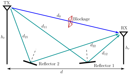
In the first case, we assume that there is only a LoS path between transmitter and receiver, which is separated by a distance . Then, when a radio signal , satisfying , sent by transmitter using power propagates over free-space, the received signal can be represented as
| (1) |
where is the complex Gaussian noise, assumed to be distributed with mean zero and variance per dimension, expressed as , and is a certain constant. For example, assume that the isotropic antenna is employed. Then, according to Friis formula for free-space propagation [3], we have , where and are gains of transmit and receive antennas, respectively, and is wavelength. In (1), is a phase resulted from LoS propagation, which is dependent on radio wave’s traveling distance and wavelength, given as [11]. From (1), the SNR at receiver can be expressed as
| (2) |
showing that the SNR for information detection decays with the square of distance .
The second case assumes that the received signal consists of the LoS path and one reflected path by ground, which has been considered in many textbooks on wireless channel modeling [11, 2, 12]. Also, we assume that neither transmitter nor receiver know that there are two paths. In this case, when is transmitted, the received signal can be expressed as
| (3) |
where is the reflection coefficient, with , as shown in Fig. 1. According to Fig. 1, geometrically, we can obtain , and . Assume that , and also . We have the approximations of and . Substituting these results into (3) yields
| (4) |
where is applied, and if we use . Now from (II), the received SNR is
| (5) |
showing that the received power decreases with the fourth power of the distance between transmitter and receiver. Note that, as the approximated is not dependent on frequency, the SNR of (5) is less dependent on frequency than (2).
In the third case, we assume that there is no LoS path, but there are two reflected paths from transmitter to receiver. We assume that transmitter has no channel knowledge, reflectors are incapable of doing anything except reflecting the incident signal, while receiver is unable to distinguish the two incoming rays. Then, the received signal can be represented as [2, 11]
| (6) |
where , , are reflection coefficient, , while is a function of and , which is dependent on the properties of reflector. For example, according to literature [11, 2, 12, 7, 13], when in near-field transmission and the size of reflectors is large with respect to transmission distance, is satisfied. In contrast, when in the far-field transmission where reflectors are small relative to transmission distance, making them approximately as points, we have .
Since receiver is unable to distinguish the individual paths, it has to treat them as one and view (6) in the form of
| (7) |
with
| (8) |
To execute signal detection, receiver first estimates in (7) and then carries out the detection after removing the effect of . The SNR of detection is
| (9) |
It shows that SNR is dependent on the difference between and , and hence fluctuates. In other words, the two paths are interfering waves, their sum can be constructive or destructive.
The fourth case uses the same assumptions as the third one, except that the receiver is now able to distinguish the two incoming paths and tracking the gains and phases of the two paths. In other words, the receiver can obtain two received signals as111No interference between two paths is assumed.
| (10) |
and is able to obtain the knowledge about and . Hence, it can implement the maximal ratio combining (MRC)[3] to maximize the receive SNR222Note that MRC is optimum to maximize SNR., generating the decision variable
| (11) |
Correspondingly, the receive SNR is
| (12) |
which is a constant. Hence, the achieved performance is stable for a given .
Note that, (II) explains that, to maximize receive SNR, the MRC enhances the stronger path and discourages the weaker path in the detection.
In the fifth case, the assumptions are the same as that of the third case, except that the transmitter now has the knowledge about the phases introduced by propagation, i.e., knows and . In this case, when assuming that transmitter is designed to be able to send and over Paths 1 and 2, respectively, the received signal can be expressed as
| (13) |
where infers that half of power is radiated on each of the two paths. Readily, the receive SNR in this case is
| (14) |
The sixth case is as the fifth case, but now the transmitter is more capable, which can acquire full knowledge about the propagation conditions, i.e., knows and . Then, to maximize the receive SNR, transmitter sends
| (15) |
via the th path. Accordingly, the received signal is
| (16) |
making the receive SNR be
| (17) |
It can be shown that this SNR is larger than that in (14), provided that .
In the last (seventh) case, the assumptions in the third case are applied, except that the reflectors are now capable of configuring their reflection coefficients. Specifically, when reflector is only able to control its reflected phase by multiplying , the received signal is
| (18) |
Then, the receive SNR is
| (19) |
By contrast, if reflector is able to control both the amplitude and phase of its reflected signal, it can multiply , . Then, the received signal is
| (20) |
yielding the receive SNR of
| (21) |
In this case, for a given constant of , reflectors may also optimize the values of and to maximize the receive SNR.
Above a few of cases have been analyzed. From these cases, we can learn that two propagation paths may be destructive, as that in Cases 2-3, or constructive, as in Cases 4-7, for information transmission. Specifically, Cases 1-2 demonstrate the effect of channel on signal propagation, and Case 2 explains that an extra ground-reflected path added on LoS path can significantly degrade the performance of radio signal propagation. In Case 3 when receiver is unable to distinguish individual paths, it can only treat the overall signals as one signal to implement detection. In this case, the receive SNR or power is varying, generating fading effect. To achieve more efficient information transmission, the signals conveyed by the individual paths must be added coherently at receiver. This can be achieved when either receiver, as in Case 4, or transmitter, as in Cases 5-6, has the state information of either the phases or both the phases and amplitudes, of the signals conveyed by individual paths. Alternatively, when both transmitter and receiver do not have the state information about individual paths, but if reflectors are capable of modifying the states of their reflected paths, as shown in Case 7, efficient information transmission can also be achieved.
Notably, Cases 3-4 carry out receiver processing and, specifically, Case 4 explains the concept of receiver diversity achieved using MRC. The fifth and sixth cases implement transmitter preprocessing or transmit beamforming in mmWave communications. While the fifth case only uses channel’s phase information to implement, such as, analog beamforming, the sixth case needs knowledge of both phases and gains about the individual channels and hence, implements digital beamforming [14, 15]. The last case reflects the basic principles of relay communications in some scenarios [16, 17], it also coincides with the principles of RIS [9, 6, 8, 18]. When treated as RIS, less capable reflectors only configure their impinging signals’ phases, enabling them to be added coherently at receiver. If more powerful reflectors are deployed, reflectors may configure both the phases and amplitudes of the impinging signals, so that higher SNR can be obtained at receiver and hence, to help the information detection of higher reliability. However, it is worth mentioning that the active processing of reflectors may introduce noise into the signals reflected (relayed) to receiver.
In the conventional wireless systems, such as in the sub-6GHz systems that normally experience rich scattering, communication environments or channels are typically uncontrollable. In these systems, signal processing can only be done at terminals with relatively powerful signal processing capabilities, such as receiver, transmitter, relay or their joint, after obtaining CSI with the aid of channel estimation. By contrast, in mmWave communications, signals mainly propagate in LoS and natural reflected signals are usually weak for information detection. While this is a negative factor, it also provides a method to design mmWave systems for them to deliver information even when LoS path is blocked. Specifically, the metasurfaces of each with many reflectors working in the principle of that in Case 7 may be deployed to actively construct virtual LoS (VLoS) paths from transmitter and receiver. These metasurfaces have reconfiguration capability and hence, are referred to as reconfigurable intelligent surfaces (RISs).
In the following three sections, several RIS-mmWave models are considered, from relatively simple structure to the more advanced ones. In the following analysis, only downlink scenarios are considered, while uplink cases can be similarly analyzed.
III RIS-mmWave: Single-RIS Single User
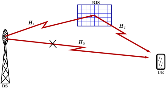
The first RIS-mmWave model assumes that a BS, which is aided by one RIS, serves one UE, as shown in Fig. 2. Assume that BS employs transmit antennas and supports at most data streams, RIS employs reconfigurable reflecting elements, and UE has receive antennas and data streams. Assume that both direct propagation link (DPL) and reflection propagation link (RPL) between BS and UE may exist. As shown in Fig. 2, the channel transfer matrices are from BS to UE, from BS to RIS, and from RIS to UE.
In mmWave communications, the Saleh-Valenzuela model [19, 20] is often invoked to represent the mmWave MIMO channels. For example, assume that uniform linear array (ULA) are employed at BS and UE, while uniform planar array (UPA) with is implemented at RIS. Then, when the far-field case and narrow-band slow fading are assumed, the channel matrices can be represented in the forms of
| (22a) | ||||
| (22b) | ||||
| (22c) | ||||
In the above channel models, corresponds to LoS path, while the other , and are non-line-of-sight (NLoS) paths, respectively, in , and . For the th component path, the terms in (22) have the meanings as follows. are the gains. and represent the angle-of-departure (AoD) and angle-of-arrival (AoA), respectively, of ULA. and represent the azimuth and elevation AOAs at RIS, while and represent the azimuth and elevation AODs at RIS. More specifically, and can be represented in the form of [15, 20]
| (23) |
where (or ), the normalized is obtained from the physical angle (or ) as
| (24) |
where is wavelength and is antenna spacing. The response vector of RIS can be expressed as [21, 20]
| (25) |
where denotes the Kronecker product, and , with and denoting the antenna spacing in and directions, respectively, and
| (26) |
Note that should also take into account the reflection loss of RIS, which may be the same or different for different reflectors.
As shown in Fig. 2, the reflection matrix of RIS is expressed as , which is typically diagonal in passive reflection, but may be non-diagonal when advanced design is available in the future [10]. In general, the elements of can be expressed as , where represents the reflection gain (magnitude) of the signal impinging on the th element and reflected by the th element, while is the phase-shift added in the impinging-reflection process. According to definition, a passive RIS element can only modify the phase of an incident signal, while an active RIS element may adjust both the gain and phase of an incident signal. Hence, for passive RIS, any element’s reflection gain satisfies , which is taken account by . By contrast, for active RIS, it is possible that some elements have the gains of , which are provided by amplification circuitries [9].
Let , , and , be a data vector sent from BS to UE. Then, based on the above definitions, the received signals at UE can be represented as
| (27) | ||||
| (28) |
where is the equivalent composite channel matrix between BS and UE, is the complex Gaussian noise, each element of which is distributed with zero mean and a variance , and implements transmit beamforming, which may be a digital beamformer or a hybrid beamformer [15, 22]. In some cases, may be represented as to clearly show that there is a beam sent towards DPL and a beam sent towards RPL, with the power assigned between two beams controlled by the parameter . Correspondingly, can be viewed as a full blockage of DPL. Note that, even when the LoS path between BS and UE is blocked, as shown in (22), may contain NLoS paths. In this case, both DPL and RPL may be at a similar power-level, making power-allocation efficient in RIS-mmWave systems. Otherwise, when a LoS path exists in DPL, it should dominate the received signal of UE, making the employment of RIS less effective or not necessary. Accordingly, all BS transmit power should be assigned to DPL.
After UE uses a combiner , which may also be a digital or hybrid combiner [15, 23], to process the received signals, it obtains
| (29) |
where .
When both BS and UE have CSI, meaning that they know , and transceivers are optimally designed for a given , the achievable sum-rate (capacity) can be derived from (28) by following the principles of MIMO [24, 25, 26], and formulated as
| (30) |
where is the covariance matrix of and is the covariance matrix of transmit signals. Note that, to achieve the capacity of (III), it is the overall , instead of , that is required to be optimally designed according to .
Based on Equation (III), let us carry out some analysis and gain some observations in the following two cases:
-
C1:
When RIS is treated as a component of channel, the RIS-mmWave system’s capacity is achieved via the joint design of transmitter and receiver.
-
C2:
When RIS is considered as a part of the transceiver, such as, when RIS is fully controlled by BS via a dedicated channel, the RIS-mmWave system’s capacity is achieved via the joint design of transmitter, RIS and receiver.
Specifically, in the case of C1, we may have the following observations:
-
•
Given a RIS phase-shift matrix , the system is only required to estimate and the composite channel to achieve optimum design.
-
•
Given the estimated and composite channel , the optimum design includes and the corresponding combiner .
-
•
The optimum design of is dependent on the statistics of , and .
-
•
When is fixed, is then fixed, and the RIS-mmWave system is reduced to a conventional MIMO system, whose optimal transceiver design is well-known [25, 26]. More specifically, the capacity can be achieved via the singular-value decomposition (SVD) of supported by the water-filling assisted power-allocation derived based on the singular values of . Furthermore, there are numerous transceiver optimization algorithms, which provide the design alternatives that can attain various trade-off between performance (efficiency) and complexity.
-
•
The capacity of MIMO system is dependent on the number of non-zero singular values, as well as the values and distributions of the non-zero singular values. Hence, in RIS-mmWave systems, should be optimized to satisfy the requirements for achieving the capacity after the water-filling power-allocation.
In comparison with the case of C1, the optimization and design of the RIS-mmWave system in the case of C2 are more demanding. Below are some observations:
-
•
System is required to estimate the individual channels of , and , which is highly challenging and resource-greedy, and generates large delay for a RIS-mmWave system employing a large RIS.
-
•
Given the estimated channels, optimum transceiver design includes , and the corresponding combiner . The optimization of and is coupled. Hence, they need to be jointly optimized to achieve capacity.
-
•
The optimization of is dependent on , and .
-
•
Given , and , may be optimized to make the resulted satisfy the required properties, as above-mentioned, for maximizing the sum-rate of system.
Explicitly, the design for achieving the capacity of RIS-mmWave systems in either of the above-mentioned cases is high complexity. Hence, the design of relatively low-complexity algorithms for operation in RIS-mmWave systems has drawn the main attention in research, as seen in [27, 8] and the references there in333The models considered in literature are usually the simplified versions of the RIS-mmWave model shown in Fig. 2, by assuming, such as, single transmit antenna, single receive antenna, DPL and RPL contain only one LoS path, blocked DPL, etc.. Typically, in a RIS-mmWave model as considered, the phase-shifts of RIS, transmit beamformer and receive combiner can be optimized iteratively to reduce complexity. Furthermore, instead of working directly on the capacity of a RIS-mmWave system444To the best of our knowledge, the capacity of the RIS-mmWave MIMO systems, as that shown in Fig. 2, is still unknown at the time of writing the book., its sum-rate is typically considered. For this purpose, (29) is divided into observations corresponding to the transmitted symbols as
| (31) |
where is the -th column of , . Furthermore, for the sake of generality, a noise term is added to account for the noise possibly introduced by RIS, which is assumed to obey the distribution . Let . Then, (31) can also be written as
| (32) |
where, at the righthand side, the first term is the desired signal, the second term is interference, and the other terms are Gaussian noise. From (32), the SINR can be represented as
| (33) |
Accordingly, the sun-rate is given by
| (34) |
which is conditioned on , and , as well as and designed based on the channels. The sun-rate of (34) can be directly employed as the objective function for optimization. Furthermore, when the total power consumed for achieving this sum-rate is formulated, the optimization objective function can also be defined in terms of the energy-efficiency, which is given by the ratio of [28].
According to the above analysis, the general optimization problem to maximize the sum-rate of (34) includes finding the solutions for , and , under certain constraints. However, jointly optimizing these variables for the optimum solutions is practically impossible. Hence, the practically meaningful algorithms are desired, which usually optimize these variables in iterative way to obtain the solutions of approximately optimum. Below a few of simplified models are considered.
The simplest model assumes a BS with one transmit antenna, a UE with one receive antenna, fully blocked DPL, one passive RIS with reflection elements, only LoS path between BS and RIS and LoS path between RIS and UE. In this simplified model, . Accordingly, the received signal at UE can be written as
| (35) |
where is defined by (25) or (III), and are gains of the BS-RIS and RIS-UE links555Note that, more explicitly, should be replaced by , where is the common reflection coefficient of RIS elements, which is uncontrollable by the optimization process.. Express the th element of as , and of as . Then, (III) can be written as
| (36) |
Hence, to make the signals be coherently added together at UE, the phases of RIS must be set as
| (37) |
yielding the receive SNR
| (38) |
Equation (38) infers that the attainable SNR at UE scales with the square of the number of RIS elements, i.e., . However, according to [29], this is only valid in far-field scenario, when RIS is physically small relative to the distances between BS and RIS and between RIS and UE. Otherwise, when operated in the near-field scenario, where RIS’ physical size is comparable to the BS-RIS and RIS-UE distances, the SNR only scales with of the number of RIS elements.
In addition to the assumptions made in the above simplest model, now we assume that there also exists a path between BS and UE, i.e. DPL, which is not necessary the LoS path. Then, corresponding to (36), the model can be described as
| (39) |
Explicitly, the phases of RIS elements need to be set as
| (40) |
yielding the receive SNR
| (41) |
Next, let us consider the model where BS has transmit antennas, passive RIS has elements, UE has one receive antenna, only RPL exists and there is only one path from BS to RIS and one path from RIS to UE. Accordingly, the observation obtained at UE can be written as
| (42) | ||||
| (43) |
where and are channel gains, with also accounting for the reflection loss, and is the beamforming vector used by BS for transmission to RIS.
According to (42), when is given, can be optimized as
| (44) |
to maximize the receive SNR at UE. Alternatively, using the definitions below (III), and also defining and the th element of as , (43) can be represented as
| (45) |
Explicitly, the design of
| (46) |
maximizes receive SNR, yielding
| (47) |
and SNR of , showing that the achievable SNR also linearly scales with the number of elements of BS antenna array.
Following the above model where BS is equipped with an array but no DPL, now we assume that there is a path directly from BS to UE. Furthermore, to explicitly demonstrate the effect of power-allocation between DPL and RPL, we set , where forms a beam towards DPL and forms a beam towards RPL. Furthermore, for simplicity, we assume that these two beams are orthogonal. Under these assumptions, the observation at UE can be represented as
| (48) |
From (48) we can be inferred that the optimum design to maximize SNR requires to jointly design , , and . Below we consider a sub-optimum method, which designs the precoders and RIS’ phase shifts as
| (49a) | ||||
| (49b) | ||||
| (49c) | ||||
where is due to the representation of . Substituting these terms into (48) yields
| (50) |
Accordingly, the receive SNR is
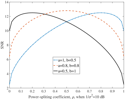
| (51) |
which is a function of the power-allocation coefficient between DPL and RPL. As shown in Fig. 3, is a concave function of , which has one maximum at
| (52) |
with the definitions of and . Applying this into (51) gives the maximum SNR of
| (53) |
Equation (52) infers, also as seen in Fig. 3, that if , meaning that DPL is dominant, most BS transmit power should be assigned to DPL to enable the maximum SNR. By contract, if , i.e., RPL is dominant, most BS power should be allocated to RPL to maximize SNR. If , assigning half of BS power to both DPL and RPL maximizes the receive SNR. In fact, the power-allocation of (52) implements the maximal ratio combining (MRC) [3] of the signals received by UE from DPL and RPL.
Furthermore, (51) and (52) infer that the antenna array employed by BS does not affect the power-allocation between DPL and RPL. The power-allocation is only relied on the gains of DPL and RPL.
In contrast to the above models of all assuming passive RIS, finally, following [9], we consider an active RIS that introduces reflective noise. The system is also under the constraints of both the total transmit power at BS and the total transmit power at RIS. Assume that BS is capable of attaining all the channel knowledge of , and , and UE knows . In this case, UE can simply design a to maximize the rate between RIS and UE based on by assuming the virtual observations of , where is a designed virtual beamformer for RIS to send information to UE. As BS knows , and , it can also design the same as UE. Hence, it can optimize its precoder in zero-forcing (ZF) principle [24] to fully remove the interference between the received symbols at UE. Consequently, (33) can be written as
| (54) |
From (29) and (31), the transmit power of BS and RIS can be derived, which can be expressed as
| (55a) | ||||
| (55b) | ||||
respectively. Hence, the optimization problem for designing and to maximize sum-rate can be described as
| (56a) | ||||
| s.t. | (56b) | |||
| (56c) | ||||
| (56d) | ||||
where the constraint C1 forces the system to be free of ISI.
It can be readily realized that jointly solving the above optimization problem is extremely hard. Instead, iterative optimization of and can be executed, such as, by the methods modified from those introduced in [9]. Note that, in the above optimization problem, we assume that has been separately designed based only on to maximize the sum-rate between RIS and UE.
Solving the above optimization problem has the implication of resource-allocation. Specifically, the design needs to find the solutions for the power assigned between DPL and RPL. Simultaneously, for both DPL and RPL, the design needs to find the solutions to assign corresponding power to the different beams between BS and RIS, between RIS and UE, and between BS and UE.
IV RIS-mmWave: Single-RIS Multiple Users
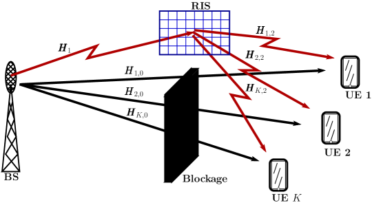
Above a RIS-mmWave model with single UE is considered. Now we extend it to the scenario of multiple UEs, with the system diagram as shown in Fig. 4. We use the same settings and assumptions as those in Section III, in addition to replacing by , by , by , by , by , and by . Note that, and are the same as them in Section III, which are common to all UEs. Then, by following Section III, it can be shown that the observations obtained by the th UE can be represented as
| (57) | ||||
| (58) |
where is the equivalent composite channel between BS and UE , and is the RIS processing generated noise forwarded to UE .
UE uses the combiner to form the decision variables for detecting its symbols, yielding
| (59) |
where in the second equation, , the first term corresponds to the desired UE , and the second term is multi-user interference (MUI) on UE . Depended on the BS precoder and the combiner of UE , the symbols in may or may not interfere with each other.
Corresponding to (32), the decision variable for detecting the th symbol of UE can be expressed as
| (60) |
where is applied. From (IV) the SINR for detecting a symbol of UE can be derived to be
| (61) |
Accordingly, the sun-rate is given by
| (62) |
where by definition, and .
Then, to maximize the sum-rate of the RIS-mmWave system under the transmit power constraint at both BS and RIS, and the constraint of zero ISI and MUI, the optimization problem can be described as
| (64a) | ||||
| s.t. | (64b) | |||
| (64c) | ||||
| (64d) | ||||
| (64e) | ||||
Note that in the above problem, if each data symbol is constrained to use at most one unit of energy for its transmission, we have .
As jointly solving the above optimization problem is extremely difficult, iterative optimization is usually implemented. Furthermore, considering that, in practice, the number of array elements of a UE is usually significantly smaller than that of BS and that of RIS, little performance gain can be attained via the iteration with respect . Instead, can simply be designed to maximize the sum-rate between RIS and individual UEs, without considering the inter-effect between UEs and the channels between BS and RIS. After are obtained and fixed, the ISI and MUI can be tackled by the designs of and . Following the principle of massive MIMO [30], when the number of array elements at BS and the number of RIS elements are sufficiently large, ZF-assisted precoding is near-optimum. Furthermore, ZF-assisted precoding often provides the results that are relatively easy to analyze. Hence, the constraints of zero ISI and zero MUI are imposed, as stated in (64)(b) and (64)(c), on the optimization. Note that, when and are given, the ZF precoding becomes a typical ZF transmitter preprocessing problem in MIMO, the solution of which (including power-allocation) can be found, for example, in [24].
With the above constraints, for example, an iterative optimization for and may be generally described as Algorithm 1. Note that the constraints of (64)(b) and (64)(c) may not be imposed to release the ZF precoding constraint. Furthermore, we can be inferred that the optimization in Algorithm 1 may involve the power-allocation between DPLs and RPLs, and between BS transmission and RIS transmission, as well as the power-allocation among the data streams of all UEs.
Below we consider a few of simplified models as well as their optimization.
The first one assumes no DPL, and that BS employs transmit antennas to support UEs of each employing single antenna with the aid of a passive RIS of elements. Hence, , , and no noise added at RIS. Accordingly, the observation obtained by UE can be written as
| (65) |
where is the channel vector from RIS to UE , , and with for implementing precoding and for scaling the precoder to make the transmit signal satisfy the power constraint.
The precoder matrix and phase shift matrix in this model can be optimized using different methods. For example, by assuming the ZF precoding, the optimization can be changed to optimizing the power-allocation and phase shifts. In detail, let , and , which is a matrix. Then, we have
| (66) |
Given , and , and assuming that and , the ZF solution for precoding is given by [24]
| (67) |
Correspondingly, the total transmit power is
| (68) |
where returns the trace of square matrix .
Substituting (67) into (66) yields
| (69) |
Hence, the SNR of UE is , which is a function of . Accordingly, the sum-rate is
| (70) |
Consequently, constrained on the ZF precoding, the optimization becomes to iteratively solve the problem for the power-allocation and the phase shifts in . Specifically, during an iteration, when is given, the power-allocation for can be described as
| (71a) | ||||
| (71b) | ||||
It can be shown that the above problem has the close-form solutions of the water-filling style.
Note that a simpler solution [24] to can be readily obtained from the constraint (71) (b) by letting , yielding
| (72) |
Furthermore, an optimization problem that has the meaning of maximal SNR can be stated as [24]
| (73a) | ||||
| (73b) | ||||
which also has the closed-form solution, as detailed in[24].
On the other side, when is fixed, can be obtained from solving the unconstrained problem described as [31]
| (74a) | ||||
| (74b) | ||||
Its solution to can be derived with the aid of, such as, the gradient descent approach or the sequential fractional programming method [31].
Another method introduced in [32] is using the deep reinforcement learning (DRL) algorithm to directly solve the sum-rate maximization problem described as
| (75a) | ||||
| (75b) | ||||
| (75c) | ||||
which motivates to jointly find the solutions to and , where the SINR in terms of UE is
| (76) |
The second simplified model extends the above one by invoking a DPL from BS to each of UEs. Let the channel from BS to UE be expressed as a -length vector . Then, corresponding to Eqs. (IV) and (66), we have
| (77) |
and
| (78) |
where .
From (77), the SINR can be derived to be
| (79) |
Based on (78), it can be shown that, when is fixed, the ZF solution to is
| (80) |
associated with the power constraint of
| (81) |
Then, and can be iteratively optimized using the similar approaches introduced with the first simplified model, as shown in (71)-(74), upon invoking the and provided by (80) and (81).
Built on (77)-(79), [33] considered a weighted sum-rate maximization problem, described as
| (82a) | ||||
| (82b) | ||||
| (82c) | ||||
where are weights. This problem can also be sloved using the iterative method. Specifically, when given , can be optimized using, such as, the weighted MMSE algorithm [34]. Then, for a given , the phase shift matrix can be optimized by the Riemannian conjugate gradient method [33] to maximize the weighted sum-rate. Additionally, in [33], the non-convex block coordinate descent (BCD) method [35] was introduced to solve the optimization problem described by (82), in the cases when CSI is ideal or non-ideal.
Instead of using the sum-rate as the optimization objective, as above shown, a more practical optimization problem can be designed to minimize the total transmit power, which is described as [36]
| (83a) | ||||
| (83b) | ||||
| (83c) | ||||
where is the minimum SINR requirement of UE . The solution to this problem can be derived via the iterative optimization of two sub-problems [36]. One optimizes for a fixed using, such as, the second-order cone program (SOCP), convex semidefinite program (SDP), etc. After some transform and approximation, the second one optimizes for the fixed , which can be solved using the existing convex optimization methods, such as, CVX [37].
Let us continue on the second simplified model by assuming that , , and both and are very large, i.e., in the concept of massive MIMO. Then, from the principles of massive MIMO, the rows of in (78) are nearly orthogonal to each other, regardless of the phase shifts applied in . This in turn means that UEs can be spatially separated without interference between each other. Hence, the matched-filtering (MF) precoder is nearly optimum. Consequently, the precoder and can be firstly optimized with respect to individual UEs. Then, a phase-shift matrix is obtained by combining the individual phase-shift matrices obtained from the individual optimizations. Below an exemplified method towards the objective is analyzed.
Since it is in the principle of massive MIMO, we can assume that the DPL and RPL of a UE are orthogonal. Hence, the precoders for DPL and RPL can be optimized separately without any loss of performance, provided that the signals conveyed by DPL and RPL are coherently added at a UE. Considering this property and expressing , where for , the observation at UE can be represented as
| (84) |
where, again, implements the power-allocation between the DPL and RPL of UE . When and are known, can be found from (52).
From (IV), the optimum precoder for DPL is
| (85) |
Given and , the optimum precoder for RPL is
| (86) |
which is a function of and that need to be determined.
Alternatively, when is given, then, let express , where denotes the th row of , the reflected term in (IV) can be expressed as
| (87) |
Explicitly, to add coherently the signals arriving at UE , the phase shifts of RIS have the determinate solutions of
| (88) |
for , where returns the phase of the complex number . Consequently, (IV) can be expressed as
| (89) |
What left here is to derive a from the optimization problem
| (90a) | ||||
| (90b) | ||||
Inferred by the principles of massive MIMO, the solution to should be in the form of
| (91) |
where is for normalizing to unit length, are the weights needing optimization under the constraint of . Substituting (91) into (90) and making use of the property of , when is large, we obtain the objective function
| (92) |
where , which are given values. Therefore, can be obtained from the solutions of the optimization problem described as
| (93a) | ||||
| (93b) | ||||
| (93c) | ||||
This is a simple linear programming problem [38, 39, 40]. The solution is assigned to the , yielding
| (94) |
When the RIS-mmWave system supports UE, the design of precoder and phase-shifts finishes at this point. However, the current RIS-mmWave system supports UEs. For each of UEs, a separate is generated, and the ’s of different UEs are different. Hence, after obtaining corresponding to the individual UEs, a joint needs to be designed, which can be conceptually formulated as
| (95a) | ||||
| (95b) | ||||
where means to find a function for the purpose. Below are some possible approaches for the objective. First, with the aid of the properties of massive MIMO, which implies that the channels of individual UEs are similar and nearly orthogonal, a reflection matrix can be obtained as
| (96) |
where is a diagonal matrix containing the real values to achieve the power constraint on RIS elements or the constraint of . Specifically, if RIS is able to implement digital reflection, i.e., it can amplify the signals incident on the surface, we can let , where the constant is chosen as
| (97) |
In this case, the reflection matrices are added linearly, enabling that a UE’s signals sent by BS and impinging on RIS surface as well as the signals conveyed on DPL and RPL are coherently added at the UE. Consequently, if the massive RIS-mmWave system makes all UEs’ channels orthogonal with each other, the design of precoders and reflection matrices completes. Otherwise, a further updating of precoders in the principles of, such as ZF, may be implemented to remove the inter-interference between UEs.
By contrast, if the RIS reflectors are fully passive reflectors requiring , the value of is then given by
| (98) |
In this case, the reflection matrices are added non-linearly, i.e., different diagonal elements in a reflection matrix may be weighted by different values given by (98). Consequently, the joint reflection matrix (96) is highly likely not the linear combination of the individual reflection matrices for UEs. This results in that a UE’s signals sent by BS and impinging on RIS surface as well as that sent on DPL are not coherently added at the UE. To solve this problem, the BS precoders for individual UEs can be updated using the joint phase-shift matrix (96) as
| (99) |
Again, if there is still interference between UEs after the above optimizations with respect to the individual UEs, a further ZF precoding stage may be implemented at BS to remove the interference between UEs.
The second method to find a joint is formulated as
| (100) |
where is a diagonal matrix obtained from with only non-zero elements of one, which assign RIS reflection elements to UE . Explicitly, fixed assignments or the dynamic assignments satisfying a defined objective may be implemented. This approach guarantees that out of elements are optimum towards a UE, while the other elements’ phases are randomly set for this UE. Hence, another stage of precoder optimization, as shown in (99), or even a further stage of ZF precoder design are needed.
In summary, the above processes can be summarized as Algorithm 2.
- 1.
- 2.
-
3.
Update using (99) , if full passive RIS; or
-
4.
based on , BS jointly designs for all UEs in the principles of ZF, or other, precoding.
The joint RIS phase-shift matrices (96) and (100) imply that the performance in terms of one UE degrades, as the number of UEs increases. This is the result of two factors. First, when there are UEs, RIS has to divide its power to reflect signals towards directions, as shown in (97) and (98). Hence, when increases, less power is delivered by RIS to a specific UE. Second, for passive RIS, as increases, the phase-shift matrix becomes more random, as explained in (96) and (100). Hence, the signals from BS are more randomly reflected to UEs, which also results in performance degradation. Furthermore, we might be inferred that in passive RIS-mmWave systems, a random reflection matrix may be expected to be near-optimum, if . This however needs further research to verify.
V RIS-mmWave: Multiple-RISs Multiple Users
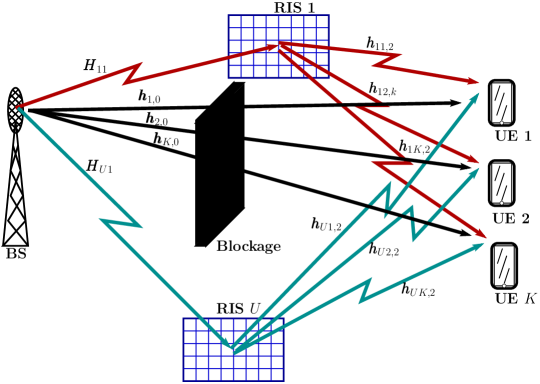
This section further extends the RIS-mmWave model considered in Section IV to a model with RISs [41, 42], as shown in Fig. 5. To be more specific, the model assumes one BS with an array of antennas, RISs with the th RIS having reflection elements, and UEs of each equipped with single antenna for simplicity. However, the single-antenna UEs can be straightforwardly extended to the general UEs of each with multiple antennas. Again, downlink transmission is considered. Under these settings and assumptions, the baseband transmit signal of BS can be expressed as
| (101) |
where the precoding vector , precoding matrix and data vector are the same as them in Section IV.
Assume that a DPL may exist between BS and a UE, in addition to the RPLs. Accordingly, the received observation of UE can be expressed as
| (102) |
where is an association parameter, with denoting that the signal to UE is via RIS , and otherwise, while the other arguments in (102) have the same definitions as those in (77), except replacing by . Similarly, corresponding to (78), the observations of UEs can be expressed as
| (103) |
where and .
From (102), the SINR of UE is
| (104) |
According to (102) and (103), when given the channels , and , the optimization of the considered RIS-mmWave system includes:
-
•
Associations of UEs with RISs;
-
•
Optimization of ;
-
•
Optimization of precoder .
Due to the high complexity and non-convexity of the joint optimization problem, the above-mentioned optimization may only be executed separately and in the iteration ways. For example, UE associations can be firstly carried out based on the strength of the pilot signals sent by BS, reflected by RISs and received by UEs. After associations, BS can choose to send information to UEs via their associated RISs with the aid of beamforming. Accordingly, RISs’ reflection matrices and BS’ precoder can be optimized using the iterative methods similar to that considered in Section IV.
Instead of UE association, in [42], switching ‘on-off’ of RISs is considered to improve energy-efficiency. Accordingly, (102) is represented as
| (105) |
where turns ‘on’ a RIS, while switches off a RIS. Correspondingly, the SINR of UE is
| (106) |
The system’s sum rate is expressed as
| (107) |
where is bandwidth.
For power consumption, the BS transmit power, BS circuit power, RIS circuit power, and RIS transmit power are included, having the representation of [42]
| (108) |
where, on the righthand side, the first term denotes the power consumed by BS for signal transmission, is the power amplification efficiency of BS, the second term is the circuit (or signal processing) power of BS, the third term is the power consumption of RISs, with representing the power consumption per RIS element, and the last term is the total power consumed by UEs to receive their information.
Then, in [42], the BS precoder, reflection matrices and the ‘on-off’ states of RISs are optimized to maximize the energy-efficiency under the minimum rate, , requirement for each of UEs and the constraint of the total BS transmit power of . The optimization problem is formulated as
| (109a) | |||
| (109b) | |||
| (109c) | |||
| (109d) | |||
| (109e) | |||
The optimization problem stated in (109) is a mixed-integer nonlinear problem, which is extremely hard to solve. In [42], considering the single- and multi-user cases, two iterative algorithms were developed for solving the problem to obtain the sub-optimum solutions.
Below we consider the massive RIS-mmWave scenario where and of the th RIS is significantly larger than the number of UEs associated with it. Hence, following the principles of massive MIMO, the channels from BS to different UEs and that from BS to the same UE via different links can be assumed to be orthogonal with each other. We assume that the associations of UEs are carried out before the optimization of BS precoder and RISs’ reflection matrices. In practice, this can be achieved during the beam search stage, with the aid of the pilot beams sent by BS via all possible links and also all possible beams [43]. Based on the measurements of pilot beams, which may include signal strength, delay, AOA, AOD, and even the positions of UE and RISs, a UE decides which RISs it associates.
Specifically, if each UE is regulated to be associated with only one RIS, after the association, the optimization of and is the same as that considered in the massive RIS-mmWave case in Section IV.
By contrast, when each UE is allowed to be associated with multiple RISs, the optimizations of and can be based on the observation
| (110) |
where is the number of RISs that UE associates with. Eq. V is the simplified equation of (107) by applying the assumptions that the channels from BS to different UEs are orthogonal, and that the channels from BS to a UE via different links are also orthogonal. Hence, we have
| (111) |
where and are orthogonal with each other and are unity length, are power-allocation coefficients.
From (V), we can readily know that
| (112a) | ||||
| (112b) | ||||
Substituting (112) into (V) gives
| (113) |
where can be designed to maximize [42]. Then, a that is common to all UEs associated with the th RIS is calculated and may be further updated by following the discussion in Section IV.
From (113), the SNR of UE is
| (114) |
which can be maximized via power-allocation. Let and . Then, (114) is represented as
| (115) |
As are positive numbers, the optimization problem for obtaining can be stated as
| (116a) | ||||
| (116b) | ||||
which can be readily solved using the method of Lagrange multipliers, yielding
| (117) |
Substituting them to (115) obtains
| (118) |
showing that the power-allocation by BS to the beams towards one UE implements the MRC result at the UE. Following the principle of MRC, higher power is assigned to a stronger beam. If a beam is weak, BS assigns it little power. In practice, the weak beams may be simply switched off to save power of both BS and RISs, also because the channel estimation of weak beams is difficult and unreliable.
VI Concluding Remarks
This chapter addressed the principles of RIS-mmWave and the optimization in RIS-mmWave systems. First, a conceptual example was provided to explain the various wireless communication implementation strategies, when receiver, transmitter or/and channel reflector(s) have CSI. Then, the optimization in the context of three RIS-mmWave models were respectively analyzed. All the three models assume one BS, while the first one assumes one RIS and one UE, the second one assumes one RIS and multiple UEs, and the third one assumes multiple RISs and multiple UEs. Furthermore, some sub-models under the above three were also considered. The analyses show that in the simplest model with one UE, the optimization objective is to design BS precoder and RIS phase-shifts, so that the signals arriving at UE are coherently added. By contrast, when there are multiple UEs, the optimization needs to mitigate inter-UE interference, in addition to maximizing individual UE’s performance. Furthermore, when there are multiple RISs, a stage of optimization for UEs’ association with RISs is required. Additionally, it is shown that when RIS-mmWave systems satisfy the massive MIMO conditions, the BS precoder and RIS phase-shifts of individual UEs can be independently designed, making the optimization relatively simple.
While the deployment of RISs can help solve the blockage problem in mmWave communications, there are also challenges in the design and optimization for high-efficiency. The first and also most critical challenge is channel acquisition. As shown in Sections III-V, in a RIS-mmWave system implementing CSI-relied RIS optimization, there are three channels, namely , and , to estimate. While of DPL can be estimated by the conventional methods, the acquisitions of and of RPL are not straightforward. This becomes especially difficult, when a RIS is equipped with a large number of reflection elements, which, however, may be the case in practice. Here, the main challenge is that RIS is typically assumed to be simple, passive operation, and of extremely low-power consumption. Furthermore, the size of individual reflection elements is supposed to be small, which leads to the channel acquisition with weak signals. Because of the above-mentioned constraints plus channel acquisition under weak signals, it is expected that RIS can hardly achieve satisfactory channel acquisition by itself.
Another challenge is the RIS phase-shift optimization, especially, when the number reflection elements is large. From the analyses in Sections III-V we can realize that whenever the CSI-relied phase-shift optimization is implemented, the optimization of RIS-mmWave systems becomes more involved and challenging, regardless of the active RIS or passive RIS employed. Furthermore, it seems that when the number of UEs increases, the benefit added by the CSI-relied RIS optimization reduces, which is especially true, when passive RIS is assumed due to the unit amplitude constraint on per reflection element. For example, assume a three UE system where a RIS phase-shift is required to set for UE 1, for UE 2, and for UE 3. As the phase-shift can only be set to one value, by adding these values and normalizing the result to unit amplitude, the actual phase shift configured is about and the amplitude normalization factor is about . When another reflection element has three corresponding values of , and , its phase shift is and the amplitude normalization factor is . This simple example explains that in passive RIS, the optimum phase-shift matrices designed from the optimization with respect to individual UEs may not be beneficial in general, when the number of UEs is big. However, the situation in massive RIS-mmWave expects further research.
The solutions around the above dilemma might be as follows. First, the RIS phase-shift matrix may simply be randomly set. In this case, only the composite channel needs to be estimated, which significantly lessens the challenges from channel estimation and system optimization. The second approach is discretizing into a set , which may be designed according to the specific application scenarios. In this case, BS only needs to estimate the composite channels associate with these candidate phase-shift matrices during optimization. Finally, in the massive RIS-mmWave scenarios, the method suggested by (100) might be practical, but further research for confirmation is expected.
References
- [1] R. Steele and L. Hanzo, Eds., Mobile Radio Communications, 2nd ed. IEEE Press-John Wiley, 1999.
- [2] J. D. Parsons, The Mobile Radio Propagation Channel, 2nd ed. John Wiley & Sons LtD., 2001.
- [3] J. G. Proakis, Digital Communications, 5th ed. McGraw Hill, 2007.
- [4] L.-L. Yang, “Time-hopping multicarrier code-division multiple-access,” IEEE Transactions on Vehicular Technology, vol. 56, no. 2, pp. 731 – 741, March 2007.
- [5] R. Hadani, S. Rakib, M. Tsatsanis, A. Monk, A. J. Goldsmith, A. F. Molisch, and R. Calderbank, “Orthogonal time frequency space modulation,” in 2017 IEEE Wireless Communications and Networking Conference (WCNC), 2017, pp. 1–6.
- [6] M. Di Renzo, A. Zappone, M. Debbah, M.-S. Alouini, C. Yuen, J. de Rosny, and S. Tretyakov, “Smart radio environments empowered by reconfigurable intelligent surfaces: How it works, state of research, and the road ahead,” IEEE Journal on Selected Areas in Communications, vol. 38, no. 11, pp. 2450–2525, 2020.
- [7] M. A. ElMossallamy, H. Zhang, L. Song, K. G. Seddik, Z. Han, and G. Y. Li, “Reconfigurable intelligent surfaces for wireless communications: Principles, challenges, and opportunities,” IEEE Transactions on Cognitive Communications and Networking, vol. 6, no. 3, pp. 990–1002, 2020.
- [8] Y. Liu, X. Liu, X. Mu, T. Hou, J. Xu, M. Di Renzo, and N. Al-Dhahir, “Reconfigurable intelligent surfaces: Principles and opportunities,” IEEE Communications Surveys & Tutorials, vol. 23, no. 3, pp. 1546–1577, 2021.
- [9] Z. Zhang, L. Dai, X. Chen, C. Liu, F. Yang, R. Schober, and H. V. Poor, “Active RIS vs. passive RIS: Which will prevail in 6G?” IEEE Transactions on Communications, vol. 71, no. 3, pp. 1707–1725, 2023.
- [10] Q. Li, M. El-Hajjar, I. Hemadeh, A. Shojaeifard, A. A. M. Mourad, B. Clerckx, and L. Hanzo, “Reconfigurable intelligent surfaces relying on non-diagonal phase shift matrices,” IEEE Transactions on Vehicular Technology, vol. 71, no. 6, pp. 6367–6383, 2022.
- [11] H. L. Bertoni, Radio Propagation for Modern Wireless Systems. Prentice Hall PTR, 2000.
- [12] T. S. Rappaport, Wireless Communications Principles and Practice, 2nd ed. New York: Prentice Hall, Inc, 2002.
- [13] W. Tang, M. Z. Chen, X. Chen, J. Y. Dai, Y. Han, M. Di Renzo, Y. Zeng, S. Jin, Q. Cheng, and T. J. Cui, “Wireless communications with reconfigurable intelligent surface: Path loss modeling and experimental measurement,” IEEE Transactions on Wireless Communications, vol. 20, no. 1, pp. 421–439, 2021.
- [14] X. Wang, L. Kong, F. Kong et al., “Millimeter Wave Communication: A Comprehensive Survey,” vol. 20, no. 3, pp. 1616–1653, 2018.
- [15] R. W. Heath, N. Gonzalez-Prelcic, S. Rangan, W. Roh, and A. M. Sayeed, “An overview of signal processing techniques for millimeter wave MIMO systems,” IEEE Journal of Selected Topics in Signal Processing, vol. 10, no. 3, pp. 436–453, 2016.
- [16] M. Hasna and M.-S. Alouini, “End-to-end performance of transmission systems with relays over rayleigh-fading channels,” IEEE Transactions on Wireless Communications, vol. 2, no. 6, pp. 1126–1131, 2003.
- [17] A. F. Molisch, Relaying, MultiHop, and Cooperative Communications, 2011, pp. 521–563.
- [18] M. Munochiveyi, A. C. Pogaku, D.-T. Do, A.-T. Le, M. Voznak, and N. D. Nguyen, “Reconfigurable intelligent surface aided multi-user communications: State-of-the-art techniques and open issues,” IEEE Access, vol. 9, pp. 118 584–118 605, 2021.
- [19] A. Saleh and R. Valenzuela, “A statistical model for indoor multipath propagation,” IEEE Journal on Selected Areas in Communications, vol. 5, no. 2, pp. 128–137, 1987.
- [20] H. Liu, S. Lu, M. El-Hajjar, and L.-L. Yang, “Machine learning assisted adaptive index modulation for mmwave communications,” IEEE Open Journal of the Communications Society, vol. 1, pp. 1425–1441, 2020.
- [21] Z. Gao, Z. Wan, D. Zheng, S. Tan, C. Masouros, D. W. K. Ng, and S. Chen, “Integrated sensing and communication with mmWave massive MIMO: A compressed sampling perspective,” IEEE Transactions on Wireless Communications, vol. 22, no. 3, pp. 1745–1762, 2023.
- [22] X. Huang, Y. J. Guo, and J. D. Bunton, “A hybrid adaptive antenna array,” IEEE Trans. on Wireless Communications, vol. 9, no. 5, pp. 1770–1779, May 2010.
- [23] C. Pradhan, A. Li, L. Song, B. Vucetic, and Y. Li, “Hybrid precoding design for reconfigurable intelligent surface aided mmwave communication systems,” IEEE Wireless Communications Letters, vol. 9, no. 7, pp. 1041–1045, 2020.
- [24] L.-L. Yang, Multicarrier Communications. Chichester, United Kingdom: John Wiley, 2009.
- [25] E. Telatar, “Capacity of multiantenna Gaussian channels,” AT& T Bell Laboratories, Tech. Memo., June 1995.
- [26] I. E. Telatar, “Capacity of multiantenna Gaussian channels,” European Transactions on Telecommunications, vol. 10, no. 6, pp. 585–595, Nov./Dec. 1999.
- [27] B. Feng, J. Gao, Y. Wu, W. Zhang, X.-G. Xia, and C. Xiao, “Optimization techniques in reconfigurable intelligent surface aided networks,” IEEE Wireless Communications, vol. 28, no. 6, pp. 87–93, 2021.
- [28] J. Singh, S. Srivastava, S. P. Yadav, A. K. Jagannatham, and L. Hanzo, “Energy efficiency optimization in reconfigurable intelligent surface aided hybrid multiuser mmwave MIMO systems,” IEEE Open Journal of Vehicular Technology, vol. 4, pp. 581–589, 2023.
- [29] E. Björnson and L. Sanguinetti, “Power scaling laws and near-field behaviors of massive MIMO and intelligent reflecting surfaces,” IEEE Open Journal of the Communications Society, vol. 1, pp. 1306–1324, 2020.
- [30] T. L. Marzetta, E. G. Larsson, H. Yang, and H. Q. Ngo, Fundamentals of Massive MIMO. Cambridge, UK: Cambridge University Press, 2016.
- [31] C. Huang, A. Zappone, G. C. Alexandropoulos, M. Debbah, and C. Yuen, “Reconfigurable intelligent surfaces for energy efficiency in wireless communication,” IEEE Transactions on Wireless Communications, vol. 18, no. 8, pp. 4157–4170, 2019.
- [32] C. Huang, R. Mo, and C. Yuen, “Reconfigurable intelligent surface assisted multiuser miso systems exploiting deep reinforcement learning,” IEEE Journal on Selected Areas in Communications, vol. 38, no. 8, pp. 1839–1850, 2020.
- [33] H. Guo, Y.-C. Liang, J. Chen, and E. G. Larsson, “Weighted sum-rate maximization for reconfigurable intelligent surface aided wireless networks,” IEEE Transactions on Wireless Communications, vol. 19, no. 5, pp. 3064–3076, 2020.
- [34] Q. Shi, M. Razaviyayn, Z.-Q. Luo, and C. He, “An iteratively weighted MMSE approach to distributed sum-utility maximization for a MIMO interfering broadcast channel,” IEEE Transactions on Signal Processing, vol. 59, no. 9, pp. 4331–4340, 2011.
- [35] M. Razaviyayn, M. Hong, and Z.-Q. Luo, “A unified convergence analysis of block successive minimization methods for nonsmooth optimization,” SIAM Journal on Optimization, vol. 23, no. 2, pp. 1126–1153, 2013.
- [36] Q. Wu and R. Zhang, “Intelligent reflecting surface enhanced wireless network via joint active and passive beamforming,” IEEE Transactions on Wireless Communications, vol. 18, no. 11, pp. 5394–5409, 2019.
-
[37]
M. Grant and S. Boyd, “CVX: Matlab software for disciplined convex
programming, version 2.1,”
urlhttps://cvxr.com/cvx, Mar. 2014. - [38] A. Antoniou and W.-S. Lu, Practical Optimization: Algorithms and Engineering Applications. New York, USA: Springer, 2007.
- [39] A. Ruszczynski, Nonlinear Optimization. Princeton University Press, 2006.
- [40] A. Antoniou and W.-S. Lu, Practical Optimization: Algorithms and Engineering Applications, springer ed. New York, USA: Springer, 2010.
- [41] P. Mursia, V. Sciancalepore, A. Garcia-Saavedra, L. Cottatellucci, X. C. Pérez, and D. Gesbert, “RISMA: Reconfigurable intelligent surfaces enabling beamforming for IoT massive access,” IEEE Journal on Selected Areas in Communications, vol. 39, no. 4, pp. 1072–1085, 2021.
- [42] Z. Yang, M. Chen, W. Saad, W. Xu, M. Shikh-Bahaei, H. V. Poor, and S. Cui, “Energy-efficient wireless communications with distributed reconfigurable intelligent surfaces,” IEEE Transactions on Wireless Communications, vol. 21, no. 1, pp. 665–679, 2022.
- [43] K. Li, M. El-Hajjar, and L.-L. Yang, “Reconfigurable intelligent surface aided position and orientation estimation based on joint beamforming with limited feedback,” IEEE Open Journal of the Communications Society, vol. 4, pp. 748–767, 2023.