Simultaneously Transmitting and Reflecting Reconfigurable Intelligent Surfaces Empowered Cooperative Rate Splitting with User Relaying

Kangchun Zhao, Yijie Mao, Member, IEEE, Yuanmin Shi Senior Member, IEEE A preliminary version of this paper was presented at the IEEE 98th Vehicular Technology Conference, VTC2023-Fall, 2023 [1]. This work has been supported in part by the National Nature Science Foundation of China under Grant 62201347; and in part by Shanghai Sailing Program under Grant 22YF1428400.K. Zhao, Y. Mao, and Y. Shi are with the School of Information Science and Technology, ShanghaiTech University, Shanghai 201210, China (e-mail: zhaokch12022@shanghaitech.edu.cn, maoyj@shanghaitech.edu.cn, shiym@shanghaitech.edu.cn).
Abstract

In this work, we unveil the advantages of synergizing cooperative rate splitting (CRS) with user relaying and simultaneously transmitting and reflecting reconfigurable intelligent surface (STAR RIS). Specifically, we propose a novel STAR RIS-assisted CRS transmission framework, featuring six unique transmission modes that leverage various combination of the relaying protocols (including full duplex-FD and half duplex-HD) and the STAR RIS configuration protocols (including energy splitting-ES, mode switching-MS, and time splitting-TS). With the objective of maximizing the minimum user rate, we then propose a unified successive convex approximation (SCA)-based alternative optimization (AO) algorithm to jointly optimize the transmit active beamforming, common rate allocation, STAR RIS passive beamforming, as well as time allocation (for HD or TS protocols) subject to the transmit power constraint at the base station (BS) and the law of energy conservation at the STAR RIS. To alleviate the computational burden, we further propose a low-complexity algorithm that incorporates a closed-form passive beamforming design. Numerical results show that our proposed framework significantly enhances user fairness compared with conventional CRS schemes without STAR RIS or other STAR RIS empowered multiple access schemes. Moreover, the proposed low-complexity algorithm dramatically reduces the computational complexity while achieving very close performance to the AO method.

Index Terms:
Cooperative rate splitting (CRS), simultaneously transmitting reconfigurable intelligent surface (STAR RIS), rate splitting multiple access (RSMA), max-min fairness (MMF).

I Introduction

In sixth-generation (6G) and beyond mobile communications, an increasing number of devices are connecting to the wireless network, causing the following problems: 1) Multi-device connections introduce significant multi-user interference, severely degrading system performance. 2) Ensuring a favorable communication environment for each user becomes highly challenging due to the vast number of devices accessing to the transmission network. To deal these problems, a novel non-orthogonal interference management strategy in the physical (PHY) layer named rate-splitting multiple access (RSMA) comes into our sight. It emerges as a promising technique for enhancing the spectral efficiency and user fairness [2]. RSMA follows the design principle where user messages are divided into common and private parts at the transmitter. The common parts are encoded into common streams and decoded by multiple users. Meanwhile, the private parts are independently encoded into private streams and decoded only by the corresponding users, following the decoding of the common streams and their subsequent removal through successive interference cancellation (SIC). This empowers RSMA to partially treat interference as noise and partially decode interference. It encompasses various multiple access (MA) schemes like space division MA (SDMA), which fully treats interference as noise, and non-orthogonal MA (NOMA), which fully decodes interference, treating them as special cases [3, 4, 5].

However, as the common streams of RSMA are required to be decoded by multiple users, the achievable rate will be limited by the user with the weakest channel strength. To overcome this limitation, a novel RSMA scheme named cooperative rate splitting (CRS) is proposed in [6, 7]. This scheme empowers users with stronger channel conditions, acting as relaying users, to transmit the decoded common stream to users with weaker channel conditions. CRS thereby boosts the received signal strengths at the weaker users and improves the achievable common rate. It not only enhances spectral efficiency but also extends radio coverage, promotes user fairness, and reduces energy consumption [7, 8]. There are two transmission phases in CRS, one is the direct transmission phase that the base station (BS) transmits signals to all users, the other is the cooperative transmission phase that the relaying users transmit the decoded common streams to the destination users. According to whether these two phases are executed at the same time, there are two protocols in CRS: half duplex (HD) [7] and full duplex (FD)[9]. In the HD protocol, the direct and cooperative transmission phases are executed in different time slots, while in the FD protocol, these two transmission phases are executed at the same time. Both protocols demonstrate significant potential in realizing the aforementioned advantages of CRS.

In parallel, reconfigurable intelligent surface (RIS), gaining increasing attention recently, has been viewed as a promising technique in future wireless networks [10, 11, 12]. A RIS is a two-dimensional (2D) meta-surface containing numerous passive and low-cost reflecting elements which enable to tune the phase shift of the incident signal. By employing the RIS, the line-of-sight (LoS) channel between the BS and users can be reconfigured, effectively improving the spectral efficiency, energy efficiency and extending the communication coverage. Nevertheless, conventional RIS can solely reflect signals, limiting its coverage to a 180superscript180180^{\circ} area. This has motivated the emergence of a novel RIS that enables to reflect and transmit the incident signal at the same time, which is called simultaneously transmitting and reflecting RIS (STAR RIS) [13] or intelligent omni-surface (IOS) [14]. According to different operating methods, STAR RIS has three protocols: energy splitting (ES), mode switching (MS), and time switching (TS). In the ES protocol, all elements can reflect and transmit the incident signal at the same time. In the MS protocol, each element either reflects or transmits the incident signal. In the TS protocol, the transmission time is split into two time slots. One is the reflection time slot, all elements reflect the incident signal, the other is the transmission time slot, all elements transmit the incident signal. By adjusting the amplitude and phase shift of the reflected and transmitted signals, all three protocols of STAR RIS offer full spatial coverage and additional degrees of freedom (DoF) for the system.

In view of the advantages of the STAR RIS, many existing works have explored its integration with various MA schemes [15, 16, 17, 18, 19, 20]. In [15], the authors investigated the coverage range of a two-user STAR RIS-aided orthogonal MA (OMA) or NOMA system. In [16], the beamforming optimization was studied in a uplink STAR RIS-aided NOMA system for outage probability minimization and secrecy capacity maximization. In [17], the sum rate maximization was investigated in a downlink STAR RIS-aided NOMA system, wherein the decoding order and transmit beamforming are jointly optimized. Besides, the integration of STAR RIS and RSMA has recently been investigated in some existing works [18, 19, 20]. In [18], the primary focus was on maximizing the sum secrecy rate in a STAR RIS-aided simultaneous wireless information and power transfer (SWIPT) system using RSMA. In [19], the sum-rate maximization problem for a STAR RIS-aided uplink RSMA system is studied. In [20], efforts were directed towards minimizing the outage probability while considering the spatial correlation among the STAR RIS channels. However, so far, the integration of STAR RIS and CRS has not been investigated yet. And the performance of max-min fairness for STAR RIS-aided RSMA remains unexplored.

Considering the aforementioned advantages of both CRS and STAR RIS, along with the identified research gaps in current literature, there is a compelling incentive to integrate these two techniques. On one hand, the CRS transmission scheme provides robust and flexible interference management to enhance the performance of STAR RIS. On the other hand, STAR RIS reconfigures and improves wireless channels, thereby further enhancing the performance of CRS. Their integration can lead to a mutually beneficial solution. In this work, we delve into the STAR RIS-aided CRS system, and the main contributions of this paper are summarized as follows:

  • We propose a novel downlink STAR RIS-aided CRS transmission framework, empowering a STAR RIS to assist both the direct and cooperative transmission phases of CRS. Within this framework, we investigate six different transmission modes including various combinations of CRS relaying protocols (HD and FD) and STAR RIS operating protocols (ES, MS, and TS).

  • We formulate a new resource allocation problem with the objective of maximizing the minimum user rate. To solve this problem, the STAR RIS passive beamforming, the BS active beamforming, common rate allocation, and time slot allocation (in HD or TS protocols) are jointly optimized under the transmit power constraint at the BS and the energy conservation constraints at the STAR RIS. Due to the non-convexity of the formulated problem, we propose an alternative optimization (AO) algorithm to solve the problem. This approach involves decomposing the original problem into two subproblems: the STAR RIS passive beamforming optimization and transmit active beamforming optimization. Each subproblem is then solved using a successive convex approximation (SCA)-based method. Through iterative solving of the two subproblems, we attain a near-optimal solution until convergence.

  • We further propose a low-complexity algorithm to solve the formulated problem. For the passive beamforming design, we derive a closed-form solution for the STAR RIS passive beamforming based on the gradient decent approach. To ensure the derived solution meets the STAR RIS constraints, we further use the symmetric unitary projection based on singular value decomposition (SVD) to project the solution into the feasible set of the constraints. For transmit active beamforming, we use the zero-forcing (ZF) approach to fix the beamforming direction. Subsequently, we simply optimize the power allocation using SCA.

  • We evaluate the performance of the proposed STAR RIS-aied CRS framework and show the effectiveness of our proposed algorithms by numerical results. Our analysis reveals that the STAR RIS-aided CRS scheme outperforms other STAR RIS-aided MA schemes. We also offer insights into the preferred regions for the six proposed transmission protocols. Moreover, the results demonstrate that our proposed low-complexity algorithm achieves comparable performance while significantly reducing CPU time compared to the AO algorithm.

Organization: The subsequent sections of the paper are organized as follows. Section II delineates the system model and formulates the max-min fairness problem. Section III details the AO optimization framework for the problem and the proposed low-complexity algorithm. Section IV presents numerical results. And Section V concludes the paper.

II SYSTEM MODEL and PROBLEM FORMULATION

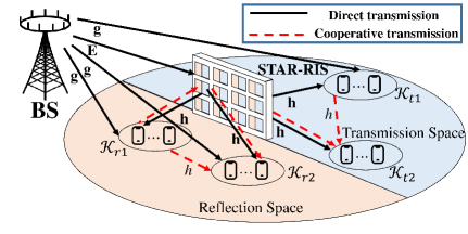
As illustrated in Fig. 1, we consider a STAR RIS-assisted multi-user multiple-input single-output (MISO) downlink transmission network, with CRS supported during the transmission. There is a BS equipped with L𝐿L transmit antennas, a STAR RIS containing N𝑁N elements indexed by the set 𝒩={1,,N}𝒩1𝑁\mathcal{N}=\{1,\cdots,N\}, and K𝐾K users indexed by the set 𝒦={1,2,,K}𝒦12𝐾\mathcal{K}=\{1,2,\cdots,K\}. Each user is equipped with a single transmit antenna and a receive antenna. Given the ability of the STAR RIS to transmit and reflect the incident signal simultaneously, we divide the transmission space into two distinct subspaces, namely, the reflection space and the transmission space. Users in the reflection space receive signals reflected by the STAR RIS and are indexed by the set 𝒦rsubscript𝒦𝑟\mathcal{K}_{r}. Conversely, users in the transmission space receive signals transmitted by the STAR RIS and are indexed by the set 𝒦tsubscript𝒦𝑡\mathcal{K}_{t}. The two user sets satisfy 𝒦r𝒦t=𝒦subscript𝒦𝑟subscript𝒦𝑡𝒦\mathcal{K}_{r}\cup\mathcal{K}_{t}=\mathcal{K} and 𝒦r𝒦t=subscript𝒦𝑟subscript𝒦𝑡\mathcal{K}_{r}\cap\mathcal{K}_{t}=\emptyset. Both subspaces allow user relaying, which further divides the users in each subspace into two user groups: the relaying user group 𝒦i1subscript𝒦𝑖1\mathcal{K}_{i1} and the destination user group 𝒦i2,i{r,t}subscript𝒦𝑖2𝑖𝑟𝑡\mathcal{K}_{i2},i\in\{r,t\}. The user groups satisfy 𝒦r1𝒦r2=,𝒦t1𝒦t2=formulae-sequencesubscript𝒦𝑟1subscript𝒦𝑟2subscript𝒦𝑡1subscript𝒦𝑡2\mathcal{K}_{r1}\cap\mathcal{K}_{r2}=\emptyset,\mathcal{K}_{t1}\cap\mathcal{K}_{t2}=\emptyset, 𝒦r1𝒦r2=𝒦rsubscript𝒦𝑟1subscript𝒦𝑟2subscript𝒦𝑟\mathcal{K}_{r1}\cup\mathcal{K}_{r2}=\mathcal{K}_{r}, and 𝒦t1𝒦t2=𝒦tsubscript𝒦𝑡1subscript𝒦𝑡2subscript𝒦𝑡\mathcal{K}_{t1}\cup\mathcal{K}_{t2}=\mathcal{K}_{t}. For simplicity, we denote the relaying user set and the destination user set in the full space as 𝒦1=𝒦t1𝒦r1subscript𝒦1subscript𝒦𝑡1subscript𝒦𝑟1\mathcal{K}_{1}=\mathcal{K}_{t1}\cup\mathcal{K}_{r1} and 𝒦2=𝒦t2𝒦r2subscript𝒦2subscript𝒦𝑡2subscript𝒦𝑟2\mathcal{K}_{2}=\mathcal{K}_{t2}\cup\mathcal{K}_{r2}, respectively. Without loss of generality, we assume users in 𝒦1subscript𝒦1\mathcal{K}_{1} have better channel conditions than users in 𝒦2subscript𝒦2\mathcal{K}_{2}.

In this work, we consider a block-fading channel model with T𝑇T transmission blocks indexed by the set 𝒯={1,,T}𝒯1𝑇\mathcal{T}=\{1,\cdots,T\}. The channels between the BS and STAR RIS, the BS and user-k𝑘k, STAR RIS and user-k𝑘k are respectively denoted by 𝐄(t)N×L,𝐠k(t)L×1formulae-sequence𝐄𝑡superscript𝑁𝐿subscript𝐠𝑘𝑡superscript𝐿1\mathbf{E}(t)\,\in\,\mathbb{C}^{N\times L},\,\mathbf{g}_{k}(t)\,\in\,\mathbb{C}^{L\times 1}, 𝐡k(t)N×1subscript𝐡𝑘𝑡superscript𝑁1\mathbf{h}_{k}(t)\,\in\,\mathbb{C}^{N\times 1}, where t𝑡t denotes the t𝑡t-th block, t𝒯𝑡𝒯t\in\mathcal{T}. Besides, the channel between user-i𝑖i to user-j𝑗j is denoted by hi,jsubscript𝑖𝑗h_{i,j}. As the pioneer study on STAR RIS-empowered CRS, we employ a simplified CSI model by assuming perfect knowledge of CSI at the BS for all communication links, i.e., perfect CSI at the transmitter (CSIT). The imperfect CSIT setting can be easily extended based on the existing works on RSMA with imperfect CSIT. It’s important to highlight that our primary emphasis is on exploring the diverse performance achieved by various transmission modes of STAR RIS-empowered CRS.

Refer to caption

Figure 1: The transmission architecture of the proposed STAR RIS-assisted CRS.

II-A Transmission Modes of STAR RIS-empowered CRS

CRS involves two transmission phases: the direct transmission phase and the cooperative transmission phase. During the direct transmission phase, the BS sends signals to all users. In the cooperative transmission phase, users in 𝒦1subscript𝒦1\mathcal{K}_{1} act as relaying users to transmit the decoded common stream to users in 𝒦2subscript𝒦2\mathcal{K}_{2}, utilizing either the HD or FD protocols. The FD protocol allows simultaneous transmission and reception for relaying users. However, this approach introduces self-interference at the relaying users. In the HD protocol, each time block is divided into two consecutive parts respectively for the two transmission phases. Let λ𝜆\lambda (0<λ1)0𝜆1(0<\lambda\leq 1) denote the fraction of time allocated to the direct transmission phase, and (1λ)1𝜆(1-\lambda) is the fraction allocated to the cooperative transmission phase.

In this paper, both transmission phases of CRS are assisted by the STAR RIS. According to the principle of single connected STAR RIS in [13], each element of STAR RIS can operate in the reflection mode and/or the transmission mode according to different operating protocols [13]. The reflection and transmission matrices are all diagonal matrices, denoted as 𝚯i=diag(β1,iejθ1,i,,βN,iejθN,i)subscript𝚯𝑖diagsubscript𝛽1𝑖superscript𝑒𝑗subscript𝜃1𝑖subscript𝛽𝑁𝑖superscript𝑒𝑗subscript𝜃𝑁𝑖\bm{\Theta}_{i}=\text{diag}\left(\sqrt{\beta_{1,i}}e^{j\theta_{1,i}},\cdots,\sqrt{\beta_{N,i}}e^{j\theta_{N,i}}\right), i{r,t}𝑖𝑟𝑡i\in\{r,t\}. In the ES protocol, each element of STAR RIS simultaneously reflects and transmits the incident signal. Hence, βn,rsubscript𝛽𝑛𝑟\beta_{n,r} and βn,tsubscript𝛽𝑛𝑡\beta_{n,t} should satisfy βn,r+βn,t=1subscript𝛽𝑛𝑟subscript𝛽𝑛𝑡1\beta_{n,r}+\beta_{n,t}=1 and βn,r,βn,t[0,1]subscript𝛽𝑛𝑟subscript𝛽𝑛𝑡01\beta_{n,r},\beta_{n,t}\in[0,1]. The MS protocol is a special case of ES where each element operates in either reflection or transmission mode, resulting in binary values for the amplitude coefficients, i.e., βn,r,βn,t0,1formulae-sequencesubscript𝛽𝑛𝑟subscript𝛽𝑛𝑡01\beta_{n,r},\beta_{n,t}\in{0,1}. In the TS protocol, each element of STAR RIS switches between the transmission and reflection modes in each transmission block. Define 0λr10subscript𝜆𝑟10\leq\lambda_{r}\leq 1 as the percentage of time allocated to the reflection mode in each transmission block, (1λr)1subscript𝜆𝑟(1-\lambda_{r}) as the percentage of time allocated to the transmission mode. The TS protocol focuses on designing λrsubscript𝜆𝑟\lambda_{r} and the phase shifts, where βn,r=1,βn,t=0formulae-sequencesubscript𝛽𝑛𝑟1subscript𝛽𝑛𝑡0\beta_{n,r}=1,\beta_{n,t}=0 during the λrsubscript𝜆𝑟\lambda_{r} percentage of time and βn,r=0,βn,t=1formulae-sequencesubscript𝛽𝑛𝑟0subscript𝛽𝑛𝑡1\beta_{n,r}=0,\beta_{n,t}=1 for the remaining (1λr)1subscript𝜆𝑟(1-\lambda_{r}).

Refer to caption

Figure 2: Six transmission modes of the proposed STAR RIS-assisted CRS.

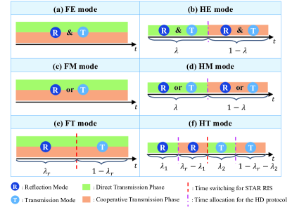
In the proposed STAR RIS-assisted CRS transmission framework, we pair the aforementioned relaying protocols (HD and FD) with the three STAR RIS operating protocols (ES, MS, and TS), yielding six distinct transmission modes for STAR RIS-assisted CRS. These modes are summarized in Fig. 2 and explained as follows:

  • FD-ES (FE) mode: This refers to the use of the HD protocol for CRS and the ES protocol for the STAR RIS. As illustrated in Fig. 2(a), HE enables each element of the STAR RIS to operate in both transmission and reflection modes simultaneously in the non-orthogonal direct and cooperative transmission phases.

  • HD-ES (HE) mode: This refers to the use of the HD protocol for CRS and the ES protocol for the STAR RIS. As illustrated in Fig. 2(b), HE enables each element of the STAR RIS to operate in both transmission and reflection modes simultaneously in the orthogonal direct and cooperative transmission phases.

  • FD-MS (FM) mode: This refers to the use of the FD protocol for CRS and the MS protocol for the STAR RIS. As illustrated in Fig. 2(c), FM enables each element of the STAR RIS to operate in either transmission or reflection mode in the non-orthogonal direct and cooperative transmission phases.

  • HD-MS (HM) mode: This refers to the use of the HD protocol for CRS and the MS protocol for the STAR RIS. As illustrated in Fig. 2(d), HM enables each element of the STAR RIS to operate in either transmission or reflection mode in the orthogonal direct and cooperative transmission phases.

  • FD-TS (FT) mode: This refers to the use of the FD protocol for CRS and the TS protocol for the STAR RIS. As illustrated in Fig. 2(e), each transmission block is split into two time slots based on λrsubscript𝜆𝑟\lambda_{r} (0λr10subscript𝜆𝑟10\leq\lambda_{r}\leq 1). FT facilitates all elements of the STAR RIS to function in the reflection mode during the initial portion λrsubscript𝜆𝑟\lambda_{r} of the time, while they operate in the transmission mode during the subsequent portion 1λr1subscript𝜆𝑟1-\lambda_{r} of the time, across the non-orthogonal direct and cooperative transmission phases.

  • HD-TS (HT) mode: This refers to the use of the HD protocol for CRS and the TS protocol for the STAR RIS. As illustrated in Fig. 2(f), each transmission block is split into two time slots based on λrsubscript𝜆𝑟\lambda_{r}: one for the reflection mode and the other for the transmission mode of STAR RIS. Then, each time slot is further split into two orthogonal parts for the direct and cooperative transmission phases of CRS, resulting in a total of four orthogonal transmission slots. Here, we introduce λ1subscript𝜆1\lambda_{1} (0<λ1λr0subscript𝜆1subscript𝜆𝑟0<\lambda_{1}\leq\lambda_{r}) and λ2subscript𝜆2\lambda_{2} (0<λ21λr0subscript𝜆21subscript𝜆𝑟0<\lambda_{2}\leq 1-\lambda_{r}) to represent the time allocation between the two transmission phases in the reflection and transmission modes, respectively.

Hereinafter, we use j𝑗j to represent the selected transmission mode, where j{FE,FM,FT,HE,HM,HT}𝑗FEFMFTHEHMHTj\in\{\mathrm{FE},\mathrm{FM},\mathrm{FT},\mathrm{HE},\mathrm{HM},\mathrm{HT}\}.

II-B Transmit Signal Model

For all six transmission modes described in the previous subsection, the primary differences among them lie in the received signals and the approaches employed to process the received signals. The transmit signals in both the direct and cooperative transmission phases remain consistent, as specified in this subsection.

II-B1 Direct transmission phase

We denote Wksubscript𝑊𝑘W_{k} as the message intended to user-k𝑘k. At the BS, according to the principle of 1-layer RSMA [21, 22], Wksubscript𝑊𝑘W_{k} is split into a common sub-message Wc,ksubscript𝑊𝑐𝑘W_{c,k} and a private sub-message Wp,ksubscript𝑊𝑝𝑘W_{p,k}. All common sub-messages Wc,1,,Wc,Ksubscript𝑊𝑐1subscript𝑊𝑐𝐾W_{c,1},\cdots,W_{c,K} are collected and then encoded into a common stream s0subscript𝑠0s_{0}, which is required to be decoded by all users. The individual private sub-message Wp,ksubscript𝑊𝑝𝑘W_{p,k} is independently encoded into a private stream sksubscript𝑠𝑘s_{k}, which is required to be decoded by user-k𝑘k only. Denote 𝐬=[s0,s1,,sK]T𝐬superscriptsubscript𝑠0subscript𝑠1subscript𝑠𝐾𝑇\mathbf{s}=[s_{0},s_{1},\ldots,s_{K}]^{T} and 𝐏=[𝐩0,𝐩1,,𝐩K]L×(K+1)𝐏subscript𝐩0subscript𝐩1subscript𝐩𝐾superscript𝐿𝐾1\mathbf{P}=[\mathbf{p}_{0},\mathbf{p}_{1},\ldots,\mathbf{p}_{K}]\in\mathbb{C}^{L\times(K+1)} respectively as the stream vector and the transmit beamforming matrix, where 𝐩kL×1subscript𝐩𝑘superscript𝐿1\mathbf{p}_{k}\in\mathbb{C}^{L\times 1}. The transmit signal at the BS in the direct transmission phase is given by

𝐱[1]=𝐏𝐬=k=0K𝐩ksk,superscript𝐱delimited-[]1𝐏𝐬superscriptsubscript𝑘0𝐾subscript𝐩𝑘subscript𝑠𝑘\small\mathbf{x}^{[1]}=\mathbf{P}\mathbf{s}=\sum_{k=0}^{K}\mathbf{p}_{k}s_{k}, (1)

where the superscript [1]delimited-[]1[1] denotes the direct transmission phase. Here, assuming 𝔼{𝐬𝐬H}=𝐈𝔼superscript𝐬𝐬𝐻𝐈\mathbb{E}\{\mathbf{s}\mathbf{s}^{H}\}=\mathbf{I}, the transmit power of the BS is limited by tr(𝐏𝐏H)Pttrsuperscript𝐏𝐏𝐻subscript𝑃𝑡\textrm{tr}(\mathbf{P}\mathbf{P}^{H})\leq P_{t}, where Ptsubscript𝑃𝑡P_{t} is the maximum transmit power at the BS.

II-B2 Cooperative transmission phase

Users in 𝒦1subscript𝒦1\mathcal{K}_{1} employ the decode-and-forward (DF) protocol to decode, re-encode, and subsequently transmit the decoded s0subscript𝑠0s_{0} to users in 𝒦2subscript𝒦2\mathcal{K}_{2}. The transmit signal at the relaying user-k𝑘k in the cooperative transmission phase is

xk[2]=Pks0,subscriptsuperscript𝑥delimited-[]2𝑘subscript𝑃𝑘subscript𝑠0x^{[2]}_{k}=\sqrt{P_{k}}s_{0}, (2)

where the superscript [2]delimited-[]2[2] denotes the cooperative transmission phase and Pksubscript𝑃𝑘P_{k} is the relaying transmit power at user-k𝑘k.

II-C Received Signal Model for FD-based Transmission Modes

In the FD-based transmission modes (FE, FM, and FT), both the direct and cooperative transmission phases share the same radio resources. Self-interference is inevitably among the relaying users in 𝒦1subscript𝒦1\mathcal{K}_{1} as they simultaneously receive signals from the BS and transmit the common stream s0subscript𝑠0s_{0} to users in 𝒦2subscript𝒦2\mathcal{K}_{2}, [23, 24]. We denote the self-interference channel as Ik(t)subscript𝐼𝑘𝑡I_{k}(t), which follows the same distribution Ik(t)𝒞𝒩(0,ΩI2)similar-tosubscript𝐼𝑘𝑡𝒞𝒩0superscriptsubscriptΩ𝐼2I_{k}(t)\sim\mathcal{CN}(0,\Omega_{I}^{2}) for all k𝒦1𝑘subscript𝒦1k\in\mathcal{K}_{1}. The signal received by users in 𝒦2subscript𝒦2\mathcal{K}_{2} from 𝒦1subscript𝒦1\mathcal{K}_{1}, denoted as s^0(t)subscript^𝑠0𝑡\hat{s}_{0}(t), is a delayed version of s0subscript𝑠0s_{0}, where s^0(t)=s0(ttd)subscript^𝑠0𝑡subscript𝑠0𝑡subscript𝑡𝑑\hat{s}_{0}(t)=s_{0}(t-t_{d}). Here, tdsubscript𝑡𝑑t_{d} represents the processing time for users in 𝒦1subscript𝒦1\mathcal{K}_{1} to decode and forward s0subscript𝑠0s_{0}. To ensure that the relaying users transmit and receive s^0(t)subscript^𝑠0𝑡\hat{s}_{0}(t) within the same block, we assume that tdsubscript𝑡𝑑t_{d} is much smaller than one block period [24, 25]. In this work, we focus on optimizing 𝐏𝐏\mathbf{P}, 𝚯rsubscript𝚯𝑟\bm{\Theta}_{r} and 𝚯tsubscript𝚯𝑡\bm{\Theta}_{t} in each transmission block. Hence, we omit t𝑡t in the following. Next, we will specify the received signals and achievable rates for FE, FM, and FT, respectively.

II-C1 FE/FM

When j=FE𝑗FEj=\mathrm{FE} or j=FM𝑗FMj=\mathrm{FM}, the signal received at each relaying user-k𝑘k in 𝒦1subscript𝒦1\mathcal{K}_{1} is given by

ykj=(𝐠kH+𝐡kH𝚯i𝐄)𝐠~k,iH𝐱[1]+IkPks^0+nk,i{r,t},formulae-sequencesubscriptsuperscript𝑦𝑗𝑘subscriptsuperscript~𝐠𝐻𝑘𝑖superscriptsubscript𝐠𝑘𝐻superscriptsubscript𝐡𝑘𝐻subscript𝚯𝑖𝐄superscript𝐱delimited-[]1subscript𝐼𝑘subscript𝑃𝑘subscript^𝑠0subscript𝑛𝑘𝑖𝑟𝑡\small\begin{split}y^{j}_{k}=\underset{\tilde{\mathbf{g}}^{H}_{k,i}}{\left(\underbrace{\mathbf{g}_{k}^{H}+\mathbf{h}_{k}^{H}\mathbf{\Theta}_{i}\mathbf{E}}\right)}\mathbf{x}^{[1]}+I_{k}\sqrt{P_{k}}\hat{s}_{0}+n_{k},i\in\{r,t\},\end{split} (3)

where nksubscript𝑛𝑘n_{k} is the additive white Gaussian noise (AWGN) which follows nk𝒞𝒩(0,σ2)similar-tosubscript𝑛𝑘𝒞𝒩0superscript𝜎2n_{k}\sim\mathcal{CN}(0,\sigma^{2}) and IkPks^0subscript𝐼𝑘subscript𝑃𝑘subscript^𝑠0I_{k}\sqrt{P}_{k}\hat{s}_{0} is the self-interference suffered at user-k𝑘k. Each user-k𝑘k in 𝒦1subscript𝒦1\mathcal{K}_{1} sequentially decodes the common stream s0subscript𝑠0s_{0} and the private stream sksubscript𝑠𝑘s_{k} with the assistance of SIC. Let 𝐠~k,isubscript~𝐠𝑘𝑖\tilde{\mathbf{g}}_{k,i} denote the effective channel between the BS and user-k𝑘k, the SINRs of decoding s0subscript𝑠0s_{0} and sksubscript𝑠𝑘s_{k} at user-k𝑘k in 𝒦1subscript𝒦1\mathcal{K}_{1} are respectively given as

γc,kFD=γc,kFD,[1]=|𝐠~k,iH𝐩0|2m𝒦|𝐠~k,iH𝐩m|2+|Ik|2Pk+σ2,subscriptsuperscript𝛾FD𝑐𝑘subscriptsuperscript𝛾FDdelimited-[]1𝑐𝑘superscriptsuperscriptsubscript~𝐠𝑘𝑖𝐻subscript𝐩02subscript𝑚𝒦superscriptsuperscriptsubscript~𝐠𝑘𝑖𝐻subscript𝐩𝑚2superscriptsubscript𝐼𝑘2subscript𝑃𝑘superscript𝜎2\displaystyle\gamma^{\mathrm{FD}}_{c,k}=\gamma^{\mathrm{FD},[1]}_{c,k}=\frac{\left|\mathbf{\tilde{g}}_{k,i}^{H}\mathbf{p}_{0}\right|^{2}}{\sum_{m\in\mathcal{K}}\left|\mathbf{\tilde{g}}_{k,i}^{H}\mathbf{p}_{m}\right|^{2}+\left|I_{k}\right|^{2}P_{k}+\sigma^{2}}, (4)
γkFD=|𝐠~k,iH𝐩k|2m𝒦,mk|𝐠~k,iH𝐩m|2+|Ik|2Pk+σ2.subscriptsuperscript𝛾FD𝑘superscriptsuperscriptsubscript~𝐠𝑘𝑖𝐻subscript𝐩𝑘2subscriptformulae-sequence𝑚𝒦𝑚𝑘superscriptsuperscriptsubscript~𝐠𝑘𝑖𝐻subscript𝐩𝑚2superscriptsubscript𝐼𝑘2subscript𝑃𝑘superscript𝜎2\displaystyle\gamma^{\mathrm{FD}}_{k}=\frac{\left|\mathbf{\tilde{g}}_{k,i}^{H}\mathbf{p}_{k}\right|^{2}}{\sum_{m\in\mathcal{K},m\neq k}\left|\mathbf{\tilde{g}}_{k,i}^{H}\mathbf{p}_{m}\right|^{2}+\left|I_{k}\right|^{2}P_{k}+\sigma^{2}}. (5)

Each user-k𝑘k in 𝒦2subscript𝒦2\mathcal{K}_{2} receives signals from both the BS and the relaying users in 𝒦1subscript𝒦1\mathcal{K}_{1}, which is given as

ykj=𝐠~k,iH𝐱[1]+m𝒦1(hm,k+𝐡kH𝚯iH𝐡m)h~m,k,ixm[2]+nk,i{r,t}.formulae-sequencesubscriptsuperscript𝑦𝑗𝑘superscriptsubscript~𝐠𝑘𝑖𝐻superscript𝐱delimited-[]1subscript𝑚subscript𝒦1subscript~𝑚𝑘𝑖subscript𝑚𝑘subscriptsuperscript𝐡𝐻𝑘superscriptsubscript𝚯𝑖𝐻subscript𝐡𝑚subscriptsuperscript𝑥delimited-[]2𝑚subscript𝑛𝑘𝑖𝑟𝑡\begin{split}y^{j}_{k}=\mathbf{\tilde{g}}_{k,i}^{H}\mathbf{x}^{[1]}+\sum_{m\in\mathcal{K}_{1}}\underset{\tilde{h}_{m,k,i}}{\left(\underbrace{h_{m,k}+\mathbf{h}^{H}_{k}\mathbf{\Theta}_{i}^{H}\mathbf{h}_{m}}\right)}x^{[2]}_{m}+n_{k},&\\ i\in\{r,t\}.&\end{split} (6)

Each user in 𝒦2subscript𝒦2\mathcal{K}_{2} then employs the maximal ratio combining (MRC) approach to ensure the received signals are properly co-phased and merged [26]. Denote the effective channel between user-m𝑚m and user-n𝑛n as h~m,n,isubscript~𝑚𝑛𝑖\tilde{h}_{m,n,i}, the SINRs of decoding the s0subscript𝑠0s_{0} and sksubscript𝑠𝑘s_{k} at user-k𝑘k in 𝒦2subscript𝒦2\mathcal{K}_{2} are given as

γc,kFD=|𝐠~k,iH𝐩0|2m𝒦|𝐠~k,iH𝐩m|2+σ2γc,kFD,[1]+m𝒦1|h~m,k,i|2Pmσ2γc,kFD,[2],subscriptsuperscript𝛾FD𝑐𝑘subscriptsuperscript𝛾FDdelimited-[]1𝑐𝑘superscriptsuperscriptsubscript~𝐠𝑘𝑖𝐻subscript𝐩02subscript𝑚𝒦superscriptsuperscriptsubscript~𝐠𝑘𝑖𝐻subscript𝐩𝑚2superscript𝜎2subscriptsuperscript𝛾FDdelimited-[]2𝑐𝑘subscript𝑚subscript𝒦1superscriptsubscript~𝑚𝑘𝑖2subscript𝑃𝑚superscript𝜎2\displaystyle\gamma^{\mathrm{FD}}_{c,k}=\underset{\gamma^{\mathrm{FD},[1]}_{c,k}}{\underbrace{\frac{\left|\mathbf{\tilde{g}}_{k,i}^{H}\mathbf{p}_{0}\right|^{2}}{\sum_{m\in\mathcal{K}}\left|\mathbf{\tilde{g}}_{k,i}^{H}\mathbf{p}_{m}\right|^{2}+\sigma^{2}}}}+\underset{\gamma^{\mathrm{FD},[2]}_{c,k}}{\underbrace{\frac{\sum_{m\in\mathcal{K}_{1}}\left|\tilde{h}_{m,k,i}\right|^{2}P_{m}}{\sigma^{2}}}}, (7)
γkFD=|𝐠~k,iH𝐩k|2m𝒦,mk|𝐠~k,iH𝐩m|2+σ2.subscriptsuperscript𝛾FD𝑘superscriptsuperscriptsubscript~𝐠𝑘𝑖𝐻subscript𝐩𝑘2subscriptformulae-sequence𝑚𝒦𝑚𝑘superscriptsuperscriptsubscript~𝐠𝑘𝑖𝐻subscript𝐩𝑚2superscript𝜎2\displaystyle\gamma^{\mathrm{FD}}_{k}=\frac{\left|\mathbf{\tilde{g}}_{k,i}^{H}\mathbf{p}_{k}\right|^{2}}{\sum_{m\in\mathcal{K},m\neq k}\left|\mathbf{\tilde{g}}_{k,i}^{H}\mathbf{p}_{m}\right|^{2}+\sigma^{2}}. (8)

With the SINRs of s0subscript𝑠0s_{0} and sksubscript𝑠𝑘s_{k} in (4), (5), (7), and (8), the achievable common and private rates are obtained as Rc,kj=log2(1+γc,kFD)subscriptsuperscript𝑅𝑗𝑐𝑘subscript21subscriptsuperscript𝛾FD𝑐𝑘R^{j}_{c,k}=\log_{2}(1+\gamma^{\mathrm{FD}}_{c,k}) and Rkj=log2(1+γkFD)subscriptsuperscript𝑅𝑗𝑘subscript21subscriptsuperscript𝛾FD𝑘R^{j}_{k}=\log_{2}(1+\gamma^{\mathrm{FD}}_{k}), j{FE,FM}𝑗FEFMj\in\{\mathrm{FE},\mathrm{FM}\}. To guarantee all users decode the common stream, the following condition should satisfy [3]:

Rcj=min{Rc,kj|k𝒦},superscriptsubscript𝑅𝑐𝑗conditionalsuperscriptsubscript𝑅𝑐𝑘𝑗𝑘𝒦R_{c}^{j}=\min\{R_{c,k}^{j}|k\in\mathcal{K}\}, (9)

Rcjsuperscriptsubscript𝑅𝑐𝑗R_{c}^{j} is shared by all users, we denote Cksubscript𝐶𝑘C_{k} as the part of Rcjsuperscriptsubscript𝑅𝑐𝑗R_{c}^{j} that is allocated to user-k𝑘k, it satisfies k𝒦CkRcjsubscript𝑘𝒦subscript𝐶𝑘superscriptsubscript𝑅𝑐𝑗\sum_{k\in\mathcal{K}}C_{k}\leq R_{c}^{j}. Hence, the total achievable rate of user-k𝑘k is

Rtot,kj=Rkj+Ck,k𝒦.formulae-sequencesubscriptsuperscript𝑅𝑗𝑡𝑜𝑡𝑘subscriptsuperscript𝑅𝑗𝑘subscript𝐶𝑘for-all𝑘𝒦R^{j}_{tot,k}=R^{j}_{k}+C_{k},\forall k\in\mathcal{K}. (10)

Note that equations (9) and (10) remain applicable for other transmission modes by setting j𝑗j to FT/HE/HM/HTFTHEHMHT\mathrm{FT/HE/HM/HT}. In the following discussion of these transmission modes, the equations will not be repeated.

II-C2 FT

In FT mode, there are two time slots: all elements of STAR RIS operate in the reflection mode during the first time slot (λrsubscript𝜆𝑟\lambda_{r}) while all elements of STAR RIS operate in the transmission mode during the second time slot (1λr1subscript𝜆𝑟1-\lambda_{r}). We denote the SINRs for decoding s0subscript𝑠0s_{0} and sksubscript𝑠𝑘s_{k} in the reflection and transmission time slots respectively as γc,kFD,isubscriptsuperscript𝛾FD𝑖𝑐𝑘\gamma^{\mathrm{FD},i}_{c,k} and γkFD,isubscriptsuperscript𝛾FD𝑖𝑘\gamma^{\mathrm{FD},i}_{k}, where i{r,t}𝑖𝑟𝑡i\in\{r,t\}. In the reflection time slot, users in 𝒦rsubscript𝒦𝑟\mathcal{K}_{r} receives signal from the BS and the STAR RIS while users in 𝒦tsubscript𝒦𝑡\mathcal{K}_{t} receives signal from the BS only. The corresponding SINRs are given as

γc,kFD,rsubscriptsuperscript𝛾FD𝑟𝑐𝑘\displaystyle\gamma^{\mathrm{FD},r}_{c,k} =γc,kFD𝚯i=𝚯r,γkFD,r=γkFD𝚯i=𝚯r,k𝒦r,formulae-sequenceabsentevaluated-atsubscriptsuperscript𝛾FD𝑐𝑘subscript𝚯𝑖subscript𝚯𝑟formulae-sequencesubscriptsuperscript𝛾FD𝑟𝑘evaluated-atsubscriptsuperscript𝛾FD𝑘subscript𝚯𝑖subscript𝚯𝑟𝑘subscript𝒦𝑟\displaystyle=\gamma^{\mathrm{FD}}_{c,k}\mid_{\bm{\Theta}_{i}=\bm{\Theta}_{r}},\,\,\gamma^{\mathrm{FD},r}_{k}=\gamma^{\mathrm{FD}}_{k}\mid_{\bm{\Theta}_{i}=\bm{\Theta}_{r}},k\in\mathcal{K}_{r}, (11)
γc,kFD,rsubscriptsuperscript𝛾FD𝑟𝑐𝑘\displaystyle\gamma^{\mathrm{FD},r}_{c,k} =γc,kFD𝚯i=𝟎,γkFD,r=γkFD𝚯i=𝟎,k𝒦t,formulae-sequenceabsentevaluated-atsubscriptsuperscript𝛾FD𝑐𝑘subscript𝚯𝑖0formulae-sequencesubscriptsuperscript𝛾FD𝑟𝑘evaluated-atsubscriptsuperscript𝛾FD𝑘subscript𝚯𝑖0𝑘subscript𝒦𝑡\displaystyle=\gamma^{\mathrm{FD}}_{c,k}\mid_{\bm{\Theta}_{i}=\mathbf{0}},\,\,\gamma^{\mathrm{FD},r}_{k}=\gamma^{\mathrm{FD}}_{k}\mid_{\bm{\Theta}_{i}=\mathbf{0}},k\in\mathcal{K}_{t},

where γc,kFDsubscriptsuperscript𝛾FD𝑐𝑘\gamma^{\mathrm{FD}}_{c,k} and γkFDsubscriptsuperscript𝛾FD𝑘\gamma^{\mathrm{FD}}_{k} are defined in (4) and (5), respectively. In the transmission time slot, users in 𝒦rsubscript𝒦𝑟\mathcal{K}_{r} receives signal from the BS only while users in 𝒦tsubscript𝒦𝑡\mathcal{K}_{t} receives signal from both BS and STAR RIS. The corresponding SINRs are given as

γc,kFD,tsubscriptsuperscript𝛾FD𝑡𝑐𝑘\displaystyle\gamma^{\mathrm{FD},t}_{c,k} =γc,kFD𝚯i=𝟎,γkFD,t=γkFD𝚯i=𝟎,k𝒦r,formulae-sequenceabsentevaluated-atsubscriptsuperscript𝛾FD𝑐𝑘subscript𝚯𝑖0formulae-sequencesubscriptsuperscript𝛾FD𝑡𝑘evaluated-atsubscriptsuperscript𝛾FD𝑘subscript𝚯𝑖0𝑘subscript𝒦𝑟\displaystyle=\gamma^{\mathrm{FD}}_{c,k}\mid_{\bm{\Theta}_{i}=\mathbf{0}},\,\,\gamma^{\mathrm{FD},t}_{k}=\gamma^{\mathrm{FD}}_{k}\mid_{\bm{\Theta}_{i}=\mathbf{0}},k\in\mathcal{K}_{r}, (12)
γc,kFD,tsubscriptsuperscript𝛾FD𝑡𝑐𝑘\displaystyle\gamma^{\mathrm{FD},t}_{c,k} =γc,kFD𝚯i=𝚯t,γkFD,t=γkFD𝚯i=𝚯t,k𝒦tformulae-sequenceabsentevaluated-atsubscriptsuperscript𝛾FD𝑐𝑘subscript𝚯𝑖subscript𝚯𝑡formulae-sequencesubscriptsuperscript𝛾FD𝑡𝑘evaluated-atsubscriptsuperscript𝛾FD𝑘subscript𝚯𝑖subscript𝚯𝑡𝑘subscript𝒦𝑡\displaystyle=\gamma^{\mathrm{FD}}_{c,k}\mid_{\bm{\Theta}_{i}=\bm{\Theta}_{t}},\,\,\gamma^{\mathrm{FD},t}_{k}=\gamma^{\mathrm{FD}}_{k}\mid_{\bm{\Theta}_{i}=\bm{\Theta}_{t}},k\in\mathcal{K}_{t}

The achievable common and private rates for user-k𝑘k are given as

Rc,kFT=λrlog2(1+γc,kFD,r)+(1λr)log2(1+γc,kFD,t),RkFT=λrlog2(1+γkFD,r)+(1λr)log2(1+γkFD,t).formulae-sequencesubscriptsuperscript𝑅FT𝑐𝑘subscript𝜆𝑟subscript21subscriptsuperscript𝛾FD𝑟𝑐𝑘1subscript𝜆𝑟subscript21subscriptsuperscript𝛾FD𝑡𝑐𝑘subscriptsuperscript𝑅FT𝑘subscript𝜆𝑟subscript21subscriptsuperscript𝛾FD𝑟𝑘1subscript𝜆𝑟subscript21subscriptsuperscript𝛾FD𝑡𝑘\begin{split}R^{\mathrm{FT}}_{c,k}&=\lambda_{r}\log_{2}(1+\gamma^{\mathrm{FD},r}_{c,k})+(1-\lambda_{r})\log_{2}(1+\gamma^{\mathrm{FD},t}_{c,k}),\\ R^{\mathrm{FT}}_{k}&=\lambda_{r}\log_{2}(1+\gamma^{\mathrm{FD},r}_{k})+(1-\lambda_{r})\log_{2}(1+\gamma^{\mathrm{FD},t}_{k}).\end{split} (13)

By substituting Rc,kFTsubscriptsuperscript𝑅FT𝑐𝑘R^{\mathrm{FT}}_{c,k} and RkFTsubscriptsuperscript𝑅FT𝑘R^{\mathrm{FT}}_{k} into (9) and (10), we obtain the corresponding achievable rate of each user in the FT mode.

II-D Received Signal Model for HD-based Transmission Modes

In HD-based transmission modes, the direct and cooperative transmission phases are orthogonal in each transmission block. Contrast to FD-based modes, there is no self-interference at relaying users, but the transmission rates for the direct and transmission phases are scaled by the pre-log factors λ(0<λ1)𝜆0𝜆1\lambda(0<\lambda\leq 1) and (1λ)1𝜆(1-\lambda), respectively. In the following, we specify the received signals and achievable rates for HE, HM, and HT.

II-D1 HE/HM

In the direct transmission phase, the signal received at user-k𝑘k is

ykHD,[1]=𝐠~k,iH𝐱[1]+nk,k𝒦,j{HE,HM}.formulae-sequencesubscriptsuperscript𝑦HDdelimited-[]1𝑘subscriptsuperscript~𝐠𝐻𝑘𝑖superscript𝐱delimited-[]1subscript𝑛𝑘formulae-sequencefor-all𝑘𝒦𝑗HEHM\begin{split}y^{\mathrm{HD},[1]}_{k}=\mathbf{\tilde{g}}^{H}_{k,i}\mathbf{x}^{[1]}+n_{k},\forall k\in\mathcal{K},j\in\{\mathrm{HE},\mathrm{HM}\}.\end{split} (14)

The SINRs of decoding s0subscript𝑠0s_{0} and sksubscript𝑠𝑘s_{k} in the direct transmission phase are given as

γc,kHD,[1]=|𝐠~k,iH𝐩0|2m𝒦|𝐠~k,iH𝐩m|2+σ2,subscriptsuperscript𝛾HDdelimited-[]1𝑐𝑘superscriptsuperscriptsubscript~𝐠𝑘𝑖𝐻subscript𝐩02subscript𝑚𝒦superscriptsuperscriptsubscript~𝐠𝑘𝑖𝐻subscript𝐩𝑚2superscript𝜎2\displaystyle\gamma^{\mathrm{HD},[1]}_{c,k}=\frac{\left|\mathbf{\tilde{g}}_{k,i}^{H}\mathbf{p}_{0}\right|^{2}}{\sum_{m\in\mathcal{K}}\left|\mathbf{\tilde{g}}_{k,i}^{H}\mathbf{p}_{m}\right|^{2}+\sigma^{2}}, (15)
γkHD=|𝐠~k,iH𝐩0|2m𝒦,mk|𝐠~k,iH𝐩m|2+σ2.subscriptsuperscript𝛾HD𝑘superscriptsuperscriptsubscript~𝐠𝑘𝑖𝐻subscript𝐩02subscriptformulae-sequence𝑚𝒦𝑚𝑘superscriptsuperscriptsubscript~𝐠𝑘𝑖𝐻subscript𝐩𝑚2superscript𝜎2\displaystyle\gamma^{\mathrm{HD}}_{k}=\frac{\left|\mathbf{\tilde{g}}_{k,i}^{H}\mathbf{p}_{0}\right|^{2}}{\sum_{m\in\mathcal{K},m\neq k}\left|\mathbf{\tilde{g}}_{k,i}^{H}\mathbf{p}_{m}\right|^{2}+\sigma^{2}}. (16)

In the cooperative transmission phase, users in 𝒦1subscript𝒦1\mathcal{K}_{1} forward the decoded s0subscript𝑠0s_{0} to users in 𝒦2subscript𝒦2\mathcal{K}_{2}. The signal received at user-k𝑘k in 𝒦2subscript𝒦2\mathcal{K}_{2} in the cooperative transmission phase is

ykHD,[2]=m𝒦1h~m,k,iPms0+nk,k𝒦2.formulae-sequencesubscriptsuperscript𝑦HDdelimited-[]2𝑘subscript𝑚subscript𝒦1subscript~𝑚𝑘𝑖subscript𝑃𝑚subscript𝑠0subscript𝑛𝑘for-all𝑘subscript𝒦2\displaystyle y^{\mathrm{HD},[2]}_{k}=\sum_{m\in\mathcal{K}_{1}}\tilde{h}_{m,k,i}\sqrt{P_{m}}s_{0}+n_{k},\forall k\in\mathcal{K}_{2}. (17)

The SINR of decoding s0subscript𝑠0s_{0} at user-k𝑘k in 𝒦2subscript𝒦2\mathcal{K}_{2} in the cooperative transmission phase is given as

γc,kHD,[2]=m𝒦1|h~m,k,i|2Pmσ2.subscriptsuperscript𝛾HDdelimited-[]2𝑐𝑘subscript𝑚subscript𝒦1superscriptsubscript~𝑚𝑘𝑖2subscript𝑃𝑚superscript𝜎2\displaystyle\gamma^{\mathrm{HD},[2]}_{c,k}=\frac{\sum_{m\in\mathcal{K}_{1}}\left|\tilde{h}_{m,k,i}\right|^{2}P_{m}}{\sigma^{2}}. (18)

With the SINR in (15), (16), and (18), we obtain the achievable common and private rates in HF and HM modes (jHE/HM𝑗HEHMj\in\mathrm{HE}/\mathrm{HM}) as

Rc,kjsubscriptsuperscript𝑅𝑗𝑐𝑘\displaystyle R^{j}_{c,k} =λlog2(1+γc,kHD,[1]),k𝒦1formulae-sequenceabsent𝜆subscript21subscriptsuperscript𝛾HDdelimited-[]1𝑐𝑘for-all𝑘subscript𝒦1\displaystyle=\lambda\log_{2}\left(1+\gamma^{\mathrm{HD},[1]}_{c,k}\right),\forall k\in\mathcal{K}_{1} (19)
Rc,kjsubscriptsuperscript𝑅𝑗𝑐𝑘\displaystyle R^{j}_{c,k} =λlog2(1+γc,kHD,[1])+(1λ)log2(1+γc,kHD,[2]),k𝒦2formulae-sequenceabsent𝜆subscript21subscriptsuperscript𝛾HDdelimited-[]1𝑐𝑘1𝜆subscript21subscriptsuperscript𝛾HDdelimited-[]2𝑐𝑘for-all𝑘subscript𝒦2\displaystyle=\lambda\log_{2}\left(1+\gamma^{\mathrm{HD},[1]}_{c,k}\right)+(1-\lambda)\log_{2}\left(1+\gamma^{\mathrm{HD},[2]}_{c,k}\right),\forall k\in\mathcal{K}_{2}

and

Rkj=λlog2(1+γkHD).subscriptsuperscript𝑅𝑗𝑘𝜆subscript21subscriptsuperscript𝛾HD𝑘R^{j}_{k}=\lambda\log_{2}\left(1+\gamma^{\mathrm{HD}}_{k}\right). (20)

By substituting (19) and (20) into (9) and (10), we obtain the corresponding achievable rate of each user in the HE and HM modes.

II-D2 HT

In the HT mode, there are four time slots: two for direct transmission with STAR RIS reflection or transmission, and two for cooperative transmission with STAR RIS reflection or transmission. We use γc,kHD,[s],isubscriptsuperscript𝛾HDdelimited-[]𝑠𝑖𝑐𝑘\gamma^{\mathrm{HD},[s],i}_{c,k} and γkHD,isubscriptsuperscript𝛾HD𝑖𝑘\gamma^{\mathrm{HD},i}_{k}, i{r,t}𝑖𝑟𝑡i\in\{r,t\}, s{1,2}𝑠12s\in\{1,2\} to denote the SINRs of decoding s0subscript𝑠0s_{0} and sksubscript𝑠𝑘s_{k} in the direct or cooperative transmission phase. The superscript i𝑖i indicates whether it’s in the reflection or transmission time slot. Specifically, in the two reflection time slots respectively for cooperative and transmission phases, we have

γc,kHD,[s],rsubscriptsuperscript𝛾HDdelimited-[]𝑠𝑟𝑐𝑘\displaystyle\gamma^{\mathrm{HD},[s],r}_{c,k} =γc,kHD,[s]𝚯i=𝚯r,γkHD,r=γkHD𝚯i=𝚯r,k𝒦r,formulae-sequenceabsentevaluated-atsubscriptsuperscript𝛾HDdelimited-[]𝑠𝑐𝑘subscript𝚯𝑖subscript𝚯𝑟formulae-sequencesubscriptsuperscript𝛾HD𝑟𝑘evaluated-atsubscriptsuperscript𝛾HD𝑘subscript𝚯𝑖subscript𝚯𝑟𝑘subscript𝒦𝑟\displaystyle=\gamma^{\mathrm{HD},[s]}_{c,k}\mid_{\bm{\Theta}_{i}=\bm{\Theta}_{r}},\,\,\gamma^{\mathrm{HD},r}_{k}=\gamma^{\mathrm{HD}}_{k}\mid_{\bm{\Theta}_{i}=\bm{\Theta}_{r}},k\in\mathcal{K}_{r}, (21)
γc,kHD,[s],rsubscriptsuperscript𝛾HDdelimited-[]𝑠𝑟𝑐𝑘\displaystyle\gamma^{\mathrm{HD},[s],r}_{c,k} =γc,kHD,[s]𝚯i=𝟎,γkHD,r=γkHD𝚯i=𝟎,k𝒦t,formulae-sequenceabsentevaluated-atsubscriptsuperscript𝛾HDdelimited-[]𝑠𝑐𝑘subscript𝚯𝑖0formulae-sequencesubscriptsuperscript𝛾HD𝑟𝑘evaluated-atsubscriptsuperscript𝛾HD𝑘subscript𝚯𝑖0𝑘subscript𝒦𝑡\displaystyle=\gamma^{\mathrm{HD},[s]}_{c,k}\mid_{\bm{\Theta}_{i}=\mathbf{0}},\,\,\gamma^{\mathrm{HD},r}_{k}=\gamma^{\mathrm{HD}}_{k}\mid_{\bm{\Theta}_{i}=\mathbf{0}},k\in\mathcal{K}_{t},

where γc,kHD,[s],s{1,2}subscriptsuperscript𝛾HDdelimited-[]𝑠𝑐𝑘𝑠12\gamma^{\mathrm{HD},[s]}_{c,k},s\in\{1,2\} and γkFDsubscriptsuperscript𝛾FD𝑘\gamma^{\mathrm{FD}}_{k} are defined in (15), (18), and (16), and respectively. In the two transmission time slots respectively for cooperative and transmission phases, we have

γc,kHD,[s],tsubscriptsuperscript𝛾HDdelimited-[]𝑠𝑡𝑐𝑘\displaystyle\gamma^{\mathrm{HD},[s],t}_{c,k} =γc,kHD,[s]𝚯i=𝟎,γkHD,t=γkHD𝚯i=𝟎,k𝒦r,formulae-sequenceabsentevaluated-atsubscriptsuperscript𝛾HDdelimited-[]𝑠𝑐𝑘subscript𝚯𝑖0formulae-sequencesubscriptsuperscript𝛾HD𝑡𝑘evaluated-atsubscriptsuperscript𝛾HD𝑘subscript𝚯𝑖0𝑘subscript𝒦𝑟\displaystyle=\gamma^{\mathrm{HD},[s]}_{c,k}\mid_{\bm{\Theta}_{i}=\mathbf{0}},\,\,\gamma^{\mathrm{HD},t}_{k}=\gamma^{\mathrm{HD}}_{k}\mid_{\bm{\Theta}_{i}=\mathbf{0}},k\in\mathcal{K}_{r}, (22)
γc,kHD,[s],tsubscriptsuperscript𝛾HDdelimited-[]𝑠𝑡𝑐𝑘\displaystyle\gamma^{\mathrm{HD},[s],t}_{c,k} =γc,kHD,[s]𝚯i=𝚯t,γkHD,t=γkHD𝚯i=𝚯t,k𝒦t.formulae-sequenceabsentevaluated-atsubscriptsuperscript𝛾HDdelimited-[]𝑠𝑐𝑘subscript𝚯𝑖subscript𝚯𝑡formulae-sequencesubscriptsuperscript𝛾HD𝑡𝑘evaluated-atsubscriptsuperscript𝛾HD𝑘subscript𝚯𝑖subscript𝚯𝑡𝑘subscript𝒦𝑡\displaystyle=\gamma^{\mathrm{HD},[s]}_{c,k}\mid_{\bm{\Theta}_{i}=\bm{\Theta}_{t}},\,\,\gamma^{\mathrm{HD},t}_{k}=\gamma^{\mathrm{HD}}_{k}\mid_{\bm{\Theta}_{i}=\bm{\Theta}_{t}},k\in\mathcal{K}_{t}.

Hence, the achievable common and private rates for user-k𝑘k are given as

Rc,kHTsubscriptsuperscript𝑅HT𝑐𝑘\displaystyle R^{\mathrm{HT}}_{c,k} =λ1log2(1+γc,kHD,[1],r)+λ2log2(1+γc,kHD,[1],t),absentsubscript𝜆1subscript21subscriptsuperscript𝛾HDdelimited-[]1𝑟𝑐𝑘subscript𝜆2subscript21subscriptsuperscript𝛾HDdelimited-[]1𝑡𝑐𝑘\displaystyle=\lambda_{1}\log_{2}\left(1+\gamma^{\mathrm{HD},[1],r}_{c,k}\right)+\lambda_{2}\log_{2}\left(1+\gamma^{\mathrm{HD},[1],t}_{c,k}\right), (23)
k𝒦1,for-all𝑘subscript𝒦1\displaystyle\quad\quad\quad\quad\quad\quad\quad\quad\quad\quad\quad\quad\quad\quad\quad\quad\quad\forall k\in\mathcal{K}_{1},
Rc,kHTsubscriptsuperscript𝑅HT𝑐𝑘\displaystyle R^{\mathrm{HT}}_{c,k} =λ1log2(1+γc,kHD,[1],r)absentsubscript𝜆1subscript21subscriptsuperscript𝛾HDdelimited-[]1𝑟𝑐𝑘\displaystyle=\lambda_{1}\log_{2}\left(1+\gamma^{\mathrm{HD},[1],r}_{c,k}\right)
+(λrλ1)log2(1+γc,kHD,[2],r)subscript𝜆𝑟subscript𝜆1subscript21subscriptsuperscript𝛾HDdelimited-[]2𝑟𝑐𝑘\displaystyle+(\lambda_{r}-\lambda_{1})\log_{2}\left(1+\gamma^{\mathrm{HD},[2],r}_{c,k}\right)
+λ2log2(1+γc,kHD,[1],t)subscript𝜆2subscript21subscriptsuperscript𝛾HDdelimited-[]1𝑡𝑐𝑘\displaystyle+\lambda_{2}\log_{2}\left(1+\gamma^{\mathrm{HD},[1],t}_{c,k}\right)
+(1λrλ2)log2(1+γc,kHD,[2],t),k𝒦2.1subscript𝜆𝑟subscript𝜆2subscript21subscriptsuperscript𝛾HDdelimited-[]2𝑡𝑐𝑘for-all𝑘subscript𝒦2\displaystyle+(1-\lambda_{r}-\lambda_{2})\log_{2}\left(1+\gamma^{\mathrm{HD},[2],t}_{c,k}\right),\quad\forall k\in\mathcal{K}_{2}.
RkHT=λ1log2(1+γkHD,r)+λ2log2(1+γkHD,t).subscriptsuperscript𝑅HT𝑘subscript𝜆1subscript21subscriptsuperscript𝛾HD𝑟𝑘subscript𝜆2subscript21subscriptsuperscript𝛾HD𝑡𝑘R^{\mathrm{HT}}_{k}=\lambda_{1}\log_{2}\left(1+\gamma^{\mathrm{HD},r}_{k}\right)+\lambda_{2}\log_{2}\left(1+\gamma^{\mathrm{HD},t}_{k}\right). (24)

II-E Problem Formulation

In this work, we aim to jointly optimize the active beamforming 𝐏𝐏\mathbf{P} at the BS, the common rate allocation 𝐜=[C1,,CK]𝐜subscript𝐶1subscript𝐶𝐾\mathbf{c}=[C_{1},\cdots,C_{K}], as well as the passive beamforming 𝚯rsubscript𝚯𝑟\bm{\Theta}_{r}, 𝚯tsubscript𝚯𝑡\bm{\Theta}_{t} at the STAR RIS. For the HD-based transmission modes, the corresponding time allocation coefficients are also jointly optimized. Our objective is to maximize the minimum user rate (max-min rate) among all users subject to the transmit power constraint. The formulated problems for the six transmission modes of the proposed STAR RIS-aided CRS model are illustrated as follows:

II-E1 FE

j=FE𝑗FEj=\mathrm{FE}, the optimization problem is formulated as

𝒫FE::subscript𝒫FEabsent\displaystyle\mathcal{P}_{\mathrm{FE}}:\,\,\,\, max𝐏,𝐜,𝚯r,𝚯tmink𝒦Rtot,kFEsubscript𝐏𝐜subscript𝚯𝑟subscript𝚯𝑡subscript𝑘𝒦subscriptsuperscript𝑅FE𝑡𝑜𝑡𝑘\displaystyle\max_{\mathbf{P},\mathbf{c},\bm{\Theta}_{r},\bm{\Theta}_{t}}\,\,\min_{k\in\mathcal{K}}\,\,R^{\mathrm{FE}}_{tot,k} (25a)
s.t. k𝒦CkRcj,Ck0,k𝒦formulae-sequencesubscript𝑘𝒦subscript𝐶𝑘subscriptsuperscript𝑅𝑗𝑐formulae-sequencesubscript𝐶𝑘0for-all𝑘𝒦\displaystyle\sum_{k\in\mathcal{K}}C_{k}\leq R^{j}_{c},C_{k}\geq 0,\forall k\in\mathcal{K} (25b)
θn,i[0,2π),n𝒩,i{r,t},formulae-sequencesubscript𝜃𝑛𝑖02𝜋formulae-sequencefor-all𝑛𝒩𝑖𝑟𝑡\displaystyle\theta_{n,i}\in[0,2\pi),\forall n\in\mathcal{N},i\in\{r,t\}, (25c)
tr(𝐏𝐏H)Pttrsuperscript𝐏𝐏𝐻subscript𝑃𝑡\displaystyle\text{tr}\left(\mathbf{P}\mathbf{P}^{H}\right)\leq P_{t} (25d)
βn,r,βn,t[0,1],βn,r+βn,t=1,n𝒩,formulae-sequencesubscript𝛽𝑛𝑟subscript𝛽𝑛𝑡01formulae-sequencesubscript𝛽𝑛𝑟subscript𝛽𝑛𝑡1for-all𝑛𝒩\displaystyle\beta_{n,r},\beta_{n,t}\in[0,1],\beta_{n,r}+\beta_{n,t}=1,\forall n\in\mathcal{N}, (25e)

where constraint (25b) guarantees the common stream is successfully decoded by all users. Constraints (25c) and (25e) are the constraints for the phase shift and amplitude ranges for each element of the STAR RIS, respectively. (25d) limits the transmit power at the BS.

II-E2 FM

j=FM𝑗FMj=\mathrm{FM}, the formulated problem is given as

𝒫FM::subscript𝒫FMabsent\displaystyle\mathcal{P}_{\mathrm{FM}}:\,\,\,\, max𝐏,𝐜,𝚯r,𝚯tmink𝒦Rtot,kFMsubscript𝐏𝐜subscript𝚯𝑟subscript𝚯𝑡subscript𝑘𝒦subscriptsuperscript𝑅FM𝑡𝑜𝑡𝑘\displaystyle\max_{\mathbf{P},\mathbf{c},\bm{\Theta}_{r},\bm{\Theta}_{t}}\,\,\min_{k\in\mathcal{K}}\,\,R^{\mathrm{FM}}_{tot,k} (26a)
s.t. (25b)–(25d)
βn,r,βn,t{0,1},βn,r+βn,t=1,n𝒩.formulae-sequencesubscript𝛽𝑛𝑟subscript𝛽𝑛𝑡01formulae-sequencesubscript𝛽𝑛𝑟subscript𝛽𝑛𝑡1for-all𝑛𝒩\displaystyle\beta_{n,r},\beta_{n,t}\in\{0,1\},\beta_{n,r}+\beta_{n,t}=1,\forall n\in\mathcal{N}. (26b)

II-E3 FT

j=FT𝑗FTj=\mathrm{FT}, the time allocation variable λrsubscript𝜆𝑟\lambda_{r} is jointly optimized with the beamforming matrices and the common rate allocation. The optimization problem is

𝒫FT::subscript𝒫FTabsent\displaystyle\mathcal{P}_{\mathrm{FT}}:\,\,\,\, max𝐏,𝐜,𝚯r,𝚯t,λrmink𝒦Rtot,kFTsubscript𝐏𝐜subscript𝚯𝑟subscript𝚯𝑡subscript𝜆𝑟subscript𝑘𝒦subscriptsuperscript𝑅FT𝑡𝑜𝑡𝑘\displaystyle\max_{\mathbf{P},\mathbf{c},\bm{\Theta}_{r},\bm{\Theta}_{t},\lambda_{r}}\,\,\min_{k\in\mathcal{K}}\,\,R^{\mathrm{FT}}_{tot,k} (27a)
s.t. (25b)–(25d),
βn,r,βn,t[0,1],n𝒩,formulae-sequencesubscript𝛽𝑛𝑟subscript𝛽𝑛𝑡01for-all𝑛𝒩\displaystyle\beta_{n,r},\beta_{n,t}\in[0,1],\forall n\in\mathcal{N}, (27b)
0λr1.0subscript𝜆𝑟1\displaystyle 0\leq\lambda_{r}\leq 1. (27c)

II-E4 HE

j=HE𝑗HEj=\mathrm{HE}, the time allocation variable λ𝜆\lambda is jointly optimized with the beamforming matrices and the common rate allocation. The formulated problem is

𝒫HE::subscript𝒫HEabsent\displaystyle\mathcal{P}_{\mathrm{HE}}:\,\,\,\, max𝐏,𝐜,𝚯r,𝚯t,λmink𝒦Rtot,kHEsubscript𝐏𝐜subscript𝚯𝑟subscript𝚯𝑡𝜆subscript𝑘𝒦subscriptsuperscript𝑅HE𝑡𝑜𝑡𝑘\displaystyle\max_{\mathbf{P},\mathbf{c},\bm{\Theta}_{r},\bm{\Theta}_{t},\lambda}\,\,\min_{k\in\mathcal{K}}\,\,R^{\mathrm{HE}}_{tot,k} (28a)
s.t. (25b)–(25e)
0<λ1.0𝜆1\displaystyle 0<\lambda\leq 1. (28b)

II-E5 HM

j=HM𝑗HMj=\mathrm{HM}, the corresponding optimization problem is formulated as

𝒫HM::subscript𝒫HMabsent\displaystyle\mathcal{P}_{\mathrm{HM}}:\,\,\,\, max𝐏,𝐜,𝚯r,𝚯t,λmink𝒦Rtot,kHMsubscript𝐏𝐜subscript𝚯𝑟subscript𝚯𝑡𝜆subscript𝑘𝒦subscriptsuperscript𝑅HM𝑡𝑜𝑡𝑘\displaystyle\max_{\mathbf{P},\mathbf{c},\bm{\Theta}_{r},\bm{\Theta}_{t},\lambda}\,\,\min_{k\in\mathcal{K}}\,\,R^{\mathrm{HM}}_{tot,k} (29a)
s.t. (25b)–(25d), (26b), (28b).

II-E6 HT

j=HT𝑗HTj=\mathrm{HT}, λr,λ1,λ2subscript𝜆𝑟subscript𝜆1subscript𝜆2\lambda_{r},\lambda_{1},\lambda_{2} are jointly optimized. The corresponding optimization problem is formulated as

𝒫HT::subscript𝒫HTabsent\displaystyle\mathcal{P}_{\mathrm{HT}}:\,\,\,\, max𝐏,𝐜,𝚯r,𝚯t,λr,λ1,λ2mink𝒦Rtot,kHTsubscript𝐏𝐜subscript𝚯𝑟subscript𝚯𝑡subscript𝜆𝑟subscript𝜆1subscript𝜆2subscript𝑘𝒦subscriptsuperscript𝑅HT𝑡𝑜𝑡𝑘\displaystyle\max_{\mathbf{P},\mathbf{c},\bm{\Theta}_{r},\bm{\Theta}_{t},\lambda_{r},\lambda_{1},\lambda_{2}}\,\,\min_{k\in\mathcal{K}}\,\,R^{\mathrm{HT}}_{tot,k} (30a)
s.t. (25b)–(25d), (27b), (27c)
0<λ1λr,0<λ21λr.formulae-sequence0subscript𝜆1subscript𝜆𝑟0subscript𝜆21subscript𝜆𝑟\displaystyle 0<\lambda_{1}\leq\lambda_{r},0<\lambda_{2}\leq 1-\lambda_{r}. (30b)

From problems (25)-(30) for the six transmission modes, we observe that 𝐏𝐏\mathbf{P}, 𝚯rsubscript𝚯𝑟\bm{\Theta}_{r}, 𝚯tsubscript𝚯𝑡\bm{\Theta}_{t} are highly coupled in the non-convex and fractional expressions for the achievable common and private rates. Besides, problem (26) and (29) involve integer programming due to (25b). All problems are highly non-convex and difficult to solve. In the next section, we will propose two algorithm to solve the problems.

III Proposed Optimization Frameworks

To solve the aforementioned six non-convex optimization problems, in this section, we first propose an AO framework that alternatively optimizes the STAR RIS passive beamforming matrices 𝚯rsubscript𝚯𝑟\bm{\Theta}_{r} and 𝚯tsubscript𝚯𝑡\bm{\Theta}_{t}, and the remaining variables. To ease the computational complexity, we further propose a low-complexity algorithm to address the optimization problems.

III-A Proposed AO Algorithm

We divide the original non-convex problems into two subproblems, one for the STAR RIS passive beamforming design, the other for the joint BS active beamforming, common rate, and time allocation design. The approaches for solving the two subproblems are detailed in the following:

III-A1 STAR RIS passive beamforming optimization

With the transmit beamforming 𝐏𝐏\mathbf{P}, common rate allocation 𝐜𝐜\mathbf{c} and time allocation variables λtsubscript𝜆𝑡\lambda_{t}, λ1subscript𝜆1\lambda_{1} and λ2subscript𝜆2\lambda_{2} fixed, we focus on optimizing 𝚯rsubscript𝚯𝑟\bm{\Theta}_{r} and 𝚯tsubscript𝚯𝑡\bm{\Theta}_{t}. First, we introduce an auxiliary variable tjsuperscript𝑡𝑗t^{j} to represent the objective function for the transmission mode j𝑗j, leading to the following constraint:

Rp,kj+Cktj,k𝒦,j{FE,FM,FT,HE,HM,HT}.formulae-sequencesubscriptsuperscript𝑅𝑗𝑝𝑘subscript𝐶𝑘superscript𝑡𝑗formulae-sequencefor-all𝑘𝒦𝑗FEFMFTHEHMHTR^{j}_{p,k}+C_{k}\geq t^{j},\forall k\in\mathcal{K},j\in\{\mathrm{FE},\mathrm{FM},\mathrm{FT},\mathrm{HE},\mathrm{HM},\mathrm{HT}\}. (31)

Although the achievable rate expressions may vary across different transmission modes, our main focus is the SINR expressions as the optimization variables 𝚯rsubscript𝚯𝑟\bm{\Theta}_{r} and 𝚯tsubscript𝚯𝑡\bm{\Theta}_{t} are embedded solely within the SINR. Note that the non-convexity of the SINR expressions remains consistent across all six transmission modes. The key distinction in optimizing the STAR RIS across these modes lies in the constraints imposed by the ES, MS, and TS protocols.

In the following, we begin by illustrating the SCA-based method employed to address the non-convexity of the SINR expressions, using the FE mode as an example. Following this, we elaborate the penalty methods proposed to manage the STAR RIS constraints for the ES, MS, and TS protocols, respectively.

  • Step 1.1: The SCA method for non-convex SINRs:

Let ψn,i=βn,iejθn,i,n𝒩,i{r,t}formulae-sequencesubscript𝜓𝑛𝑖subscript𝛽𝑛𝑖superscript𝑒𝑗subscript𝜃𝑛𝑖formulae-sequence𝑛𝒩𝑖𝑟𝑡\psi_{n,i}=\sqrt{\beta_{n,i}}e^{j\theta_{n,i}},n\in\mathcal{N},i\in\{r,t\} denote each element of 𝚯rsubscript𝚯𝑟\bm{\Theta}_{r} and 𝚯tsubscript𝚯𝑡\bm{\Theta}_{t}. With 𝝍i=[ψ1,i,,ψN,i]Tsubscript𝝍𝑖superscriptsubscript𝜓1𝑖subscript𝜓𝑁𝑖𝑇\bm{\psi}_{i}=[\psi_{1,i},\ldots,\psi_{N,i}]^{T}, we have 𝐠kH𝐩m+𝐡kH𝚯i𝐄𝐩m=g¯km+𝐬kmH𝝍isuperscriptsubscript𝐠𝑘𝐻subscript𝐩𝑚superscriptsubscript𝐡𝑘𝐻subscript𝚯𝑖subscript𝐄𝐩𝑚subscript¯𝑔𝑘𝑚superscriptsubscript𝐬𝑘𝑚𝐻subscript𝝍𝑖\mathbf{g}_{k}^{H}\mathbf{p}_{m}+\mathbf{h}_{k}^{H}\mathbf{\Theta}_{i}\mathbf{E}\mathbf{p}_{m}=\bar{g}_{km}+\mathbf{s}_{km}^{H}\bm{\psi}_{i}, 𝐡nH𝚯i𝐡m=𝐡¯m,nH𝝍isuperscriptsubscript𝐡𝑛𝐻subscript𝚯𝑖subscript𝐡𝑚superscriptsubscript¯𝐡𝑚𝑛𝐻subscript𝝍𝑖\mathbf{h}_{n}^{H}\mathbf{\Theta}_{i}\mathbf{h}_{m}=\bar{\mathbf{h}}_{m,n}^{H}\bm{\psi}_{i}, where g¯km=𝐠kH𝐩msubscript¯𝑔𝑘𝑚superscriptsubscript𝐠𝑘𝐻subscript𝐩𝑚\bar{g}_{km}=\mathbf{g}_{k}^{H}\mathbf{p}_{m}, 𝐬km=(diag(𝐡kH)𝐄𝐩m)subscript𝐬𝑘𝑚superscriptdiagsuperscriptsubscript𝐡𝑘𝐻subscript𝐄𝐩𝑚\mathbf{s}_{km}=(\textrm{diag}(\mathbf{h}_{k}^{H})\mathbf{E}\mathbf{p}_{m})^{\ast} and 𝐡¯m,n=(diag(𝐡nH)𝐡m)N×1subscript¯𝐡𝑚𝑛superscriptdiagsuperscriptsubscript𝐡𝑛𝐻subscript𝐡𝑚superscript𝑁1\bar{\mathbf{h}}_{m,n}=(\textrm{diag}(\mathbf{h}_{n}^{H})\mathbf{h}_{m})^{\ast}\in\mathbb{C}^{N\times 1}. In this way, the optimization variables are represented by 𝝍rsubscript𝝍𝑟\bm{\psi}_{r} and 𝝍tsubscript𝝍𝑡\bm{\psi}_{t}.

Taking the FE problem (25) as an example, we first introduce slack variables 𝜹=[δ1,,δK]T𝜹superscriptsubscript𝛿1subscript𝛿𝐾𝑇\bm{\delta}=[\delta_{1},\ldots,\delta_{K}]^{T} and 𝜹c=[δc,1,,δc,K]Tsubscript𝜹𝑐superscriptsubscript𝛿𝑐1subscript𝛿𝑐𝐾𝑇\bm{\delta}_{c}=[\delta_{c,1},\ldots,\delta_{c,K}]^{T} to respectively denote the SINRs of sksubscript𝑠𝑘s_{k} and s0subscript𝑠0s_{0} in the direct transmission phase. Furthermore, we introduce 𝝃=[ξ1,,ξK2]𝝃subscript𝜉1subscript𝜉subscript𝐾2\bm{\xi}=[\xi_{1},\ldots,\xi_{K_{2}}] to denote the SINRs of the desination users in the cooperative transmission phase, where K2subscript𝐾2K_{2} is the number of users in 𝒦2subscript𝒦2\mathcal{K}_{2}. The optimization problem (25) for updating the STAR RIS passive beamforming matrices is then equivalently transformed into

𝒫FE1:subscript𝒫:FE1absent\displaystyle\mathcal{P}_{\mathrm{FE-1:}}\,\,\,\, maxtFE,𝝍r,𝝍t,𝜹,𝜹c,𝝃tFEsubscriptsuperscript𝑡FEsubscript𝝍𝑟subscript𝝍𝑡𝜹subscript𝜹𝑐𝝃superscript𝑡FE\displaystyle\max_{\begin{subarray}{c}t^{\mathrm{FE}},\bm{\psi}_{r},\bm{\psi}_{t},\bm{\delta},\bm{\delta}_{c},\bm{\xi}\end{subarray}}\,\,t^{\mathrm{FE}} (32a)
s.t. log2(1+δk)+CktFE,k𝒦,formulae-sequencesubscript21subscript𝛿𝑘subscript𝐶𝑘superscript𝑡FEfor-all𝑘𝒦\displaystyle\log_{2}(1+\delta_{k})+C_{k}\geq t^{\mathrm{FE}},\forall k\in\mathcal{K}, (32b)
log2(1+δc,k)m𝒦Cm,k𝒦1,formulae-sequencesubscript21subscript𝛿𝑐𝑘subscript𝑚𝒦subscript𝐶𝑚𝑘subscript𝒦1\displaystyle\log_{2}(1+\delta_{c,k})\geq{\textstyle\sum_{m\in\mathcal{K}}}C_{m},k\in\mathcal{K}_{1}, (32c)
log2(1+δc,k+ξk)m𝒦Cm,k𝒦2,formulae-sequencesubscript21subscript𝛿𝑐𝑘subscript𝜉𝑘subscript𝑚𝒦subscript𝐶𝑚𝑘subscript𝒦2\displaystyle\log_{2}(1+\delta_{c,k}+\xi_{k})\geq{\textstyle\sum_{m\in\mathcal{K}}}C_{m},k\in\mathcal{K}_{2}, (32d)
δc,kγc,kFD,[1],k𝒦,formulae-sequencesubscript𝛿𝑐𝑘subscriptsuperscript𝛾FDdelimited-[]1𝑐𝑘for-all𝑘𝒦\displaystyle\delta_{c,k}\leq\gamma^{\mathrm{FD},[1]}_{c,k},\forall k\in\mathcal{K}, (32e)
δkγkFD,k𝒦,formulae-sequencesubscript𝛿𝑘subscriptsuperscript𝛾FD𝑘for-all𝑘𝒦\displaystyle\delta_{k}\leq\gamma^{\mathrm{FD}}_{k},\forall k\in\mathcal{K}, (32f)
ξkγc,kFD,[2],k𝒦2,formulae-sequencesubscript𝜉𝑘subscriptsuperscript𝛾FDdelimited-[]2𝑐𝑘for-all𝑘subscript𝒦2\displaystyle\xi_{k}\leq\gamma^{\mathrm{FD},[2]}_{c,k},\forall k\in\mathcal{K}_{2}, (32g)
(25e).(25e)\displaystyle\text{(\ref{FD-ES:6})}.

For constraints (32e) and (32f), we further introduce slack variables 𝜼=[η1,,ηK]T𝜼superscriptsubscript𝜂1subscript𝜂𝐾𝑇\bm{\eta}=[\eta_{1},\ldots,\eta_{K}]^{T} and 𝜼c=[ηc,1,,ηc,K]Tsubscript𝜼𝑐superscriptsubscript𝜂𝑐1subscript𝜂𝑐𝐾𝑇\bm{\eta}_{c}=[\eta_{c,1},\ldots,\eta_{c,K}]^{T} to respectively denote the denominators of the SINRs for s0subscript𝑠0s_{0} and sksubscript𝑠𝑘s_{k}. (32e) and (32f) are equivalently transformed to

ηc,kde(γc,kFD,[1]),k𝒦formulae-sequencesubscript𝜂𝑐𝑘desubscriptsuperscript𝛾FDdelimited-[]1𝑐𝑘for-all𝑘𝒦\displaystyle\eta_{c,k}\geq\mathrm{de}(\gamma^{\mathrm{FD},[1]}_{c,k}),\forall k\in\mathcal{K} (33a)
ηkde(γkFD),k𝒦formulae-sequencesubscript𝜂𝑘desubscriptsuperscript𝛾FD𝑘for-all𝑘𝒦\displaystyle\eta_{k}\geq\mathrm{de}(\gamma^{\mathrm{FD}}_{k}),\forall k\in\mathcal{K} (33b)
δc,kηc,k|g¯k0+𝐬k0H𝝍i|2,subscript𝛿𝑐𝑘subscript𝜂𝑐𝑘superscriptsubscript¯𝑔𝑘0superscriptsubscript𝐬𝑘0𝐻subscript𝝍𝑖2\displaystyle\delta_{c,k}\eta_{c,k}\leq\left|\bar{g}_{k0}+\mathbf{s}_{k0}^{H}\bm{\psi}_{i}\right|^{2}, (33c)
δkηk|g¯kk+𝐬kkH𝝍i|2,subscript𝛿𝑘subscript𝜂𝑘superscriptsubscript¯𝑔𝑘𝑘superscriptsubscript𝐬𝑘𝑘𝐻subscript𝝍𝑖2\displaystyle\delta_{k}\eta_{k}\leq\left|\bar{g}_{kk}+\mathbf{s}_{kk}^{H}\bm{\psi}_{i}\right|^{2}, (33d)

where de()de\mathrm{de}(\cdot) is an operator defined to extract the denominator of a fraction, i.e., de(ab)=bde𝑎𝑏𝑏\mathrm{de}(\frac{a}{b})=b. For constraint (33c), the left-hand side (LHS) equals to δc,kηc,k=14(δc,k+ηc,k)214(δc,kηc,k)2subscript𝛿𝑐𝑘subscript𝜂𝑐𝑘14superscriptsubscript𝛿𝑐𝑘subscript𝜂𝑐𝑘214superscriptsubscript𝛿𝑐𝑘subscript𝜂𝑐𝑘2\delta_{c,k}\eta_{c,k}=\frac{1}{4}(\delta_{c,k}+\eta_{c,k})^{2}-\frac{1}{4}(\delta_{c,k}-\eta_{c,k})^{2}. By further approximating δc,kηc,ksubscript𝛿𝑐𝑘subscript𝜂𝑐𝑘\delta_{c,k}\eta_{c,k} at the point (δc,k[z],ηc,k[z])superscriptsubscript𝛿𝑐𝑘delimited-[]𝑧superscriptsubscript𝜂𝑐𝑘delimited-[]𝑧(\delta_{c,k}^{[z]},\eta_{c,k}^{[z]}) in iteration [z]delimited-[]𝑧[z] using the first-order Taylor approximation of (δc,kηc,k)2superscriptsubscript𝛿𝑐𝑘subscript𝜂𝑐𝑘2(\delta_{c,k}-\eta_{c,k})^{2}, we have

δc,kηc,k14(δc,k+ηc,k)212(δc,k[z]ηc,k[z])(δc,kηc,k)+14(δc,k[z]ηc,k[z])2ν(δc,k[z],ηc,k[z]).subscript𝛿𝑐𝑘subscript𝜂𝑐𝑘14superscriptsubscript𝛿𝑐𝑘subscript𝜂𝑐𝑘212superscriptsubscript𝛿𝑐𝑘delimited-[]𝑧superscriptsubscript𝜂𝑐𝑘delimited-[]𝑧subscript𝛿𝑐𝑘subscript𝜂𝑐𝑘14superscriptsuperscriptsubscript𝛿𝑐𝑘delimited-[]𝑧superscriptsubscript𝜂𝑐𝑘delimited-[]𝑧2𝜈superscriptsubscript𝛿𝑐𝑘delimited-[]𝑧superscriptsubscript𝜂𝑐𝑘delimited-[]𝑧\begin{split}\delta_{c,k}\eta_{c,k}\leq&\frac{1}{4}(\delta_{c,k}+\eta_{c,k})^{2}-\frac{1}{2}(\delta_{c,k}^{[z]}-\eta_{c,k}^{[z]})(\delta_{c,k}-\eta_{c,k})\\ &+\frac{1}{4}(\delta_{c,k}^{[z]}-\eta_{c,k}^{[z]})^{2}\triangleq\nu(\delta_{c,k}^{[z]},\eta_{c,k}^{[z]}).\end{split} (34)

We also approximate the right-hand side (RHS) of (33c) at 𝝍i[z]subscriptsuperscript𝝍delimited-[]𝑧𝑖\bm{\psi}^{[z]}_{i} by the first-order Taylor approximation of |g¯k0+𝐬k0H𝝍i|2superscriptsubscript¯𝑔𝑘0superscriptsubscript𝐬𝑘0𝐻subscript𝝍𝑖2\left|\bar{g}_{k0}+\mathbf{s}_{k0}^{H}\bm{\psi}_{i}\right|^{2} as

|g¯k0+𝐬k0H𝝍i|22{(𝐬k0H𝝍i[z]+g¯k0)H𝐬k0H𝝍i}|𝐬k0H𝝍i|2+|g¯k0|2ϖ(𝝍i[z],𝝍i,g¯k0,𝐬k0).superscriptsubscript¯𝑔𝑘0superscriptsubscript𝐬𝑘0𝐻subscript𝝍𝑖22superscriptsubscriptsuperscript𝐬𝐻𝑘0subscriptsuperscript𝝍delimited-[]𝑧𝑖subscript¯𝑔𝑘0𝐻subscriptsuperscript𝐬𝐻𝑘0subscript𝝍𝑖superscriptsubscriptsuperscript𝐬𝐻𝑘0subscript𝝍𝑖2superscriptsubscript¯𝑔𝑘02italic-ϖsuperscriptsubscript𝝍𝑖delimited-[]𝑧subscript𝝍𝑖subscript¯𝑔𝑘0subscript𝐬𝑘0\begin{split}\left|\bar{g}_{k0}+\mathbf{s}_{k0}^{H}\bm{\psi}_{i}\right|^{2}\geq&2\Re\{(\mathbf{s}^{H}_{k0}\bm{\psi}^{[z]}_{i}+\bar{g}_{k0})^{H}\mathbf{s}^{H}_{k0}\bm{\psi}_{i}\}-|\mathbf{s}^{H}_{k0}\bm{\psi}_{i}|^{2}\\ &+|\bar{g}_{k0}|^{2}\triangleq\varpi(\bm{\psi}_{i}^{[z]},\bm{\psi}_{i},\bar{g}_{k0},\mathbf{s}_{k0}).\end{split} (35)

Based on this approach, constraints (33c) and (33d) are transformed to

ν(δc,k[z],ηc,k[z])ϖ(𝝍i[z],𝝍i,g¯k0,𝐬k0),k𝒦1,formulae-sequence𝜈superscriptsubscript𝛿𝑐𝑘delimited-[]𝑧superscriptsubscript𝜂𝑐𝑘delimited-[]𝑧italic-ϖsuperscriptsubscript𝝍𝑖delimited-[]𝑧subscript𝝍𝑖subscript¯𝑔𝑘0subscript𝐬𝑘0for-all𝑘subscript𝒦1\displaystyle\nu(\delta_{c,k}^{[z]},\eta_{c,k}^{[z]})\leq\varpi(\bm{\psi}_{i}^{[z]},\bm{\psi}_{i},\bar{g}_{k0},\mathbf{s}_{k0}),\forall k\in\mathcal{K}_{1}, (36a)
ν(δk[z],ηk[z])ϖ(𝝍i[z],𝝍i,g¯kk,𝐬kk),k𝒦.formulae-sequence𝜈superscriptsubscript𝛿𝑘delimited-[]𝑧superscriptsubscript𝜂𝑘delimited-[]𝑧italic-ϖsuperscriptsubscript𝝍𝑖delimited-[]𝑧subscript𝝍𝑖subscript¯𝑔𝑘𝑘subscript𝐬𝑘𝑘for-all𝑘𝒦\displaystyle\nu(\delta_{k}^{[z]},\eta_{k}^{[z]})\leq\varpi(\bm{\psi}_{i}^{[z]},\bm{\psi}_{i},\bar{g}_{kk},\mathbf{s}_{kk}),\forall k\in\mathcal{K}. (36b)

And constraint (32g) is approximated as

ξkσ2Pmϖ(𝝍i[z],𝝍i,hm,k,𝐡m,k),k𝒦formulae-sequencesubscript𝜉𝑘superscript𝜎2subscript𝑃𝑚italic-ϖsuperscriptsubscript𝝍𝑖delimited-[]𝑧subscript𝝍𝑖subscript𝑚𝑘subscript𝐡𝑚𝑘for-all𝑘𝒦\xi_{k}\sigma^{2}\leq P_{m}\varpi(\bm{\psi}_{i}^{[z]},\bm{\psi}_{i},h_{m,k},\mathbf{h}_{m,k}),\forall k\in\mathcal{K} (37)

Therefore, utilizing the SCA method, the non-convex SINR expressions (32e)–(32g) are replaced by (36) and (37), which are convex. This approach can be applied directly to other five transmission modes, so we simplify by omitting their discussion here.

  • Step 1.2: The penalty method for non-convex STAR RIS constraints:

After Step 1.1, the optimization problems for passive beamforming in all six modes become convex except for the constraints related to the phase and amplitude of the STAR RIS. In the following, we specify the penalty methods proposed to handle these constraints for the ES, MS, and TS protocols.

ES: For constraint (25e), we adopt the penalty method proposed in [27]. By introducing a large positive constant C𝐶C, the objective function into tj+Cn=1N(|ψn,r|2+|ψn,t|21),j{FE,HE}superscript𝑡𝑗𝐶superscriptsubscript𝑛1𝑁superscriptsubscript𝜓𝑛𝑟2superscriptsubscript𝜓𝑛𝑡21𝑗FEHEt^{j}+C\sum_{n=1}^{N}(|\psi_{n,r}|^{2}+|\psi_{n,t}|^{2}-1),j\in\{\mathrm{FE},\mathrm{HE}\} with an additional constraint

|ψn,r|2+|ψn,t|21.superscriptsubscript𝜓𝑛𝑟2superscriptsubscript𝜓𝑛𝑡21|\psi_{n,r}|^{2}+|\psi_{n,t}|^{2}\leq 1. (38)

Using the first-order Taylor approximation of (|ψn,r|2+|ψn,t|2)superscriptsubscript𝜓𝑛𝑟2superscriptsubscript𝜓𝑛𝑡2(|\psi_{n,r}|^{2}+|\psi_{n,t}|^{2}) at iteration [z]delimited-[]𝑧[z], we obtain the approximated objective function as

tj+Cn=1N{2(ψn,r[z])ψn,r|ψn,r[z]|2+2(ψn,t[z])ψn,t|ψn,t[z]|2}.superscript𝑡𝑗𝐶superscriptsubscript𝑛1𝑁2superscriptsubscriptsuperscript𝜓delimited-[]𝑧𝑛𝑟subscript𝜓𝑛𝑟superscriptsuperscriptsubscript𝜓𝑛𝑟delimited-[]𝑧22superscriptsubscriptsuperscript𝜓delimited-[]𝑧𝑛𝑡subscript𝜓𝑛𝑡superscriptsuperscriptsubscript𝜓𝑛𝑡delimited-[]𝑧2t^{j}+C\sum_{n=1}^{N}\Re\{2(\psi^{[z]}_{n,r})^{\ast}\psi_{n,r}-|\psi_{n,r}^{[z]}|^{2}+2(\psi^{[z]}_{n,t})^{\ast}\psi_{n,t}-|\psi_{n,t}^{[z]}|^{2}\}. (39)

MS: For constraint (26b), it is obvious that the amplitude coefficient of each STAR RIS element in the FM and HM modes is an integer chosen from 0 and 1. To transform constraints (26b), it’s worth noting that no matter each element is 0 or 1, it always satisfies (38) and

|ψn,i|2+|ψn,i|=0,i{r,t}.formulae-sequencesuperscriptsubscript𝜓𝑛𝑖2subscript𝜓𝑛𝑖0𝑖𝑟𝑡-|\psi_{n,i}|^{2}+|\psi_{n,i}|=0,i\in\{r,t\}. (40)

(40) forces the amplitudes of ψn,rsubscript𝜓𝑛𝑟\psi_{n,r} and ψn,tsubscript𝜓𝑛𝑡\psi_{n,t} to 0 or 1. Due to constraint (38), 0|ψn,i|10subscript𝜓𝑛𝑖10\leq|\psi_{n,i}|\leq 1, we obtain that

|ψn,i|2+|ψn,i|0,i{r,t}.formulae-sequencesuperscriptsubscript𝜓𝑛𝑖2subscript𝜓𝑛𝑖0𝑖𝑟𝑡-|\psi_{n,i}|^{2}+|\psi_{n,i}|\geq 0,i\in\{r,t\}. (41)

Hence, constraint (26b) can be replaced by adding a penalty term to the objective function as tjCn=1N(|ψn,r|2+|ψn,r||ψn,t|2+|ψn,t|),j{FM,HM}superscript𝑡𝑗𝐶subscriptsuperscript𝑁𝑛1superscriptsubscript𝜓𝑛𝑟2subscript𝜓𝑛𝑟superscriptsubscript𝜓𝑛𝑡2subscript𝜓𝑛𝑡𝑗FMHMt^{j}-C\sum^{N}_{n=1}(-|\psi_{n,r}|^{2}+|\psi_{n,r}|-|\psi_{n,t}|^{2}+|\psi_{n,t}|),j\in\{\mathrm{FM},\mathrm{HM}\}. Applying the first-order Taylor approximation to the penalty term |ψn,r|2|ψn,t|2superscriptsubscript𝜓𝑛𝑟2superscriptsubscript𝜓𝑛𝑡2-|\psi_{n,r}|^{2}-|\psi_{n,t}|^{2} at iteration [z]delimited-[]𝑧[z], the objective function is transformed to

tjCn=1N(A[z]2{(ψn,r[z])ψn,r}2{(ψn,t[z])ψn,t}),superscript𝑡𝑗𝐶subscriptsuperscript𝑁𝑛1superscript𝐴delimited-[]𝑧2superscriptsuperscriptsubscript𝜓𝑛𝑟delimited-[]𝑧subscript𝜓𝑛𝑟2superscriptsuperscriptsubscript𝜓𝑛𝑡delimited-[]𝑧subscript𝜓𝑛𝑡t^{j}-C\sum^{N}_{n=1}\left(A^{[z]}-2\Re\{(\psi_{n,r}^{[z]})^{*}\psi_{n,r}\}-2\Re\{(\psi_{n,t}^{[z]})^{*}\psi_{n,t}\}\right), (42)

where A[z]=|ψn,r[z]|2+|ψn,t[z]|2+|ψn,r|+|ψn,t|superscript𝐴delimited-[]𝑧superscriptsuperscriptsubscript𝜓𝑛𝑟delimited-[]𝑧2superscriptsuperscriptsubscript𝜓𝑛𝑡delimited-[]𝑧2subscript𝜓𝑛𝑟subscript𝜓𝑛𝑡A^{[z]}=|\psi_{n,r}^{[z]}|^{2}+|\psi_{n,t}^{[z]}|^{2}+|\psi_{n,r}|+|\psi_{n,t}|.

TS: For TS modes, we also adopt the penalty method proposed in [27] to address constraints (27b), which transforms the objective fucntion into tj+Cn=1N(|ψn,r|21+|ψn,t|21),j{FT,HT}superscript𝑡𝑗𝐶superscriptsubscript𝑛1𝑁superscriptsubscript𝜓𝑛𝑟21superscriptsubscript𝜓𝑛𝑡21𝑗FTHTt^{j}+C\sum_{n=1}^{N}(|\psi_{n,r}|^{2}-1+|\psi_{n,t}|^{2}-1),j\in\{\mathrm{FT},\mathrm{HT}\} with an additional constraint

|ψn,i|21,n𝒩,i{r,t}.formulae-sequencesuperscriptsubscript𝜓𝑛𝑖21formulae-sequence𝑛𝒩𝑖𝑟𝑡|\psi_{n,i}|^{2}\leq 1,n\in\mathcal{N},i\in\{r,t\}. (43)

The objective function is then approximated in the same way as (39).

After Steps 1.1 and 1.2, the STAR RIS optimization subproblems for all six transmission modes become convex quadratically constrained quadratic program (QCQP) and can be solved using the CVX optimization toolbox. The detailed process to solve the STAR RIS passive beamforming optimization problem is summarized in Algorithm 1.

1 Initialize: j𝑗j, z=0𝑧0z=0, tj,[z]superscript𝑡𝑗delimited-[]𝑧t^{j,[z]}, 𝚯r[z]subscriptsuperscript𝚯delimited-[]𝑧𝑟\bm{\Theta}^{[z]}_{r}, 𝚯t[z]subscriptsuperscript𝚯delimited-[]𝑧𝑡\bm{\Theta}^{[z]}_{t}, and slack variables for mode j𝑗j;
2 repeat
3       zz+1𝑧𝑧1z\leftarrow z+1;
4       Updating 𝚯r[z],𝚯t[z]superscriptsubscript𝚯𝑟delimited-[]𝑧superscriptsubscript𝚯𝑡delimited-[]𝑧\bm{\Theta}_{r}^{[z]},\bm{\Theta}_{t}^{[z]} by employing Steps 1.1 and 1.2 to approximate the problem and then solving the approximated convex problem using CVX ;
5      
6until convergence;
Algorithm 1 STAR RIS passive beamforming optimization algorithm for six transmission modes

III-A2 Joint optimization of the active beamforming, common rate and time allocation

Given 𝚯rsubscript𝚯𝑟\bm{\Theta}_{r} and 𝚯tsubscript𝚯𝑡\bm{\Theta}_{t}, the effective channels of all users are fixed. To jointly optimize the remaining variables, we first introduce an auxiliary variable xjsuperscript𝑥𝑗x^{j} to denote the objective function for the transmission mode j𝑗j, leading to the following constraints:

Rp,kj+Ckxj,k𝒦,j{FE,FM,FT,HE,HM,HT}.formulae-sequencesubscriptsuperscript𝑅𝑗𝑝𝑘subscript𝐶𝑘superscript𝑥𝑗formulae-sequencefor-all𝑘𝒦𝑗FEFMFTHEHMHTR^{j}_{p,k}+C_{k}\geq x^{j},\forall k\in\mathcal{K},j\in\{\mathrm{FE},\mathrm{FM},\mathrm{FT},\mathrm{HE},\mathrm{HM},\mathrm{HT}\}. (44)

In this subproblem, non-convexity arises from both the fractional SINR expressions and the coupling of time allocation variables within the rate expressions. Both of these challenges are tackled using SCA in the following steps.

  • Step 2.1: The SCA method for time allocation variables:

In this step, we first specified the SCA methods employed to address the coupled time allocation variables within the rate expressions. Note that in the FE and FM modes, there are no time allocation variables. The non-convexity of the corresponding optimization problems arises solely from the SINR expressions, which are directly addressed in Step 2.2.

FT: To optimize λrsubscript𝜆𝑟\lambda_{r} in problem (27), we first introduce the slack variables 𝜶i=[α1i,,αKi]Tsuperscript𝜶𝑖superscriptsubscriptsuperscript𝛼𝑖1subscriptsuperscript𝛼𝑖𝐾𝑇\bm{\alpha}^{i}=[\alpha^{i}_{1},\ldots,\alpha^{i}_{K}]^{T}, and 𝜶ci=[αc,1i,,αc,Ki]Tsubscriptsuperscript𝜶𝑖𝑐superscriptsubscriptsuperscript𝛼𝑖𝑐1subscriptsuperscript𝛼𝑖𝑐𝐾𝑇\bm{\alpha}^{i}_{c}=[\alpha^{i}_{c,1},\ldots,\alpha^{i}_{c,K}]^{T}, i{r,t}𝑖𝑟𝑡i\in\{r,t\} to denote the private and common rates. This allows us to transform (44) and (25b) to

λrαkr+(1λr)αkt+CkxHT,subscript𝜆𝑟subscriptsuperscript𝛼𝑟𝑘1subscript𝜆𝑟subscriptsuperscript𝛼𝑡𝑘subscript𝐶𝑘superscript𝑥HT\displaystyle\lambda_{r}\alpha^{r}_{k}+(1-\lambda_{r})\alpha^{t}_{k}+C_{k}\geq x^{\mathrm{HT}}, (45a)
λrαc,kr+(1λr)αc,ktm𝒦Cm,subscript𝜆𝑟subscriptsuperscript𝛼𝑟𝑐𝑘1subscript𝜆𝑟subscriptsuperscript𝛼𝑡𝑐𝑘subscript𝑚𝒦subscript𝐶𝑚\displaystyle\lambda_{r}\alpha^{r}_{c,k}+(1-\lambda_{r})\alpha^{t}_{c,k}\geq{\textstyle\sum_{m\in\mathcal{K}}}C_{m}, (45b)
αkilog2(1+γkFD,i),subscriptsuperscript𝛼𝑖𝑘subscript21subscriptsuperscript𝛾FD𝑖𝑘\displaystyle\alpha^{i}_{k}\leq\log_{2}(1+\gamma^{\mathrm{FD},i}_{k}), (45c)
αc,kilog2(1+γc,kFD,i),.subscriptsuperscript𝛼𝑖𝑐𝑘subscript21subscriptsuperscript𝛾FD𝑖𝑐𝑘\displaystyle\alpha^{i}_{c,k}\leq\log_{2}(1+\gamma^{\mathrm{FD},i}_{c,k}),. (45d)

For the bilinear function λrαkrsubscript𝜆𝑟subscriptsuperscript𝛼𝑟𝑘\lambda_{r}\alpha^{r}_{k}, it can be approximated by the first-order Taylor approximation at iteration [z]delimited-[]𝑧[z] based on ν()𝜈\nu(\cdot) in (34). Hence, constraints (45a) and (45b) are approximated as

ν(αkr,[z],λr)+αktν(αkt,[z],λr)+CkxHT,𝜈subscriptsuperscript𝛼𝑟delimited-[]𝑧𝑘subscript𝜆𝑟subscriptsuperscript𝛼𝑡𝑘𝜈subscriptsuperscript𝛼𝑡delimited-[]𝑧𝑘subscript𝜆𝑟subscript𝐶𝑘superscript𝑥HT\displaystyle-\nu(\alpha^{r,[z]}_{k},-\lambda_{r})+\alpha^{t}_{k}-\nu(\alpha^{t,[z]}_{k},-\lambda_{r})+C_{k}\geq x^{\mathrm{HT}}, (46a)
ν(αc,kr,[z],λr)+αc,ktν(αc,kt,[z],λr)m𝒦Cm.𝜈subscriptsuperscript𝛼𝑟delimited-[]𝑧𝑐𝑘subscript𝜆𝑟subscriptsuperscript𝛼𝑡𝑐𝑘𝜈subscriptsuperscript𝛼𝑡delimited-[]𝑧𝑐𝑘subscript𝜆𝑟subscript𝑚𝒦subscript𝐶𝑚\displaystyle-\nu(\alpha^{r,[z]}_{c,k},-\lambda_{r})+\alpha^{t}_{c,k}-\nu(\alpha^{t,[z]}_{c,k},-\lambda_{r})\geq{\textstyle\sum_{m\in\mathcal{K}}}C_{m}. (46b)

HE/HM: To optimize λ𝜆\lambda in problems (28) and (29), akin to the FT mode, we introduce the slack variables 𝜶𝜶\bm{\alpha}, and 𝜶cisubscriptsuperscript𝜶𝑖𝑐\bm{\alpha}^{i}_{c} to represent the private and common rates, thereby facilitating the transformation of (44) and (25b) to

λαk+Ckxj,𝜆subscript𝛼𝑘subscript𝐶𝑘superscript𝑥𝑗\displaystyle\lambda\alpha_{k}+C_{k}\geq x^{j}, (47a)
λαc,km𝒦Cm,k𝒦1formulae-sequence𝜆subscript𝛼𝑐𝑘subscript𝑚𝒦subscript𝐶𝑚𝑘subscript𝒦1\displaystyle\lambda\alpha_{c,k}\geq{\textstyle\sum_{m\in\mathcal{K}}}C_{m},k\in\mathcal{K}_{1} (47b)
λαc,k+(1λ)log(1+γc,kHD,[2])m𝒦Cm,k𝒦2formulae-sequence𝜆subscript𝛼𝑐𝑘1𝜆1subscriptsuperscript𝛾HDdelimited-[]2𝑐𝑘subscript𝑚𝒦subscript𝐶𝑚𝑘subscript𝒦2\displaystyle\lambda\alpha_{c,k}+(1-\lambda)\log(1+\gamma^{\mathrm{HD},[2]}_{c,k})\geq{\textstyle\sum_{m\in\mathcal{K}}}C_{m},k\in\mathcal{K}_{2} (47c)
αklog2(1+γkHD),subscript𝛼𝑘subscript21subscriptsuperscript𝛾HD𝑘\displaystyle\alpha_{k}\leq\log_{2}(1+\gamma^{\mathrm{HD}}_{k}), (47d)
αc,klog2(1+γc,kHD,[1]),.subscript𝛼𝑐𝑘subscript21subscriptsuperscript𝛾HDdelimited-[]1𝑐𝑘\displaystyle\alpha_{c,k}\leq\log_{2}(1+\gamma^{\mathrm{HD},[1]}_{c,k}),. (47e)

Using the same first-order Taylor approximation method in (46), constraints (47a)–(47c) are approximated to

ν(αk[z],λ)+Ckxj,𝜈subscriptsuperscript𝛼delimited-[]𝑧𝑘𝜆subscript𝐶𝑘superscript𝑥𝑗\displaystyle-\nu(\alpha^{[z]}_{k},-\lambda)+C_{k}\geq x^{j}, (48)
ν(αc,k[z],λ)m𝒦Cm,k𝒦1,formulae-sequence𝜈subscriptsuperscript𝛼delimited-[]𝑧𝑐𝑘𝜆subscript𝑚𝒦subscript𝐶𝑚for-all𝑘subscript𝒦1\displaystyle-\nu(\alpha^{[z]}_{c,k},-\lambda)\geq{\textstyle\sum_{m\in\mathcal{K}}}C_{m},\forall k\in\mathcal{K}_{1}, (49)
ν(αc,k[z],λ)+(1λ)log2(1+γc,kHD,[2])m𝒦Cm,𝜈subscriptsuperscript𝛼delimited-[]𝑧𝑐𝑘𝜆1𝜆subscript21subscriptsuperscript𝛾HDdelimited-[]2𝑐𝑘subscript𝑚𝒦subscript𝐶𝑚\displaystyle-\nu(\alpha^{[z]}_{c,k},-\lambda)+(1-\lambda)\log_{2}(1+\gamma^{\mathrm{HD},[2]}_{c,k})\geq{\textstyle\sum_{m\in\mathcal{K}}}C_{m},
k𝒦2.for-all𝑘subscript𝒦2\displaystyle\forall k\in\mathcal{K}_{2}. (50)

HT: To jointly optimize λrsubscript𝜆𝑟\lambda_{r}, λ1subscript𝜆1\lambda_{1}, and λ2subscript𝜆2\lambda_{2} in problems (28), we also introduce the slack variables 𝜶isuperscript𝜶𝑖\bm{\alpha}^{i}, and 𝜶cisubscriptsuperscript𝜶𝑖𝑐\bm{\alpha}^{i}_{c}, i{r,t}𝑖𝑟𝑡i\in\{r,t\} to transform the problem. By applying the approximation method described in (46), we approximate (44) and (25b) to

ν(αkr,[z],λ1)ν(αkt,[z],λ2)+CkxFT,𝜈subscriptsuperscript𝛼𝑟delimited-[]𝑧𝑘subscript𝜆1𝜈subscriptsuperscript𝛼𝑡delimited-[]𝑧𝑘subscript𝜆2subscript𝐶𝑘superscript𝑥FT\displaystyle-\nu(\alpha^{r,[z]}_{k},-\lambda_{1})-\nu(\alpha^{t,[z]}_{k},-\lambda_{2})+C_{k}\geq x^{\mathrm{FT}}, (51a)
ν(αc,kr,[z],λ1)ν(αc,kt,[z],λ2)m𝒦Cm,k𝒦1,formulae-sequence𝜈subscriptsuperscript𝛼𝑟delimited-[]𝑧𝑐𝑘subscript𝜆1𝜈subscriptsuperscript𝛼𝑡delimited-[]𝑧𝑐𝑘subscript𝜆2subscript𝑚𝒦subscript𝐶𝑚for-all𝑘subscript𝒦1\displaystyle-\nu(\alpha^{r,[z]}_{c,k},-\lambda_{1})-\nu(\alpha^{t,[z]}_{c,k},-\lambda_{2})\geq{\textstyle\sum_{m\in\mathcal{K}}}C_{m},\forall k\in\mathcal{K}_{1}, (51b)
ν(αc,kr,[z],λ1)+(λrλ1)log2(1+γc,kHD,[2],r)𝜈subscriptsuperscript𝛼𝑟delimited-[]𝑧𝑐𝑘subscript𝜆1limit-fromsubscript𝜆𝑟subscript𝜆1subscript21subscriptsuperscript𝛾HDdelimited-[]2𝑟𝑐𝑘\displaystyle-\nu(\alpha^{r,[z]}_{c,k},-\lambda_{1})+(\lambda_{r}-\lambda_{1})\log_{2}(1+\gamma^{\mathrm{HD},[2],r}_{c,k})-
ν(αc,kr,[z],λ2)+(1λrλ2)log2(1+γc,kHD,[2],t)𝜈subscriptsuperscript𝛼𝑟delimited-[]𝑧𝑐𝑘subscript𝜆21subscript𝜆𝑟subscript𝜆2subscript21subscriptsuperscript𝛾HDdelimited-[]2𝑡𝑐𝑘\displaystyle\nu(\alpha^{r,[z]}_{c,k},-\lambda_{2})+(1-\lambda_{r}-\lambda_{2})\log_{2}(1+\gamma^{\mathrm{HD},[2],t}_{c,k})
m𝒦Cm,k𝒦2,formulae-sequenceabsentsubscript𝑚𝒦subscript𝐶𝑚for-all𝑘subscript𝒦2\displaystyle\geq{\textstyle\sum_{m\in\mathcal{K}}}C_{m},\forall k\in\mathcal{K}_{2}, (51c)
αc,kilog(1+γc,kHD,[1],i),subscriptsuperscript𝛼𝑖𝑐𝑘1subscriptsuperscript𝛾HDdelimited-[]1𝑖𝑐𝑘\displaystyle\alpha^{i}_{c,k}\geq\log(1+\gamma^{\mathrm{HD},[1],i}_{c,k}), (51d)
αkilog(1+γkHD,i).subscriptsuperscript𝛼𝑖𝑘1subscriptsuperscript𝛾HD𝑖𝑘\displaystyle\alpha^{i}_{k}\geq\log(1+\gamma^{\mathrm{HD},i}_{k}). (51e)

Following Step 2.1, the time allocation variables are decoupled from the non-convex SINR expressions for all transmission modes. Next, we proceed to address the classical non-convex SINR expressions.

  • Step 2.2: The SCA method for non-convex SINRs:

Similar to Step 1.1, the SCA method for SINRs is applicable to all transmission modes. Therefore, we illustrate this approach using the FE problem (25) as an example, without detailing other modes.

We first introduce slack variables 𝜾=[ι1,,ιK]T𝜾superscriptsubscript𝜄1subscript𝜄𝐾𝑇\bm{\iota}=[\iota_{1},\cdots,\iota_{K}]^{T}, 𝜾c=[ιc,1,,ιc,K]Tsubscript𝜾𝑐superscriptsubscript𝜄𝑐1subscript𝜄𝑐𝐾𝑇\bm{\iota}_{c}=[\iota_{c,1},\cdots,\iota_{c,K}]^{T} to denote the SINRs of sksubscript𝑠𝑘s_{k} and s0subscript𝑠0s_{0}. Constraints (44) and (25b) are equivalently transformed to

log2(1+ιk)+CkxFE,k𝒦,formulae-sequencesubscript21subscript𝜄𝑘subscript𝐶𝑘superscript𝑥FEfor-all𝑘𝒦\displaystyle\log_{2}(1+\iota_{k})+C_{k}\geq x^{\mathrm{FE}},\forall k\in\mathcal{K}, (52a)
log2(1+ιc,k)m𝒦Cm,k𝒦,formulae-sequencesubscript21subscript𝜄𝑐𝑘subscript𝑚𝒦subscript𝐶𝑚𝑘𝒦\displaystyle\log_{2}(1+\iota_{c,k})\geq{\textstyle\sum_{m\in\mathcal{K}}}C_{m},k\in\mathcal{K}, (52b)
ιc,kγc,kFD,[1],k𝒦,formulae-sequencesubscript𝜄𝑐𝑘subscriptsuperscript𝛾FDdelimited-[]1𝑐𝑘for-all𝑘𝒦\displaystyle\iota_{c,k}\leq\gamma^{\mathrm{FD},[1]}_{c,k},\forall k\in\mathcal{K}, (52c)
ιkγkFD,k𝒦.formulae-sequencesubscript𝜄𝑘subscriptsuperscript𝛾FD𝑘for-all𝑘𝒦\displaystyle\iota_{k}\leq\gamma^{\mathrm{FD}}_{k},\forall k\in\mathcal{K}. (52d)

Constraints (52c) and (52d) remain non-convex, we then introduce variables 𝜻=[ζ1,,ζK]T𝜻superscriptsubscript𝜁1subscript𝜁𝐾𝑇\bm{\zeta}=[\zeta_{1},\cdots,\zeta_{K}]^{T}, 𝜻c=[ζc,1,,ζc,K]Tsubscript𝜻𝑐superscriptsubscript𝜁𝑐1subscript𝜁𝑐𝐾𝑇\bm{\zeta}_{c}=[\zeta_{c,1},\cdots,\zeta_{c,K}]^{T} to respectively denote the denominators of SINRs for sksubscript𝑠𝑘s_{k} and s0subscript𝑠0s_{0}. (52c) and (52d) are equivalently transformed to

ζc,kde(γc,kFD,[1]),k𝒦,formulae-sequencesubscript𝜁𝑐𝑘desubscriptsuperscript𝛾FDdelimited-[]1𝑐𝑘for-all𝑘𝒦\displaystyle\zeta_{c,k}\geq\mathrm{de}(\gamma^{\mathrm{FD},[1]}_{c,k}),\forall k\in\mathcal{K}, (53a)
ζkde(γkFD),k𝒦,formulae-sequencesubscript𝜁𝑘desubscriptsuperscript𝛾FD𝑘for-all𝑘𝒦\displaystyle\zeta_{k}\geq\mathrm{de}(\gamma^{\mathrm{FD}}_{k}),\forall k\in\mathcal{K}, (53b)
ιc,kζc,k|𝐠~i,kH𝐩0|2,subscript𝜄𝑐𝑘subscript𝜁𝑐𝑘superscriptsubscriptsuperscript~𝐠𝐻𝑖𝑘subscript𝐩02\displaystyle\iota_{c,k}\zeta_{c,k}\leq\left|\tilde{\mathbf{g}}^{H}_{i,k}\mathbf{p}_{0}\right|^{2}, (53c)
ιkζk|𝐠~i,kH𝐩k|2.subscript𝜄𝑘subscript𝜁𝑘superscriptsubscriptsuperscript~𝐠𝐻𝑖𝑘subscript𝐩𝑘2\displaystyle\iota_{k}\zeta_{k}\leq\left|\tilde{\mathbf{g}}^{H}_{i,k}\mathbf{p}_{k}\right|^{2}. (53d)

Following the approaches specified in Step 1.1 to address the non-convexity in (33), we approximate constraints (53c) and (53d) at iteration [z]delimited-[]𝑧[z] to

ν(ιc,k[z],ζc,k[z])ϖ(𝐩0[z],𝐩0,0,𝐠~i,k),k𝒦,formulae-sequence𝜈superscriptsubscript𝜄𝑐𝑘delimited-[]𝑧superscriptsubscript𝜁𝑐𝑘delimited-[]𝑧italic-ϖsuperscriptsubscript𝐩0delimited-[]𝑧subscript𝐩00subscript~𝐠𝑖𝑘for-all𝑘𝒦\displaystyle\nu(\iota_{c,k}^{[z]},\zeta_{c,k}^{[z]})\leq\varpi(\mathbf{p}_{0}^{[z]},\mathbf{p}_{0},0,\tilde{\mathbf{g}}_{i,k}),\forall k\in\mathcal{K}, (54a)
ν(ιk[z],ζk[z])ϖ(𝐩k[z],𝐩k,0,𝐠~i,k),k𝒦.formulae-sequence𝜈superscriptsubscript𝜄𝑘delimited-[]𝑧superscriptsubscript𝜁𝑘delimited-[]𝑧italic-ϖsuperscriptsubscript𝐩𝑘delimited-[]𝑧subscript𝐩𝑘0subscript~𝐠𝑖𝑘for-all𝑘𝒦\displaystyle\nu(\iota_{k}^{[z]},\zeta_{k}^{[z]})\leq\varpi(\mathbf{p}_{k}^{[z]},\mathbf{p}_{k},0,\tilde{\mathbf{g}}_{i,k}),\forall k\in\mathcal{K}. (54b)

Based on the approximation methods specified in Step 2.1 and 2.2, the joint active beamforming, common rate, and time allocation optimization problems for all six transmission modes become QCQP and can be solved using CVX. The detailed process of the SCA methods to solve this subproblem is illustrated in Algorithm 2.

1 Initialize: j,z=0,xj,[z],𝐏[z],𝐜[z],λr[z],λ[z],λ1[z],λ2[z]formulae-sequence𝑗𝑧0superscript𝑥𝑗delimited-[]𝑧superscript𝐏delimited-[]𝑧superscript𝐜delimited-[]𝑧superscriptsubscript𝜆𝑟delimited-[]𝑧superscript𝜆delimited-[]𝑧superscriptsubscript𝜆1delimited-[]𝑧superscriptsubscript𝜆2delimited-[]𝑧j,z=0,x^{j,[z]},\mathbf{P}^{[z]},\mathbf{c}^{[z]},\lambda_{r}^{[z]},\lambda^{[z]},\lambda_{1}^{[z]},\lambda_{2}^{[z]} and slack variables according to corresponding mode j𝑗j;
2 repeat
3       zz+1𝑧𝑧1z\leftarrow z+1;
4       Updating 𝐏[z],𝐜[z],λr[z],λ[z],λ1[z],λ2[z]superscript𝐏delimited-[]𝑧superscript𝐜delimited-[]𝑧superscriptsubscript𝜆𝑟delimited-[]𝑧superscript𝜆delimited-[]𝑧superscriptsubscript𝜆1delimited-[]𝑧superscriptsubscript𝜆2delimited-[]𝑧\mathbf{P}^{[z]},\mathbf{c}^{[z]},\lambda_{r}^{[z]},\lambda^{[z]},\lambda_{1}^{[z]},\lambda_{2}^{[z]} uses the SCA methods in Steps 2.1 and 2.2;
5      
6until convergence;
Algorithm 2 Joint transmit active beamforming and resource allocation algorithm

III-A3 Alternative Optimization

Based on Algorithm 1 and Algorithm 2, the proposed AO algorithm that solves the two subproblems iteratively is shown in Algorithm 3. Starting from a feasible point (𝐏[0],𝚯r[0],𝚯t[0],𝐜[0],λr[0],λ[0],λ1[0],λ2[0])superscript𝐏delimited-[]0superscriptsubscript𝚯𝑟delimited-[]0superscriptsubscript𝚯𝑡delimited-[]0superscript𝐜delimited-[]0superscriptsubscript𝜆𝑟delimited-[]0superscript𝜆delimited-[]0superscriptsubscript𝜆1delimited-[]0superscriptsubscript𝜆2delimited-[]0(\mathbf{P}^{[0]},\mathbf{\Theta}_{r}^{[0]},\mathbf{\Theta}_{t}^{[0]},\mathbf{c}^{[0]},\lambda_{r}^{[0]},\lambda^{[0]},\lambda_{1}^{[0]},\lambda_{2}^{[0]}), at each iteration [z]delimited-[]𝑧[z], we first update 𝚯r[z]superscriptsubscript𝚯𝑟delimited-[]𝑧\mathbf{\Theta}_{r}^{[z]} and 𝚯t[z]superscriptsubscript𝚯𝑡delimited-[]𝑧\mathbf{\Theta}_{t}^{[z]} by Algorithm 1. Given 𝚯r[z]superscriptsubscript𝚯𝑟delimited-[]𝑧\mathbf{\Theta}_{r}^{[z]} and 𝚯t[z]superscriptsubscript𝚯𝑡delimited-[]𝑧\mathbf{\Theta}_{t}^{[z]}, we then update 𝐏[z]superscript𝐏delimited-[]𝑧\mathbf{P}^{[z]}, common rate and time allocation based on Algorithm 2. By iteratively solving these two subproblems, the objective function is updated until convergence.

1 Initialize: j𝑗j, z=0𝑧0z=0, 𝚯r[z]subscriptsuperscript𝚯delimited-[]𝑧𝑟\bm{\Theta}^{[z]}_{r}, 𝚯t[z]subscriptsuperscript𝚯delimited-[]𝑧𝑡\bm{\Theta}^{[z]}_{t}, 𝐏[z]superscript𝐏delimited-[]𝑧\mathbf{P}^{[z]}, 𝐜[z]superscript𝐜delimited-[]𝑧\mathbf{c}^{[z]}, λr[z]superscriptsubscript𝜆𝑟delimited-[]𝑧\lambda_{r}^{[z]}, λ[z]superscript𝜆delimited-[]𝑧\lambda^{[z]}, λ1[z]superscriptsubscript𝜆1delimited-[]𝑧\lambda_{1}^{[z]}, λ2[z]superscriptsubscript𝜆2delimited-[]𝑧\lambda_{2}^{[z]};
2 repeat
3       zz+1𝑧𝑧1z\longleftarrow z+1
4       Given 𝐏[z1],𝐜[z],λr[z],λ[z],λ1[z],λ2[z]superscript𝐏delimited-[]𝑧1superscript𝐜delimited-[]𝑧superscriptsubscript𝜆𝑟delimited-[]𝑧superscript𝜆delimited-[]𝑧superscriptsubscript𝜆1delimited-[]𝑧superscriptsubscript𝜆2delimited-[]𝑧\mathbf{P}^{[z-1]},\mathbf{c}^{[z]},\lambda_{r}^{[z]},\lambda^{[z]},\lambda_{1}^{[z]},\lambda_{2}^{[z]}, use Algorithm 1 to obtain 𝚯t[z]superscriptsubscript𝚯𝑡delimited-[]𝑧\bm{\Theta}_{t}^{[z]} and 𝚯r[z]superscriptsubscript𝚯𝑟delimited-[]𝑧\bm{\Theta}_{r}^{[z]}.
5       Given 𝚯t[z]superscriptsubscript𝚯𝑡delimited-[]𝑧\bm{\Theta}_{t}^{[z]} and 𝚯r[z]superscriptsubscript𝚯𝑟delimited-[]𝑧\bm{\Theta}_{r}^{[z]}, use Algorithm 2 to obtain 𝐏[z],𝐜[z],λr[z],λ[z],λ1[z],λ2[z]superscript𝐏delimited-[]𝑧superscript𝐜delimited-[]𝑧superscriptsubscript𝜆𝑟delimited-[]𝑧superscript𝜆delimited-[]𝑧superscriptsubscript𝜆1delimited-[]𝑧superscriptsubscript𝜆2delimited-[]𝑧\mathbf{P}^{[z]},\mathbf{c}^{[z]},\lambda_{r}^{[z]},\lambda^{[z]},\lambda_{1}^{[z]},\lambda_{2}^{[z]}.
6until convergence;
Algorithm 3 Proposed AO algorithm

III-B Proposed Low-complexity Algorithm

In this subsection, we propose a low-complexity algorithm for the STAR RIS passive beamforming and transmit beamforming optimization subproblems.

III-B1 STAR RIS passive beamforming optimization

We begin by specifying the proposed low-complexity algorithm tailored for the ES protocol. Subsequently, we extend this algorithm to the MS and TS protocols.

ES: To develop a low-complexity algorithm for designing 𝚯rsubscript𝚯𝑟\bm{\Theta}_{r} and 𝚯tsubscript𝚯𝑡\bm{\Theta}_{t} in the ES protocol, we consider the following problem aimed at maximizing the sum of channel gains:

max𝚯r,𝚯tk=1K𝐠kH+𝐡kH𝚯i𝐄2,i{r,t}s.t.(25c), (25e).subscriptsubscript𝚯𝑟subscript𝚯𝑡superscriptsubscript𝑘1𝐾superscriptdelimited-∥∥subscriptsuperscript𝐠𝐻𝑘superscriptsubscript𝐡𝑘𝐻subscript𝚯𝑖𝐄2𝑖𝑟𝑡s.t.(25c), (25e)\begin{split}\max_{\bm{\Theta}_{r},\bm{\Theta}_{t}}\,\,&\sum_{k=1}^{K}\big{\|}\mathbf{g}^{H}_{k}+\mathbf{h}_{k}^{H}\bm{\Theta}_{i}\mathbf{E}\|^{2},i\in\{r,t\}\\ \text{s.t.}\,\,&\text{(\ref{FD-ES:4}), (\ref{FD-ES:6})}.\end{split} (55)

Constraints (25c) and (25e) are non-convex, which make the problem (55) difficult to solve. To tackle such a non-convex problem, we first relax constraints (25c) and (25e) to 𝚯rF2+𝚯tF2Nsuperscriptsubscriptnormsubscript𝚯𝑟𝐹2superscriptsubscriptnormsubscript𝚯𝑡𝐹2𝑁\|\mathbf{\Theta}_{r}\|_{F}^{2}+\|\mathbf{\Theta}_{t}\|_{F}^{2}\leq N, where F\|\cdot\|_{F} denotes the Frobenius norm. This approximation relaxes the feasible solutions of 𝚯rsubscript𝚯𝑟\bm{\Theta}_{r} and 𝚯tsubscript𝚯𝑡\bm{\Theta}_{t} to a convex set 𝒮={(𝚯r,𝚯r)|𝚯rF2+𝚯tF2N}𝒮conditional-setsubscript𝚯𝑟subscript𝚯𝑟superscriptsubscriptnormsubscript𝚯𝑟𝐹2superscriptsubscriptnormsubscript𝚯𝑡𝐹2𝑁\mathcal{S}=\{(\bm{\Theta}_{r},\bm{\Theta}_{r})|\|\mathbf{\Theta}_{r}\|_{F}^{2}+\|\mathbf{\Theta}_{t}\|_{F}^{2}\leq N\}. Therefore, problem (55) is relaxed to

max𝚯subscript𝚯\displaystyle\max_{\bm{\Theta}}\,\, f(𝚯)𝐆H+𝐇H𝚯𝐄xF2𝑓𝚯superscriptsubscriptnormsuperscript𝐆𝐻superscript𝐇𝐻𝚯subscript𝐄𝑥𝐹2\displaystyle f(\bm{\Theta})\triangleq\big{\|}\mathbf{G}^{H}+\mathbf{H}^{H}\bm{\Theta}\mathbf{E}_{x}\|_{F}^{2} (56a)
s.t. 𝚯𝒮,𝚯𝒮\displaystyle\bm{\Theta}\in\mathcal{S}, (56b)

where 𝚯=[𝚯r𝟎𝟎𝚯t]𝚯matrixsubscript𝚯𝑟00subscript𝚯𝑡\bm{\Theta}=\begin{bmatrix}\bm{\Theta}_{r}&\mathbf{0}\\ \mathbf{0}&\bm{\Theta}_{t}\end{bmatrix}, 𝐆=[𝐆r;𝐆t],𝐆r={𝐠k|k𝒦r},𝐆t={𝐠k|k𝒦t}formulae-sequence𝐆subscript𝐆𝑟subscript𝐆𝑡formulae-sequencesubscript𝐆𝑟conditional-setsubscript𝐠𝑘𝑘subscript𝒦𝑟subscript𝐆𝑡conditional-setsubscript𝐠𝑘𝑘subscript𝒦𝑡\mathbf{G}=[\mathbf{G}_{r};\mathbf{G}_{t}],\mathbf{G}_{r}=\{\mathbf{g}_{k}|k\in\mathcal{K}_{r}\},\mathbf{G}_{t}=\{\mathbf{g}_{k}|k\in\mathcal{K}_{t}\}, 𝐇=[𝐇r;𝐇t],𝐇r={𝐡k|k𝒦r},𝐇t={𝐡k|k𝒦t}formulae-sequence𝐇subscript𝐇𝑟subscript𝐇𝑡formulae-sequencesubscript𝐇𝑟conditional-setsubscript𝐡𝑘𝑘subscript𝒦𝑟subscript𝐇𝑡conditional-setsubscript𝐡𝑘𝑘subscript𝒦𝑡\mathbf{H}=[\mathbf{H}_{r};\mathbf{H}_{t}],\mathbf{H}_{r}=\{\mathbf{h}_{k}|k\in\mathcal{K}_{r}\},\mathbf{H}_{t}=\{\mathbf{h}_{k}|k\in\mathcal{K}_{t}\} and 𝐄x=[𝐄;𝐄]subscript𝐄𝑥𝐄𝐄\mathbf{E}_{x}=[\mathbf{E};\mathbf{E}].

Inspired by the method proposed in [28], we employ the gradient decent method at the point 𝚯0=𝟎subscript𝚯00\bm{\Theta}_{0}=\mathbf{0} to derive a closed-form solution of (56). The corresponding gradient of f(𝚯)𝑓𝚯f(\bm{\Theta}) at 𝚯0=𝟎subscript𝚯00\bm{\Theta}_{0}=\mathbf{0} is

𝚯f(𝚯0)=𝐇𝐆H𝐄xH,subscript𝚯𝑓subscript𝚯0superscript𝐇𝐆𝐻superscriptsubscript𝐄𝑥𝐻\bigtriangledown_{\bm{\Theta}}f(\bm{\Theta}_{0})=\mathbf{H}\mathbf{G}^{H}\mathbf{E}_{x}^{H}, (57)

By using (57) as the decent direction, i.e., 𝐃0=𝚯f(𝚯0)subscript𝐃0subscript𝚯𝑓subscript𝚯0\mathbf{D}_{0}=\bigtriangledown_{\bm{\Theta}}f(\bm{\Theta}_{0}), we then take the Armijo rule to determine the step size α𝛼\alpha as

f(𝚯0+α𝐃0)f(𝚯0)+ϕαtr(𝚯f(𝚯0)H𝐃0),𝑓subscript𝚯0𝛼subscript𝐃0𝑓subscript𝚯0italic-ϕ𝛼trsubscript𝚯𝑓superscriptsubscript𝚯0𝐻subscript𝐃0f(\bm{\Theta}_{0}+\alpha\mathbf{D}_{0})\geq f(\bm{\Theta}_{0})+\phi\cdot\alpha\cdot\mathrm{tr}(\bigtriangledown_{\bm{\Theta}}f(\bm{\Theta}_{0})^{H}\mathbf{D}_{0}), (58)

where ϕ(0,0.5)italic-ϕ00.5\phi\in(0,0.5) is a constant shrinkage factor. Substituting (57) into (58), we obtain

α2𝐇H𝐇𝐆H𝐄xH𝐄xF2+α(2ϕ)𝐇𝐆H𝐄xHF20superscript𝛼2subscriptsuperscriptnormsuperscript𝐇𝐻superscript𝐇𝐆𝐻superscriptsubscript𝐄𝑥𝐻subscript𝐄𝑥2𝐹𝛼2italic-ϕsubscriptsuperscriptnormsuperscript𝐇𝐆𝐻superscriptsubscript𝐄𝑥𝐻2𝐹0\alpha^{2}\|\mathbf{H}^{H}\mathbf{H}\mathbf{G}^{H}\mathbf{E}_{x}^{H}\mathbf{E}_{x}\|^{2}_{F}+\alpha\cdot(2-\phi)\|\mathbf{H}\mathbf{G}^{H}\mathbf{E}_{x}^{H}\|^{2}_{F}\geq 0 (59)

To guarantee the solution is on the boundary of the convex set 𝒮𝒮\mathcal{S}, we set α=N𝐇𝐆H𝐄xHF𝛼𝑁subscriptnormsuperscript𝐇𝐆𝐻superscriptsubscript𝐄𝑥𝐻𝐹\alpha=\frac{\sqrt{N}}{\|\mathbf{H}\mathbf{G}^{H}\mathbf{E}_{x}^{H}\|_{F}}. Then, we obtain the following solution of problem (56) as

𝚯=N𝐇𝐆H𝐄xHF𝐇𝐆H𝐄xH.𝚯𝑁subscriptnormsuperscript𝐇𝐆𝐻superscriptsubscript𝐄𝑥𝐻𝐹superscript𝐇𝐆𝐻superscriptsubscript𝐄𝑥𝐻\bm{\Theta}=\frac{\sqrt{N}}{\|\mathbf{H}\mathbf{G}^{H}\mathbf{E}_{x}^{H}\|_{F}}\mathbf{H}\mathbf{G}^{H}\mathbf{E}_{x}^{H}. (60)

However, the solution (60) for the relaxed problem (56) may not satisfy the original constraints (25c), (25e). Therefore, we propose to project 𝚯𝚯\bm{\Theta} into the feasible region. Following [28], we first define the operator sym()sym\mathrm{sym}(\cdot) that projects any square matrix 𝐗𝐗\mathbf{X} to a symmetric matrix, i.e.,

sym(𝐗)=12(𝐗T+𝐗),sym𝐗12superscript𝐗𝑇𝐗\mathrm{sym}\left(\mathbf{X}\right)=\frac{1}{2}\left(\mathbf{X}^{T}+\mathbf{X}\right), (61)

and the operator uni()uni\mathrm{uni}(\cdot) which projects an arbitrary matrix 𝐗𝐗\mathbf{X} to a unitary matrix as

uni(𝐗)=𝐔𝐕H,uni𝐗superscript𝐔𝐕𝐻\mathrm{uni}\left(\mathbf{X}\right)=\mathbf{UV}^{H}, (62)

where 𝐔𝐔\mathbf{U} and 𝐕𝐕\mathbf{V} unitary matrices obtained by the singular value decomposition (SVD) of 𝐗𝐗\mathbf{X}, i.e., 𝐗=𝐔𝐒𝐕H𝐗superscript𝐔𝐒𝐕𝐻\mathbf{X}=\mathbf{USV}^{H}. Consider 𝐗𝐗\mathbf{X} with dimension N𝑁N and rank R𝑅R. Then, the unitary matrices 𝐔𝐔\mathbf{U} and 𝐕𝐕\mathbf{V} can be partitioned as 𝐔=[𝐔R,𝐔NR]𝐔subscript𝐔𝑅subscript𝐔𝑁𝑅\mathbf{U}=[\mathbf{U}_{R},\mathbf{U}_{N-R}] and 𝐕=[𝐕R,𝐕NR]𝐕subscript𝐕𝑅subscript𝐕𝑁𝑅\mathbf{V}=[\mathbf{V}_{R},\mathbf{V}_{N-R}], respectively. Based on the operators in (61) and (62), we could then define the symmetric unitary projection as [28]

symuni(𝐗)=uni(sym(𝐗))=𝐔^𝐕H,symuni𝐗unisym𝐗^𝐔superscript𝐕𝐻\mathrm{symuni}\left(\mathbf{X}\right)=\mathrm{uni}\left(\mathrm{sym}\left(\mathbf{X}\right)\right)=\hat{\mathbf{U}}\mathbf{V}^{H}, (63)

where 𝐔^=[𝐔R,𝐕NR]^𝐔subscript𝐔𝑅subscriptsuperscript𝐕𝑁𝑅\hat{\mathbf{U}}=[\mathbf{U}_{R},\mathbf{V}^{*}_{N-R}].

Utilizing the symmetric unitary projection, we then derive a feasible STAR RIS passive beamforming solution 𝚯𝚯\bm{\Theta}. It’s noteworthy that both 𝚯rsubscript𝚯𝑟\bm{\Theta}_{r} and 𝚯tsubscript𝚯𝑡\bm{\Theta}_{t} are diagonal matrices, implying that 𝚯𝚯\bm{\Theta} is also diagonal. The diagonal entries of 𝚯𝚯\bm{\Theta} are determined by

diag{𝚯}=diag{22symuni(𝐇𝐆H𝐄xH)}.diag𝚯diag22symunisuperscript𝐇𝐆𝐻superscriptsubscript𝐄𝑥𝐻\mathrm{diag}\{\bm{\Theta}\}=\mathrm{diag}\left\{\frac{\sqrt{2}}{2}\mathrm{symuni}\left(\mathbf{H}\mathbf{G}^{H}\mathbf{E}_{x}^{H}\right)\right\}. (64)

Since symuni(𝐇𝐆H𝐄xH)2N×2Nsymunisuperscript𝐇𝐆𝐻superscriptsubscript𝐄𝑥𝐻superscript2𝑁2𝑁\mathrm{symuni}\left(\mathbf{H}\mathbf{G}^{H}\mathbf{E}_{x}^{H}\right)\in\mathbb{C}^{2N\times 2N} is a unitary matrix, we have symuni(𝐇𝐆H𝐄xH)F2=2Nsubscriptsuperscriptnormsymunisuperscript𝐇𝐆𝐻superscriptsubscript𝐄𝑥𝐻2𝐹2𝑁\|\mathrm{symuni}\left(\mathbf{H}\mathbf{G}^{H}\mathbf{E}_{x}^{H}\right)\|^{2}_{F}=2N. To ensure constraint (25e), we scale each entry with 2222\frac{\sqrt{2}}{2}.

MS: For the MS mode, we first utilize (64) to derive 𝚯rsubscript𝚯𝑟\bm{\Theta}_{r} and 𝚯tsubscript𝚯𝑡\bm{\Theta}_{t}. As each element can only operate in either reflection or transmission mode, we then compare the reflection and transmission amplitude coefficients of each STAR RIS element. The element with the higher coefficient is designated as 1, while the one with the lower coefficient is designated as 0. Based on (64), the reflection and transmission coefficients of each STAR RIS element is designed as

βr,n={1, if |𝚯n,n||𝚯N+n,N+n|00, if |𝚯n,n||𝚯N+n,N+n|<0,n𝒩βt,n=1βr,n.\begin{split}\beta_{r,n}&=\left\{\begin{matrix}1,\textrm{ if }|\bm{\Theta}_{n,n}|-|\bm{\Theta}_{N+n,N+n}|\geq 0\\ 0,\textrm{ if }|\bm{\Theta}_{n,n}|-|\bm{\Theta}_{N+n,N+n}|<0\end{matrix}\right.,\forall n\in\mathcal{N}\\ \beta_{t,n}&=1-\beta_{r,n}.\end{split} (65)

TS: For the TS mode, in the reflection time slots, 𝚯t=𝟎subscript𝚯𝑡0\bm{\Theta}_{t}=\mathbf{0}, the amplitudes of all elements in 𝚯rsubscript𝚯𝑟\bm{\Theta}_{r} are 111. The solution of reflection matrix is given as

𝚯r=diag{symuni(𝐇r𝐆rH𝐄H)}.subscript𝚯𝑟diagsymunisubscript𝐇𝑟superscriptsubscript𝐆𝑟𝐻superscript𝐄𝐻\bm{\Theta}_{r}=\mathrm{diag}\{\mathrm{symuni}\left(\mathbf{H}_{r}\mathbf{G}_{r}^{H}\mathbf{E}^{H}\right)\}. (66)

In the transmission time slots, 𝚯r=𝟎subscript𝚯𝑟0\bm{\Theta}_{r}=\mathbf{0}, the transmission matrix is given as

𝚯t=diag{symuni(𝐇t𝐆tH𝐄H)}.subscript𝚯𝑡diagsymunisubscript𝐇𝑡superscriptsubscript𝐆𝑡𝐻superscript𝐄𝐻\bm{\Theta}_{t}=\mathrm{diag}\{\mathrm{symuni}\left(\mathbf{H}_{t}\mathbf{G}_{t}^{H}\mathbf{E}^{H}\right)\}. (67)

III-B2 Joint optimization of the active beaforming, common rate and time allocation

With fixed 𝚯rsubscript𝚯𝑟\bm{\Theta}_{r} and 𝚯tsubscript𝚯𝑡\bm{\Theta}_{t}, we aim to simplify the design of the remaining variables. To achieve this, we reduce the optimization dimension by fixing the direction of the precoders. Subsequently, we focus on jointly optimizing the power, common rate, and time allocation variables.

Let 𝐠¯k=𝐠k/𝐠ksubscript¯𝐠𝑘subscript𝐠𝑘normsubscript𝐠𝑘\bar{\mathbf{g}}_{k}=\mathbf{g}_{k}/||\mathbf{g}_{k}||, 𝐆¯=[𝐠¯1,,𝐠¯K]¯𝐆subscript¯𝐠1subscript¯𝐠𝐾\bar{\mathbf{G}}=[\bar{\mathbf{g}}_{1},\ldots,\bar{\mathbf{g}}_{K}], 𝐩¯k=𝐩k/𝐩ksubscript¯𝐩𝑘subscript𝐩𝑘normsubscript𝐩𝑘\bar{\mathbf{p}}_{k}=\mathbf{p}_{k}/||\mathbf{p}_{k}||, and 𝐏¯=[𝐩¯1,,𝐩¯K]¯𝐏subscript¯𝐩1subscript¯𝐩𝐾\bar{\mathbf{P}}=[\bar{\mathbf{p}}_{1},\ldots,\bar{\mathbf{p}}_{K}]. We transform the active beamformings in the form of 𝐩c=ρcPt𝐩¯c,𝐩k=ρkPt𝐩¯kformulae-sequencesubscript𝐩𝑐subscript𝜌𝑐subscript𝑃𝑡subscript¯𝐩𝑐subscript𝐩𝑘subscript𝜌𝑘subscript𝑃𝑡subscript¯𝐩𝑘\mathbf{p}_{c}=\sqrt{\rho_{c}P_{t}}\bar{\mathbf{p}}_{c},\mathbf{p}_{k}=\sqrt{\rho_{k}P_{t}}\bar{\mathbf{p}}_{k}, where ρcsubscript𝜌𝑐\rho_{c} and ρksubscript𝜌𝑘\rho_{k} are the power allocation coefficients. For the beamforming direction 𝐩¯ksubscript¯𝐩𝑘\bar{\mathbf{p}}_{k} of the private streams, we adopt zero-forcing (ZF) beamforming, i.e., 𝐏¯=𝐆¯(𝐆¯H𝐆¯)1¯𝐏¯𝐆superscriptsuperscript¯𝐆𝐻¯𝐆1\bar{\mathbf{P}}=\bar{\mathbf{G}}(\bar{\mathbf{G}}^{H}\bar{\mathbf{G}})^{-1} [29]. For the beamforming direction 𝐩¯csubscript¯𝐩𝑐\bar{\mathbf{p}}_{c} of the common stream, we utilize maximum ratio transmission (MRT) and SVD methods as 𝐩¯c=𝐮csubscript¯𝐩𝑐subscript𝐮𝑐\bar{\mathbf{p}}_{c}=\mathbf{u}_{c}, where 𝐮c=𝐔c(:,1),𝐆=𝐔c𝐒c𝐕cformulae-sequencesubscript𝐮𝑐subscript𝐔𝑐:1𝐆subscript𝐔𝑐subscript𝐒𝑐subscript𝐕𝑐\mathbf{u}_{c}=\mathbf{U}_{c}(:,1),\mathbf{G}=\mathbf{U}_{c}\mathbf{S}_{c}\mathbf{V}_{c} [22]. Based on the aforementioned beamforming direction design, the optimization problems for all six transmission modes are simplified. In the following, we illustrate this simplification by considering the FD mode as a representative example:

max𝝆,𝐜mink𝒦Ck+Rp,kFEsubscript𝝆𝐜subscript𝑘𝒦subscript𝐶𝑘subscriptsuperscript𝑅FE𝑝𝑘\displaystyle\max_{\bm{\rho},\mathbf{c}}\,\,\min_{k\in\mathcal{K}}\,\,C_{k}+R^{\mathrm{FE}}_{p,k} (68a)
s.t. m𝒦CmRc,kFE,k𝒦,formulae-sequencesubscript𝑚𝒦subscript𝐶𝑚subscriptsuperscript𝑅FE𝑐𝑘for-all𝑘𝒦\displaystyle{\textstyle\sum_{m\in\mathcal{K}}}C_{m}\leq R^{\mathrm{FE}}_{c,k},\forall k\in\mathcal{K}, (68b)
ρc+k𝒦ρk1,subscript𝜌𝑐subscript𝑘𝒦subscript𝜌𝑘1\displaystyle\rho_{c}+{\textstyle\sum_{k\in\mathcal{K}}}\rho_{k}\leq 1, (68c)

where 𝝆=[ρc,ρ1,,ρK]𝝆subscript𝜌𝑐subscript𝜌1subscript𝜌𝐾\bm{\rho}=[\rho_{c},\rho_{1},\ldots,\rho_{K}] are the power allocation coefficients, Rp,kFE=log2(1+ρkPt|𝐠~kH𝐩¯k|2/σ2)subscriptsuperscript𝑅FE𝑝𝑘subscript21subscript𝜌𝑘subscript𝑃𝑡superscriptsubscriptsuperscript~𝐠𝐻𝑘subscript¯𝐩𝑘2superscript𝜎2R^{\mathrm{FE}}_{p,k}=\log_{2}\left(1+\rho_{k}P_{t}|\tilde{\mathbf{g}}^{H}_{k}\bar{\mathbf{p}}_{k}|^{2}/\sigma^{2}\right), Rc,kFE=log2(1+ρcPt|𝐠~kH𝐩¯c|2/(ρkPt|𝐠~kH𝐩¯k|2+σ2))subscriptsuperscript𝑅FE𝑐𝑘subscript21subscript𝜌𝑐subscript𝑃𝑡superscriptsubscriptsuperscript~𝐠𝐻𝑘subscript¯𝐩𝑐2subscript𝜌𝑘subscript𝑃𝑡superscriptsubscriptsuperscript~𝐠𝐻𝑘subscript¯𝐩𝑘2superscript𝜎2R^{\mathrm{FE}}_{c,k}=\log_{2}\left(1+\rho_{c}P_{t}|\tilde{\mathbf{g}}^{H}_{k}\bar{\mathbf{p}}_{c}|^{2}/(\rho_{k}P_{t}|\tilde{\mathbf{g}}^{H}_{k}\bar{\mathbf{p}}_{k}|^{2}+\sigma^{2})\right). The optimization problem can be directly solved using the SCA-based approach specified in Algorithm 2. The optimization approach for other transmission modes aligns with that of the FE mode. For FT/HE/HM/HT modes, the additional time allocation variables are jointly optimized using the SCA-based approach specified in Step 2.1.

The detailed process of the proposed low-complexity algorithm to solve problems (25)–(30) is outlined in Algorithm 4. Contrasted with Algorithm 3, the primary difference lies in the closed-form STAR RIS passive beamforming design and the closed-form active beamforming direction design. Additionally, there is no alternating optimization between the two subproblems. Each subproblem is solved once before the output.

1 Initialize:j,𝐏[0],𝐜[0],λr[0],λ[0],λ1[0],λ2[0]𝑗superscript𝐏delimited-[]0superscript𝐜delimited-[]0superscriptsubscript𝜆𝑟delimited-[]0superscript𝜆delimited-[]0superscriptsubscript𝜆1delimited-[]0superscriptsubscript𝜆2delimited-[]0j,\mathbf{P}^{[0]},\mathbf{c}^{[0]},\lambda_{r}^{[0]},\lambda^{[0]},\lambda_{1}^{[0]},\lambda_{2}^{[0]};
2 Update 𝚯tsubscript𝚯𝑡\bm{\Theta}_{t} and 𝚯rsubscript𝚯𝑟\bm{\Theta}_{r} through (64) if j=FE/HE𝑗FE/HEj=\textrm{FE/HE}, (65) if j=FM/HM𝑗FM/HMj=\textrm{FM/HM}, (66) and (67) if j=FT/HT𝑗FT/HTj=\textrm{FT/HT}.
3 Given 𝚯tsubscript𝚯𝑡\bm{\Theta}_{t} and 𝚯rsubscript𝚯𝑟\bm{\Theta}_{r}, update 𝐏𝐏\mathbf{P}, 𝐜𝐜\mathbf{c}, λrsubscript𝜆𝑟\lambda_{r}, λ𝜆\lambda, λ1subscript𝜆1\lambda_{1}, λ2subscript𝜆2\lambda_{2} by solving the joint power, common rate, and time allocation problem via Algorithm 2.
Algorithm 4 Proposed low-complexity algorithm

III-C Convergence and Computational Complexity Analysis

III-C1 Convergence Analysis

In Algorithm 1, the SCA method guarantees that the objective tjsuperscript𝑡𝑗t^{j} monotonically increases, meaning that tj,[z1]tj,[z]superscript𝑡𝑗delimited-[]𝑧1superscript𝑡𝑗delimited-[]𝑧t^{j,[z-1]}\leq t^{j,[z]}. This arises from the fact that the solution of 𝚯rsubscript𝚯𝑟\bm{\Theta}_{r} and 𝚯tsubscript𝚯𝑡\bm{\Theta}_{t} at iteration [z1]delimited-[]𝑧1[z-1] is a feasible point of the STAR RIS problem at iteration [z]delimited-[]𝑧[z]. Due to STAR RIS power constraint (25e), there is an upper bound for tj,[z]superscript𝑡𝑗delimited-[]𝑧t^{j,[z]}. Hence, the convergence of Algorithm 1 is guaranteed. Similarly, in Algorithm 2, the SCA method guarantees that xj,[z1]xj,[z]superscript𝑥𝑗delimited-[]𝑧1superscript𝑥𝑗delimited-[]𝑧x^{j,[z-1]}\leq x^{j,[z]} since the solution at iteration [z1]delimited-[]𝑧1[z-1] is a also feasible point of the joint optimization problem at iteration [z]delimited-[]𝑧[z]. Due to the power constraint (25d) at the BS, there is an upper bound for the objective value. Hence, the convergence of the Algorithm 2 is guaranteed. The convergence of Algorithm 1 and Algorithm 2 implies that the objective of the AO algorithm increases monotonically, which guarantees the convergence of Algorithm 3.

III-C2 Computational complexity of Algorithm 3

The computational complexity of Algorithm 1 is 𝒪(N3.5log2(1/ϵ1))𝒪superscript𝑁3.5subscript21subscriptitalic-ϵ1\mathcal{O}\left(N^{3.5}\log_{2}(1/\epsilon_{1})\right), where ϵ1subscriptitalic-ϵ1\epsilon_{1} is the convergence tolerance. The computational complexity of Algorithm 2 is 𝒪((KNt)3.5log2(1/ϵ2))𝒪superscript𝐾subscript𝑁𝑡3.5subscript21subscriptitalic-ϵ2\mathcal{O}\left((KN_{t})^{3.5}\log_{2}(1/\epsilon_{2})\right), where ϵ2subscriptitalic-ϵ2\epsilon_{2} is the corresponding convergence tolerance. Therefore, the computational complexity of Algorithm 3 is 𝒪(T(N3.5log2(1/ϵ1)+(KNt)3.5log2(1/ϵ2)))𝒪𝑇superscript𝑁3.5subscript21subscriptitalic-ϵ1superscript𝐾subscript𝑁𝑡3.5subscript21subscriptitalic-ϵ2\mathcal{O}\left(T\left(N^{3.5}\log_{2}(1/\epsilon_{1})+(KN_{t})^{3.5}\log_{2}(1/\epsilon_{2})\right)\right), where T𝑇T denotes the number of iterations of the AO algorithm.

III-C3 Computational complexity of Algorithm 4

For the proposed low-complexity algorithm, the computational complexity of the STAR RIS passive beamforming design is mainly occupied by the unitary projection with SVD method, which is 𝒪(N3)𝒪superscript𝑁3\mathcal{O}\left(N^{3}\right). For the active beamforming optimization subproblem, the computational complexity is 𝒪(K3.5log2(1/ϵ2))𝒪superscript𝐾3.5subscript21subscriptitalic-ϵ2\mathcal{O}\left(K^{3.5}\log_{2}(1/\epsilon_{2})\right). Therefore, the overall computational complexity of Algorithm 4 is 𝒪(N3+K3.5log2(1/ϵ2))𝒪superscript𝑁3superscript𝐾3.5subscript21subscriptitalic-ϵ2\mathcal{O}\left(N^{3}+K^{3.5}\log_{2}(1/\epsilon_{2})\right), which is significantly lower than that of Algorithm 3.

Refer to caption
Figure 3: Max-min rate versus the number of STAR RIS elements N𝑁N, SNR=20dBSNR20dB\mathrm{SNR}=20~{}\mathrm{dB}, K=4𝐾4K=4, Nt=4subscript𝑁𝑡4N_{t}=4.
Refer to caption
Figure 4: Max-min rate versus SNR, N=50𝑁50N=50,
K=4𝐾4K=4, Nt=4subscript𝑁𝑡4N_{t}=4.
Refer to caption
Figure 5: Max-min rate versus SNR, N=50𝑁50N=50,
K=4𝐾4K=4, Nt=4subscript𝑁𝑡4N_{t}=4.

IV Numerical Results

In this section, we evaluate the performance of our proposed STAR RIS-assisted CRS system framework along with the two proposed algorithms.

IV-A Simulation Setting

The setting of simulation follows [30]. Consider a three-dimensional (3D) space, the BS is located at (0,0,0)000(0,0,0)m, the STAR RIS locates at (0,50,0)0500(0,50,0)m. Users are randomly distributed within a circle, with the center being the location of the STAR RIS and a radius of r=5𝑟5r=5 meters. We follow the method in [7] to separate the users into group 𝒦1subscript𝒦1\mathcal{K}_{1} and 𝒦2subscript𝒦2\mathcal{K}_{2}. We only choose one user with the largest channel gain as the relaying user, other users are destination users. The channels between BS and users, as well as between user-m𝑚m and user-n𝑛n are assumed to be Rayleigh fading, and are denoted as 𝐠k=LBU,k𝐠¯k,hm,n=LUUh¯m,nformulae-sequencesubscript𝐠𝑘subscript𝐿BU𝑘subscript¯𝐠𝑘subscript𝑚𝑛subscript𝐿UUsubscript¯𝑚𝑛\mathbf{g}_{k}=L_{\mathrm{BU},k}\bar{\mathbf{g}}_{k},h_{m,n}=L_{\mathrm{UU}}\bar{h}_{m,n}, where LBU,ksubscript𝐿BU𝑘L_{\mathrm{BU},k} and LUUsubscript𝐿UUL_{\mathrm{UU}} denote the path loss between the BS and users as well as the path loss between users. 𝐠¯ksubscript¯𝐠𝑘\bar{\mathbf{g}}_{k} and h¯m,nsubscript¯𝑚𝑛\bar{h}_{m,n} follow the complex Gaussian distribution with a certain variance, i.e., 𝐠¯k𝒞𝒩(0,σk2),h¯m,n𝒞𝒩(0,σm,n2)formulae-sequencesimilar-tosubscript¯𝐠𝑘𝒞𝒩0subscriptsuperscript𝜎2𝑘similar-tosubscript¯𝑚𝑛𝒞𝒩0subscriptsuperscript𝜎2𝑚𝑛\bar{\mathbf{g}}_{k}\sim\mathcal{CN}(0,\sigma^{2}_{k}),\bar{h}_{m,n}\sim\mathcal{CN}(0,\sigma^{2}_{m,n}). The channels between the BS and STAR RIS, as well as between STAR RIS and users are assumed to follow the Rician fading model with the Rician factor being 3dB. The path loss for all the aforementioned channels is defined as Lx=L0(dx/d0)αx,x{BU,UU,BR,RU}formulae-sequencesubscript𝐿𝑥subscript𝐿0superscriptsubscript𝑑𝑥subscript𝑑0subscript𝛼𝑥𝑥BUUUBRRUL_{x}=L_{0}(d_{x}/d_{0})^{-\alpha_{x}},x\in\{\mathrm{BU},\mathrm{UU},\mathrm{BR},\mathrm{RU}\}, where d0=1subscript𝑑01d_{0}=1m is the reference distance, L0=30subscript𝐿030L_{0}=-30 dB is the path loss at reference distance, dxsubscript𝑑𝑥d_{x} is the distance of different channels, and αxsubscript𝛼𝑥\alpha_{x} denotes different channel path exponents. The channel path loss exponents between the BS and STAR RIS, as well as between STAR RIS and users are 2.2 [17]. The channel path loss exponent between the BS and users is 3.76 [27]. Besides, the relaying power is Pk=0.5Ptsubscript𝑃𝑘0.5subscript𝑃𝑡P_{k}=0.5P_{t}, the convergence tolerance is ϵ=103italic-ϵsuperscript103\epsilon=10^{-3}, and the noise power is σ=90𝜎90\sigma=-90 dBm. All results are obtained by averaging over 100 random channel realizations. The variances of user channels are set to σk2=1subscriptsuperscript𝜎2𝑘1\sigma^{2}_{k}=1 for the relaying user, σk2=0.3subscriptsuperscript𝜎2𝑘0.3\sigma^{2}_{k}=0.3 for the destination users, and σm,n2=1subscriptsuperscript𝜎2𝑚𝑛1\sigma^{2}_{m,n}=1.

The following schemes are compared in this section:

  • CRS-FE/FM/FT/HE/HM/HT: This refers to the STAR RIS-assisted CRS for six different transmission modes, as we proposed in Section II.

  • CRS-HD/FD: This refers to the existing CRS transmission schemes based on the HD or FD protocols without the assistance of STAR RIS [7, 9].

  • RSMA-ES: This refers to the existing STAR RIS assisted RSMA transmission scheme without user relaying [19]. Here we only consider the ES protocol since it is more general than MS and TS protocols.

  • SDMA-ES: This refers to the existing STAR RIS assisted SDMA transmission scheme. Again, we only consider the ES protocol.

  • NOMA-ES: This refers to the existing STAR RIS assisted NOMA transmission scheme [30] with the ES protocol.

  • RSMA: This refers to the conventional 1-layer RSMA transmission scheme, which does not involve user relaying or assistance from STAR RIS [22].

IV-B Simulation Results

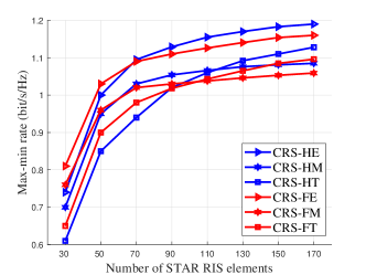
IV-B1 Comparison among STAR RIS operating protocols

From Fig. 5, we observe that the FE/HE mode consistently achieves a higher max-min rate than the FM/HM and FT/HT mode. This is because the ES protocol is more general than the MS and TS protocol, and it ensures that each STAR RIS element has a larger tunable range of the amplitude coefficient. As the number of STAR RIS elements increases, the max-min rate performance gain between FM/HM and FT/HT modes decreases. Surprisingly, when N𝑁N is larger than 110110110, the FT/HT mode achieves a higher max-min rate than the FM/HM mode. This indicates that the TS protocol outperforms the MS protocol when the STAR RIS element is large. With an increasing number of STAR RIS elements, the performance improvement gained from having all elements operating within the same transmission/reflection space is outweighed by the performance degradation caused by partial time service.

Due to the superior max-min rate performance of ES compared to MS and TS, in the following simulation results, we only illustrate the proposed STAR RIS-assisted CRS in FE and HE modes for clarity.

IV-B2 Comparison between FD and HD relaying protocols

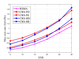
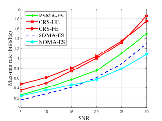
Fig. 5 illustrates the max-min rate performance versus transmit SNR. We compare our proposed CRS-FE/HE with the conventional RSMA scheme and the conventional CRS schemes with HD and FD protocols. Algorithm 3 is employed to optimize the corresponding problems of the proposed schemes. We set N=50,K=4,Nt=4formulae-sequence𝑁50formulae-sequence𝐾4subscript𝑁𝑡4N=50,K=4,N_{t}=4. The max-min rate increases with SNR for all transmission schemes. It is noteworthy that when SNR is below 252525 dB, the CRS-FE scheme achieves a higher max-min rate than the CRS-HE scheme. Conversely, when the SNR exceeds 252525 dB, the CRS-HE scheme outperforms the CRS-FE scheme. This divergence stems from the introduction of self-interference in FD relaying. As the SNR increases, the level of self-interference also rises. This indicates that the HD protocol is preferred in the high SNR regime while the FD protocol is preferred in the low and moderate SNR regimes. For consistently ensuring the optimal max-min rate performance gain, we can employ FD relaying at low and moderate SNR and HD relaying at high SNR.

From Fig. 5, it is obvious that with the assistance of STAR RIS and CRS, CRS-FE/HE achieves explicit max-min rate gain over conventional schemes. Specifically, CRS-FE demonstrates an average relative performance gain of 117.1% and 52.4% over conventional RSMA and CRS-FD, respectively. This demonstrates the significant performance enhancement achieved by integrating STAR RIS and CRS.

IV-B3 Comparison among different MA schemes

In Fig. 5, we compare various STAR RIS-assisted transmission schemes with the ES protocol when N=50𝑁50N=50, K=4𝐾4K=4, Nt=4subscript𝑁𝑡4N_{t}=4. The results show that our proposed STAR RIS-aided CRS scheme outperforms other MA schemes. It achieves an average max-min rate gain of 42.6% over the RSMA-ES scheme, 90.9% over the SDMA-ES scheme, and 77.2% over the NOMA-ES scheme. Besides, the RSMA-ES scheme outperforms NOMA-ES and SDMA-ES. By splitting the user message into common and private parts, RSMA facilitates more flexible interference management in all SNR regimes.

Refer to caption
(a) Max-min rate versus N𝑁N
Refer to caption
(b) Average CPU time versus N𝑁N
Figure 6: The performance of the two proposed algorithms.

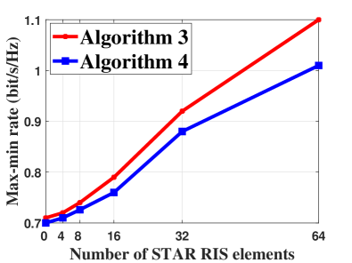
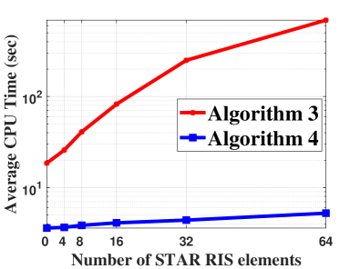
IV-B4 Comparison between the two proposed algorithms

In Fig. 6, we compare the two proposed optimization algorithms for the proposed STAR RIS-aided CRS in the ES mode. We set SNR=20SNR20\mathrm{SNR}=20 dB, K=4𝐾4K=4, Nt=4subscript𝑁𝑡4N_{t}=4. In comparison to the proposed AO algorithm, the low-complexity algorithm reduces the average CPU time by 99.2% while incurring only a 9.1% performance loss at N=64𝑁64N=64. This confirms the effectiveness of the proposed low-complexity algorithm. This efficiency is primarily due to the low-complexity algorithm eliminating the need for CVX operations to update 𝚯rsubscript𝚯𝑟\bm{\Theta}_{r} and 𝚯tsubscript𝚯𝑡\bm{\Theta}_{t}, along with the alternative optimization between two subproblems. Instead, CVX is exclusively used for joint power, common rate, and time allocation, leading to a significant reduction in optimization dimension. The results suggest that if the system can accommodate high time complexity, Algorithm 3 should be employed to achieve near-optimal max-min rate performance. Conversely, if the system is time sensitive, the low-complexity Algorithm is recommended.

V Conclusion

In this paper, we propose a novel STAR RIS-assisted CRS transmission with six different transmission modes, namely, HE, HM, HT, FE, FM, FT. With the objective of maximizing the minimum user rate, we then propose a unified SCA-based AO algorithm to optimize the BS active beamforming and the STAR RIS passive beamforming iteratively under the transmit power constraint at the BS and the law of energy conservation at the STAR RIS. Meanwhile, we propose a novel low-complexity resource allocation algorithm that designs the BS active beamforming and the STAR RIS passive beamforming in closed form. Numerical results show that our proposed STAR RIS aid-CRS system achieves superior max-min rate performance gain over the existing CRS schemes and the STAR RIS-aided MA schemes. Furthermore, we show that the FD relaying has better max-min rate performance at low and moderate SNR while the HD relaying is preferred at high SNR. The ES protocol offers superior max-min rate performance compared to the MS and TS protocols, albeit with increased hardware complexity. With a large number of STAR RIS elements, the TS protocol demonstrates a significantly higher max-min rate gain compared to the MS protocol. Our proposed AO algorithm is better suited for systems that can accommodate higher time complexity, while the low-complexity algorithm is preferable for systems that are more time sensitive.

References

  • [1] K. Zhao, Y. Mao, and Y. Shi, “STAR-RIS empowered full duplex cooperative rate splitting,” in IEEE VTC2023-Fall, 2023, pp. 1–5.
  • [2] B. Clerckx, Y. Mao, E. A. Jorswieck, J. Yuan, D. J. Love, E. Erkip, and D. Niyato, “A primer on rate-splitting multiple access: Tutorial, myths, and frequently asked questions,” IEEE J. Sel. Areas Commun., May 2023.
  • [3] Y. Mao, B. Clerckx, and V. O. K. Li, “Rate-splitting multiple access for downlink communication systems: Bridging, generalizing, and outperforming SDMA and NOMA,” EURASIP J. Wireless Commun. Netw., vol. 2018, no. 1, p. 133, May 2018.
  • [4] Y. Mao, B. Clerckx, and V. O. Li, “Rate-splitting for multi-antenna non-orthogonal unicast and multicast transmission: Spectral and energy efficiency analysis,” IEEE Trans. Commun., vol. 67, no. 12, pp. 8754–8770, Sep 2019.
  • [5] B. Clerckx, Y. Mao, R. Schober, and H. V. Poor, “Rate-splitting unifying SDMA, OMA, NOMA, and multicasting in MISO broadcast channel: A simple two-user rate analysis,” IEEE Wireless Commun. Lett., vol. 9, no. 3, pp. 349–353, Nov. 2019.
  • [6] J. Zhang, B. Clerckx, J. Ge, and Y. Mao, “Cooperative rate splitting for MISO broadcast channel with user relaying, and performance benefits over cooperative NOMA,” IEEE Signal Process. Lett., vol. 26, no. 11, pp. 1678–1682, Nov. 2019.
  • [7] Y. Mao, B. Clerckx, J. Zhang, V. O. K. Li, and M. A. Arafh, “Max-min fairness of k𝑘k-user cooperative rate-splitting in MISO broadcast channel with user relaying,” IEEE Trans. Wireless Commun., vol. 19, no. 10, pp. 6362–6376, Oct. 2020.
  • [8] S. Khisa, M. Almekhlafi, M. Elhattab, and C. Assi, “Full duplex cooperative rate splitting multiple access for a MISO broadcast channel with two users,” IEEE Commun. Lett., vol. 26, no. 8, pp. 1913–1917, May 2022.
  • [9] T. Li, H. Zhang, X. Zhou, and D. Yuan, “Full-duplex cooperative rate-splitting for multigroup multicast with SWIPT,” IEEE Trans. Wireless Commun., vol. 21, no. 6, pp. 4379–4393, Nov 2021.
  • [10] Q. Pan, J. Wu, X. Zheng, W. Yang, and J. Li, “Differential privacy and irs empowered intelligent energy harvesting for 6G internet of things,” IEEE Internet Things J., vol. 9, no. 22, pp. 22 109–22 122, Aug 2021.
  • [11] E. Basar, M. Di Renzo, J. De Rosny, M. Debbah, M.-S. Alouini, and R. Zhang, “Wireless communications through reconfigurable intelligent surfaces,” IEEE Access, vol. 7, pp. 116 753–116 773, Aug 2019.
  • [12] Z. Li, W. Yuan, B. Li, J. Wu, C. You, and F. Meng, “Reconfigurable intelligent surface aided OTFS: Transmission scheme and channel estimation,” IEEE Internet Things J., Apr 2023.
  • [13] Y. Liu, X. Mu, J. Xu, R. Schober, Y. Hao, H. V. Poor, and L. Hanzo, “STAR: Simultaneous transmission and reflection for 360° coverage by intelligent surfaces,” IEEE Wireless Commun., vol. 28, no. 6, pp. 102–109, Dec 2021.
  • [14] H. Zhang and B. Di, “Intelligent omni-surfaces: Simultaneous refraction and reflection for full-dimensional wireless communications,” IEEE Commun. Surv. Tut., Aug 2022.
  • [15] C. Wu, Y. Liu, X. Mu, X. Gu, and O. A. Dobre, “Coverage characterization of STAR-RIS networks: NOMA and OMA,” IEEE Commun. Lett., vol. 25, no. 9, pp. 3036–3040, Jun. 2021.
  • [16] Z. Zhang, J. Chen, Y. Liu, Q. Wu, B. He, and L. Yang, “On the secrecy design of STAR-RIS assisted uplink NOMA networks,” IEEE Trans. Wireless Commun., vol. 21, no. 12, pp. 11 207–11 221, Jul. 2022.
  • [17] J. Zuo, Y. Liu, Z. Ding, L. Song, and H. V. Poor, “Joint design for simultaneously transmitting and reflecting (STAR) RIS assisted NOMA systems,” IEEE Trans. Wireless Commun., vol. 22, no. 1, pp. 611–626, Aug. 2022.
  • [18] H. R. Hashempour, H. Bastami, M. Moradikia, S. A. Zekavat, H. Behroozi, and A. L. Swindlehurst, “Secure SWIPT in STAR-RIS aided downlink MISO rate-splitting multiple access networks,” arXiv preprint arXiv:2211.09081, Nov 2022.
  • [19] M. Katwe, K. Singh, B. Clerckx, and C.-P. Li, “Improved spectral efficiency in STAR-RIS aided uplink communication using rate splitting multiple access,” IEEE Trans. Wireless Commun., Jan. 2023.
  • [20] S. Dhok and P. K. Sharma, “Rate-splitting multiple access with STAR RIS over spatially-correlated channels,” IEEE Trans. Commun., vol. 70, no. 10, pp. 6410–6424, Aug. 2022.
  • [21] B. Clerckx, H. Joudeh, C. Hao, M. Dai, and B. Rassouli, “Rate splitting for MIMO wireless networks: A promising PHY-layer strategy for LTE evolution,” IEEE Commun. Mag., vol. 54, no. 5, pp. 98–105, May 2016.
  • [22] Y. Mao, O. Dizdar, B. Clerckx, R. Schober, P. Popovski, and H. V. Poor, “Rate-splitting multiple access: Fundamentals, survey, and future research trends,” IEEE Commun. Surv. Tut., Jun. 2022.
  • [23] T. Riihonen, S. Werner, and R. Wichman, “Mitigation of loopback self-interference in full-duplex MIMO relays,” IEEE Trans. Signal Process., vol. 59, no. 12, pp. 5983–5993, Dec. 2011.
  • [24] A. Sabharwal, P. Schniter, D. Guo, D. W. Bliss, S. Rangarajan, and R. Wichman, “In-band full-duplex wireless: Challenges and opportunities,” IEEE J. Sel. Areas Commun., vol. 32, no. 9, pp. 1637–1652, Sep. 2014.
  • [25] C. Zhong, H. A. Suraweera, G. Zheng, I. Krikidis, and Z. Zhang, “Wireless information and power transfer with full duplex relaying,” IEEE Trans. Commun., vol. 62, no. 10, pp. 3447–3461, Oct. 2014.
  • [26] J. Hu and N. C. Beaulieu, “Performance analysis of decode-and-forward relaying with selection combining,” IEEE Commun. Lett., vol. 11, no. 6, pp. 489–491, Jun. 2007.
  • [27] Z. Yang, M. Chen, W. Saad, W. Xu, M. Shikh-Bahaei, H. V. Poor, and S. Cui, “Energy-efficient wireless communications with distributed reconfigurable intelligent surfaces,” IEEE Trans. Wireless Communi., vol. 21, no. 1, pp. 665–679, Jul. 2021.
  • [28] T. Fang and Y. Mao, “A low-complexity beamforming design for beyond-diagonal RIS aided multi-user networks,” IEEE Commun. Lett., vol. 28, no. 1, pp. 203–207, 2024.
  • [29] C. Oestges and B. Clerckx, MIMO wireless communications: from real-world propagation to space-time code design.   Academic Press, 2010.
  • [30] X. Mu, Y. Liu, L. Guo, J. Lin, and R. Schober, “Simultaneously transmitting and reflecting (STAR) RIS aided wireless communications,” IEEE Trans. Wireless Commun., vol. 21, no. 5, pp. 3083–3098, Oct. 2021.