A continuous beam monochromator for matter waves
Abstract
Atom and, of late, molecule interferometers find application in both the crucible of fundamental research and industrial pursuits. A prevalent methodology in the construction of atom interferometers involves the utilisation of gratings fashioned from laser beams. While this approach imparts commendable precision, it is hampered by its incapacity to attain exceedingly short wavelengths and its dependence on intricate laser systems for operational efficacy. All applications require the control of matter waves, particularly the particle’s velocity. In this manuscript, we propose a continuous beam monochromator scheme reaching enormously high velocity purification with speed ratios in the order of based on atom-surface diffraction. Beyond these high purifications, the proposed scheme simplifies the application by reducing the degree of freedom to a single angle, selecting the wanted particle’s velocity.
1 Introduction
Atom interferometry is one of the advanced investigation techniques in modern physics[1, 2] covering a wide range from fundamental research, such as the transition between the classical and the quantum world due to high mass [3] or slower particles, [4, 5] via as well as magnetic and gravity sensing [6, 7], quantum metrology [8], atomic clocks [9], dark matter and gravitational wave detectors [10] also in space [11, 12] to matter-wave lithography. [13, 14] Recently, portable atom gravimeters for geophysical investigations, such as prospecting and oil survey, have become commercially available. [15]
Atom interferometers are also proposed as accelerometers for sub-sea navigation in submarines and underwater drones [16, 7]. However, reaching the envisaged accuracy requires either a velocity-sensitive measurement or an accurate velocity preselection. Velocity-sensitive measurements are challenging but realisable. [5, 17, 18]
A measure for the wave’s monochromaticity is speed ratios (ratio between velocity and velocity spread , ). To reach large speed ratios, one needs control of the particle’s trajectories[17, 19] and a low particle flux[5] to distinguish each particle. An alternative to a velocity-sensitive measurement is velocity preselection, enabling high-contrast interferences. Here, we differentiate between two principles: (a) changing the momentum of particles with the wrong velocity (momentum) or (b) removing the particles with a different momentum.
Velocity-dependent accelerating or decelerating particles within a particle beam have been realised by the Rydberg–Stark decelerator, a chain of quadrupoles creating an inhomogeneous field that couples differently to the dipoles moving with different velocities.[20, 21, 22, 21] Thus, this technique is restricted to particles with a permanent dipole moment. Another possibility is the Zeeman slower, which works analogously to the Stark effect but uses magnetic fields coupled to the spin-polarised magnetic moment.
The more straightforward solution is removing the particles from the beam with a velocity different from the target velocity, which can be realised using two choppers, which only transmit particles with a velocity matching the time window for the chopper openings. This technique has been realised in various configurations and setups, e.g., a cascade of choppers [23] or a helical gearwheel[24, 25]. However, it has the apparent disadvantage that a continuous beam will be pulsed. A further possibility, removing particles with an unwanted velocity from a beam, uses atomic mirrors, which has been demonstrated experimentally[26] as well as the slowing of atomic beams, the so-called atomic paddle [27], Stark effect decelerator [28] and Zeeman slower [29].
Here, we present a novel approach to velocity selection which enables a continuous beam with speed ratios up to several hundred by exploiting the recently proposed reflective atom interferometer [30]. The example presented here is for a helium beam scattering off hydrogen-passivated Si(111).[31] However, the proposed device can be adapted to other materials and atomic beams. The reflection direction is velocity-sensitive depending on the surface structure. Thus, by sending the reflected (diffracted) beam through a pinhole, the particles with a velocity outside a specific range will be blocked, and the beam’s speed ratio will be enhanced. The velocity-dependent beam spread is increased using three reflections instead of one (simple reflection scheme). Experimentally, this is made possible by the monolithic nature of the atom interferometer, which ensures that the reflective surfaces do not move relative to each other.
2 The monochromator
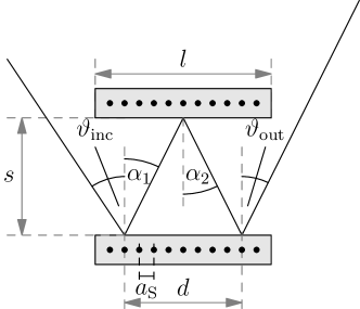
The proposed monochromator for matter waves is based on the reflective atom interferometer introduced in Ref. [30], which consists of two parallel structured plates cut into a single crystal. It requires two parallel nano-structured planar surfaces, which can be achieved by cutting a monolithic crystal, such as silicon, and chemically dipping the Si(111) crystal in an HF solution.[32] The incoming beam is diffracted three times within the device before leaving. For each diffraction, the incidence and reflection angles are related by Bragg’s law
| (1) |
with the diffraction order , the de-Broglie wavelength , the reduced Planck constant , the particle’s mass and velocity , and the lattice constant of the structured surface . Due to the structure of this equation, the three internal diffractions lead to a total diffraction order for the entire device . Figure 1 illustrates the situation. In previous work [30], we have seen a strong dependency of the diffraction orders’ positions on the incoming beam’s wavelength, which motivated the further consideration of the device to act as a monochromator. In the following, we will first consider the relation between the incidence and reflection angle with respect to velocity deviations. One of these angles should be fixed for practical applications, where we used the outgoing angle . Thus, we first analyse the optimal incidence angle concerning a strong velocity dependence. Afterwards, we derive conditions for the device’s dimensions, expressed in the length-to-separation ratio , allowing for an almost arbitrary scaling of the device. All given examples consider a helium beam in a monolithic Si(111)-H(11) device according to Ref. [30].
2.1 Optimal incidence angle
The diffraction angles in the monolithic monochromator are determined by[30]
| (2) |
To diffract most of the unwanted velocities of the incoming beam, a large variance of the diffraction angle with respect to velocity changes is required
| (3) |
Thus, the diffraction angle must be large to achieve a wide spread of the velocity distribution. The optimum would be mathematically at . However, this solution means that the outcoming beam is parallel to the slab, leaving the application scope of Eq. 1. We introduce a small angle to compensate for this effect, ensuring non-parallel beams, and the outcoming diffraction angle reads leading to an incidence angle
| (4) |
Furthermore, a small lattice constant is required .
For applicational purposes, we set the output beam to a specific value, . This means the device always works with a fixed output angle, and the velocity selection occurs by changing the input angle. Figure 2 illustrates the dependence of the incidence angles for different beam velocities of a helium beam diffracted in a monolithic hydrogen-passivised silicon monochromator with a lattice constant Å. [33] It can be seen that the lower diffraction orders cover a larger velocity range.
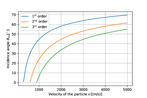
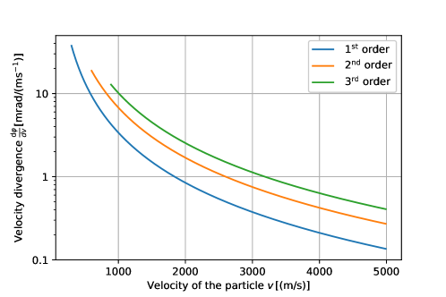
Figure 3 illustrates the corresponding velocity divergence (3). It can be seen that the higher diffraction orders are more sensitive to velocity changes than the lower ones.
2.2 Optimal dimensions of the monochromator
The monochromator is based on three diffractive reflections between two parallel plates separated by a distance . The first reflection is described by the diffraction angle
| (5) |
the second one by
| (6) |
and finally, the exiting beam
| (7) |
By inserting these equations into each other, one finds the condition for the last diffraction order
| (8) |
To determine the extension of the device, the diffractions need to occur within a certain length (spatial distance between reflection 1 and 3) smaller than the length of the device , whose ratio to separation is given by the diffraction angles
| (9) |
which is bounded by
| (10) | ||||
| (11) |
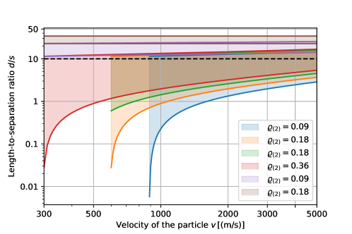
The lower bound ensures three reflections and the upper bound for the beam leaving the device. Figure 4 illustrates this condition for a monochromator made off monolithic Si(111)-H(11) for a helium beam operating on the first total diffraction order . We consider the internal diffraction orders to be from -2 to 2. Thus, 25 paths are possible, from which sixteen occur due to the criterion (11), and eight are pairwise equal, leading to twelve different paths. In Figure 4, we depicted six paths, which are labelled by the total transmission rate as the product of the diffraction populations at each diffraction point, (index labels the number of considered reflections), where we used the reflection probability for the zeroth, first and second order diffraction according to Ref. [30, 33]. It can be observed that due to the large diffraction angle for the outgoing beam (), a wide range of length-to-separation ratios can be covered. Furthermore, not all combinations of internal diffraction orders fit all particle velocities. A ratio of 10 will cover the entire considered velocity range.
2.3 Continous velocity selection - a practical example
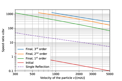
Let us consider a monolithic Si(111)-H(11) monochromator with lattice constant Å,[33] a length and a slap separation . These parameters lead to a length-to-separation ratio of 10, covering the entire velocity range from 300 to 5000 m/s for the helium beam, see Fig. 4. The lower bound is determined by the period of the slab’s structure . Another material has to be chosen to reach lower velocities. We consider a plane wave entering the device through a pinhole with a 1 mm diameter 10 cm away from the device under an optimal incidence angle according to Eq. (4) for a total reflection angle of . We have chosen the first total diffraction order as the working point, blue lines in Figs 2 and 3. In addition, we considered two further pinholes 50 cm and 1 m after the device with a diameter of 1 cm each to block the background signal, such as contributions from other diffractions. For the simulation, we considered a rectangular velocity distribution with a symmetric width of 500 m/s around the central velocity, . We calculated the propagation of this wave package using ray optics and determined the speed ratio after passing the final pinhole. The results are depicted in Fig. 5. It can be seen that the monochromator yields excellent speed ratios for small particle velocities (below ) where it reaches values around 1000. In the medium range, around 2000 m/s, it is comparable to and slightly better than current techniques. The speed ratio decreases for high particle velocities due to the worse velocity divergence in this range; see Fig. 3. The speed ratio for a single reflection with an incidence angle of , achieving a transmission over a wide velocity range into the first order, is compared. It can be seen that the triple reflection monochromator yields an enhancement by one order of magnitude.
2.4 Discussion
We introduce a novel monochromator scheme for matter waves and demonstrate the resulting large achievable speed ratios (up to 600 to 1000) over a wide velocity range (up to ). For a numerical example, we restricted ourselves to the consideration of helium beams. However, the device can be adapted to several other species. An increase in the particle’s mass would yield a left shift of all curves (Figs. 2–5) towards lower velocities. To adapt the monochromator to even smaller velocities, the lattice constant needs to increase to diffract the particles with lower velocities.
According to the incoming matter wave, its velocity spread must be restricted. It can be observed in Fig. 2 that an incoming beam with a certain incidence angle will be diffracted to the same spot for three different velocities. The transmitted velocities have an integer ratio, , where denotes the total diffraction order, meaning that is transmitted via the second diffraction order and via the third one, and so on. Thus, if the velocity spread of the incoming wave () is wide enough to cover two or three total diffraction orders (Fig. 2), the outgoing beam will have a narrow velocity distribution around each of the two or three selected velocities.
The proposed monochromator uses three reflections to separate the velocity contributions of the beam. However, a single reflection would also reduce the velocity spread and provide a large transmission. [26] By comparing these different setups, there are some advantages for the three-reflection monochromator: (i) Due to the free-propagation between the reflection points, the velocity-dependent beam spread is wider, purifying the beam more than with a single reflection. (ii) The arrangement is easy to handle when the selected velocity is changed as it keeps one angle fixed.
3 Conclusions
We present a novel continuous beam monochromator scheme based on reflection atom interferometry, providing atom beams with high speed ratios and working across a broad velocity range. Due to the monolithic configuration, the proposed device will be easy to handle because only the incidence angle has to be tuned according to the wanted mean velocity. The theoretical calculations result in low transmission rates, which can be improved, for instance, by using quantum reflection [34] or reflection at evanescent potentials [35].
Acknowledgments
J.F. gratefully acknowledges support from the European Union (H2020-MSCA-IF-2020, grant number: 101031712).
References
- [1] G. M. Tino and M. A. Kasevich, editors. Atom Interferometry, Amsterdam, Oxford, Tokio, Washington DC, 2014. IOS Press.
- [2] J. Fiedler, K. Berland, J. W. Borchert, R. W. Corkery, A. Eisfeld, D. Gelbwaser-Klimovsky, M. M. Greve, B. Holst, K. Jacobs, M. Krüger, D. F. Parsons, C. Persson, M. Presselt, T. Reisinger, S. Scheel, F. Stienkemeier, M. Tømterud, M. Walter, R. T. Weitz, and J. Zalieckas. Perspectives on weak interactions in complex materials at different length scales. Phys. Chem. Chem. Phys., 25:2671–2705, 2023.
- [3] Yaakov Y Fein, Philipp Geyer, Patrick Zwick, Filip Kiałka, Sebastian Pedalino, Marcel Mayor, Stefan Gerlich, and Markus Arndt. Quantum superposition of molecules beyond 25 kDa. Nature Physics, 15(12):1242–1245, 2019.
- [4] T Taillandier-Loize, S A Aljunid, F Correia, N Fabre, F Perales, J M Tualle, J Baudon, M Ducloy, and G Dutier. A simple velocity-tunable pulsed atomic source of slow metastable argon. Journal of Physics D: Applied Physics, 49(13):135503, mar 2016.
- [5] C. Garcion, N. Fabre, H. Bricha, F. Perales, S. Scheel, M. Ducloy, and G. Dutier. Intermediate-range casimir-polder interaction probed by high-order slow atom diffraction. Phys. Rev. Lett., 127:170402, Oct 2021.
- [6] Ben Stray, Andrew Lamb, Aisha Kaushik, Jamie Vovrosh, Anthony Rodgers, Jonathan Winch, Farzad Hayati, Daniel Boddice, Artur Stabrawa, Alexander Niggebaum, Mehdi Langlois, Yu-Hung Lien, Samuel Lellouch, Sanaz Roshanmanesh, Kevin Ridley, Geoffrey de Villiers, Gareth Brown, Trevor Cross, George Tuckwell, Asaad Faramarzi, Nicole Metje, Kai Bongs, and Michael Holynski. Quantum sensing for gravity cartography. Nature, 602(7898):590–594, 2022.
- [7] K. S. Hardman, P. J. Everitt, G. D. McDonald, P. Manju, P. B. Wigley, M. A. Sooriyabandara, C. C. N. Kuhn, J. E. Debs, J. D. Close, and N. P. Robins. Simultaneous precision gravimetry and magnetic gradiometry with a bose-einstein condensate: A high precision, quantum sensor. Physical Review Letters, 117(13):138501, Sep 2016.
- [8] Max F. Riedel, Pascal Böhi, Yun Li, Theodor W. Hänsch, Alice Sinatra, and Philipp Treutlein. Atom-chip-based generation of entanglement for quantum metrology. Nature, 464(7292):1170–1173, 2010.
- [9] Andrew D. Ludlow, Martin M. Boyd, Jun Ye, E. Peik, and P.O. Schmidt. Optical atomic clocks. Reviews of Modern Physics, 87(2):637–701, jun 2015.
- [10] Benjamin Canuel, S Abend, P Amaro-Seoane, F Badaracco, Q Beaufils, Andrea Bertoldi, Kai Bongs, Philippe Bouyer, Claus Braxmaier, W Chaibi, N Christensen, F Fitzek, G Flouris, Naceur Gaaloul, S Gaffet, C L Garrido Alzar, R Geiger, S Guellati-Khelifa, Klemens Hammerer, J Harms, J Hinderer, M Holynski, J Junca, S Katsanevas, C Klempt, C Kozanitis, Markus Krutzik, Arnaud Landragin, I Làzaro Roche, B Leykauf, Y-H Lien, S Loriani, S Merlet, M Merzougui, M Nofrarias, P Papadakos, F Pereira dos Santos, Achim Peters, D Plexousakis, M Prevedelli, E M Rasel, Y Rogister, S Rosat, Albert Roura, D O Sabulsky, V Schkolnik, D Schlippert, Christian Schubert, L Sidorenkov, J-N Siemß, C F Sopuerta, Fiodor Sorrentino, C Struckmann, Guglielmo Maria Tino, G Tsagkatakis, A Viceré, Wolf von Klitzing, L Woerner, and X Zou. Elgar – a european laboratory for gravitation and atom-interferometric research. Classical and Quantum Gravity, 37(22):225017, oct 2020.
- [11] Yousef Abou El-Neaj, Cristiano Alpigiani, Sana Amairi-Pyka, Henrique Araújo, Antun Balaž, Angelo Bassi, Lars Bathe-Peters, Baptiste Battelier, Aleksandar Belić, Elliot Bentine, José Bernabeu, Andrea Bertoldi, Robert Bingham, Diego Blas, Vasiliki Bolpasi, Kai Bongs, Sougato Bose, Philippe Bouyer, Themis Bowcock, William Bowden, Oliver Buchmueller, Clare Burrage, Xavier Calmet, Benjamin Canuel, Laurentiu-Ioan Caramete, Andrew Carroll, Giancarlo Cella, Vassilis Charmandaris, Swapan Chattopadhyay, Xuzong Chen, Maria Luisa Chiofalo, Jonathon Coleman, Joseph Cotter, Yanou Cui, Andrei Derevianko, Albert De Roeck, Goran S. Djordjevic, Peter Dornan, Michael Doser, Ioannis Drougkakis, Jacob Dunningham, Ioana Dutan, Sajan Easo, Gedminas Elertas, John Ellis, Mai El Sawy, Farida Fassi, Daniel Felea, Chen-Hao Feng, Robert Flack, Chris Foot, Ivette Fuentes, Naceur Gaaloul, Alexandre Gauguet, Remi Geiger, Valerie Gibson, Gian Giudice, Jon Goldwin, Oleg Grachov, Peter W. Graham, Dario Grasso, Maurits van der Grinten, Mustafa Gündogan, Martin G. Haehnelt, Tiffany Harte, Aurélien Hees, Richard Hobson, Jason Hogan, Bodil Holst, Michael Holynski, Mark Kasevich, Bradley J. Kavanagh, Wolf von Klitzing, Tim Kovachy, Benjamin Krikler, Markus Krutzik, Marek Lewicki, Yu-Hung Lien, Miaoyuan Liu, Giuseppe Gaetano Luciano, Alain Magnon, Mohammed Attia Mahmoud, Sarah Malik, Christopher McCabe, Jeremiah Mitchell, Julia Pahl, Debapriya Pal, Saurabh Pandey, D. G. Papazoglou, Mauro Paternostro, Bjoern Penning, Achim Peters, Marco Prevedelli, Vishnupriya Puthiya-Veettil, John Quenby, Ernst Rasel, Sean Ravenhall, Jack Ringwood, Albert Roura, D O Sabulsky, Muhammed Sameed, Ben Sauer, Stefan Alaric Schäffer, Stephan Schiller, Vladimir Schkolnik, Dennis Schlippert, Christian Schubert, Haifa Rejeb Sfar, Armin Shayeghi, Ian Shipsey, Carla Signorini, Yeshpal Singh, Marcelle Soares-Santos, Fiodor Sorrentino, Timothy Sumner, Konstantinos Tassis, Silvia Tentindo, Guglielmo Maria Tino, Jonathan N. Tinsley, James Unwin, Tristan Valenzuela, Georgios Vasilakis, Ville Vaskonen, Christian Vogt, Alex Webber-Date, André Wenzlawski, Patrick Windpassinger, Marian Woltmann, Efe Yazgan, Ming-Sheng Zhan, Xinhao Zou, and Jure Zupan. Aedge - atomic experiment for dark matter and gravity exploration in space. EPJ Quantum Technology, 7(1):6, 2020.
- [12] G. M. Tino and et al. Precision gravity tests with atom interferometry in space. Nuc. Phys. B, 243-244:203, 2013.
- [13] Torstein Nesse, Ingve Simonsen, and Bodil Holst. Nanometer-resolution mask lithography with matter waves: Near-field binary holography. Phys. Rev. Applied, 11:024009, Feb 2019.
- [14] Johannes Fiedler and Bodil Holst. An atom passing through a hole in a dielectric membrane: impact of dispersion forces on mask-based matter-wave lithography. Journal of Physics B: Atomic, Molecular and Optical Physics, 55(2):025401, feb 2022.
- [15] V. Menoret, P. Vermeulen, N. Le Mogine, S. Bonvalot, P. Bouyer, A. Landragin, and B. Desruelle. Gravity measurements below with a transportable absolute quantum gravimeter. Scientific Reports, 8:12300, 2018.
- [16] Josué González-García, Alfonso Gómez-Espinosa, Enrique Cuan-Urquizo, Luis Govinda García-Valdovinos, Tomás Salgado-Jiménez, and Jesús Arturo Escobedo Cabello. Autonomous underwater vehicles: Localization, navigation, and communication for collaborative missions. Applied Sciences, 10(4), 2020.
- [17] Thomas Juffmann, Adriana Milic, Michael Müllneritsch, Peter Asenbaum, Alexander Tsukernik, Jens Tüxen, Marcel Mayor, Ori Cheshnovsky, and Markus Arndt. Real-time single-molecule imaging of quantum interference. Nature Nanotechnology, 7(5):297–300, 2012.
- [18] Christian Brand, Michele Sclafani, Christian Knobloch, Yigal Lilach, Thomas Juffmann, Jani Kotakoski, Clemens Mangler, Andreas Winter, Andrey Turchanin, Jannik Meyer, Ori Cheshnovsky, and Markus Arndt. An atomically thin matter-wave beamsplitter. Nature Nanotechnology, 10(10):845–848, 2015.
- [19] Markus Arndt, Olaf Nairz, Julian Vos-Andreae, Claudia Keller, Gerbrand van der Zouw, and Anton Zeilinger. Wave–particle duality of C60 molecules. Nature, 401(6754):680–682, oct 1999.
- [20] Stephen D Hogan. Rydberg-Stark deceleration of atoms and molecules. EPJ Techniques and Instrumentation, 3(1):2, 2016.
- [21] Sebastiaan Y.T. van de Meerakker, Nicolas Vanhaecke, and Gerard Meijer. STARK DECELERATION AND TRAPPING OF OH RADICALS. Annual Review of Physical Chemistry, 57(1):159–190, may 2006.
- [22] S. K. Tokunaga, J. M. Dyne, E. A. Hinds, and M. R. Tarbutt. Stark deceleration of lithium hydride molecules. New Journal of Physics, 11(5):055038, may 2009.
- [23] S. D. Eder, A. Salvador Palau, T. Kaltenbacher, G. Bracco, and B. Holst. Velocity distributions in microskimmer supersonic expansion helium beams: High precision measurements and modeling. Review of Scientific Instruments, 89(11):113301, 11 2018.
- [24] Thomas Juffmann, Stefan Truppe, Philipp Geyer, András G. Major, Sarayut Deachapunya, Hendrik Ulbricht, and Markus Arndt. Wave and Particle in Molecular Interference Lithography. Physical Review Letters, 103(26):263601, dec 2009.
- [25] Carola Szewc, James D. Collier, and Hendrik Ulbricht. Note: A helical velocity selector for continuous molecular beams. Review of Scientific Instruments, 81(10):106107, 10 2010.
- [26] Bodil Holst and William Allison. An atom-focusing mirror. Nature, 390(6657):244, 1997.
- [27] E. Narevicius, A. Libson, M. F. Riedel, C. G. Parthey, I. Chavez, U. Even, and M. G. Raizen. Coherent slowing of a supersonic beam with an atomic paddle. Phys. Rev. Lett., 98:103201, Mar 2007.
- [28] C. Sommer, M. Motsch, S. Chervenkov, L. D. van Buuren, M. Zeppenfeld, P. W. H. Pinkse, and G. Rempe. Velocity-selected molecular pulses produced by an electric guide. Phys. Rev. A, 82:013410, Jul 2010.
- [29] William D. Phillips and Harold Metcalf. Laser deceleration of an atomic beam. Phys. Rev. Lett., 48:596–599, Mar 1982.
- [30] Johannes Fiedler, Kim Lefmann, Wolf von Klitzing, and Bodil Holst. Monolithic atom interferometry. Phys. Rev. A, 108:023306, Aug 2023.
- [31] J. R. Buckland and W. Allison. Determination of the helium/Si(111)–(1×1)H potential. The Journal of Chemical Physics, 112(2):970–978, 2000.
- [32] D.A. MacLaren, N.J. Curson, P. Atkinson, and W. Allison. An AFM study of the processing of hydrogen passivated silicon(111) of a low miscut angle. Surface Science, 490(3):285–295, 2001.
- [33] D. Barredo, F. Calleja, A.E. Weeks, P. Nieto, J.J. Hinarejos, G. Laurent, A.L. Vazquez de Parga, D.A. MacLaren, D. Farías, W. Allison, and R. Miranda. Si(111)–H(1×1): A mirror for atoms characterized by AFM, STM, He and H2 diffraction. Surface Science, 601(1):24–29, 2007.
- [34] Lee Yeong Kim, Sanghwan Park, Chang Young Lee, Wieland Schöllkopf, and Bum Suk Zhao. Enhanced elastic scattering of he2 and he3 from solids by multiple-edge diffraction. Phys. Chem. Chem. Phys., 24:21593–21600, 2022.
- [35] Helmar Bender, Christian Stehle, Claus Zimmermann, Sebastian Slama, Johannes Fiedler, Stefan Scheel, Stefan Yoshi Buhmann, and Valery N. Marachevsky. Probing atom-surface interactions by diffraction of bose-einstein condensates. Phys. Rev. X, 4:011029, Feb 2014.