An asymmetric four-bend S-chicane compressor immune to coherent synchrotron radiation effects
Abstract
The most significant advances in x-ray free electron lasers (FELs) have been driven by the development of ingenious bunch compressors and high-brightness sources in the last several decades. Coherent synchrotron radiation (CSR) is considered a disruptive effect that hinders the reach of design targets, and its control is of essential importance for bunch compression to avoid beam phase-space quality degradation, especially transverse emittance dilution. Herein, we demonstrate a design to cancel the CSR-driven emittance excitation by arranging four adjacent bends into an asymmetric S-chicane without any use of additional components. The CSR-induced emittance growth of the proposed chicane is found to be drastically reduced by nearly one order of magnitude compared with the nominal symmetric C-chicane by particle tracking simulation. This breakthrough opens the door for the bunch compressors to meet the ever-increasing demands of future accelerator applications, especially important in the field of FELs.
The advent of x-ray free electron lasers (FELs) has been considered as a revolutionary advancement in accelerator-based light sources over the last decade because of the unprecedented high peak power, short wavelength, and high-brightness radiation [1, 2, 3, 4]. For short wavelength FELs, a very bright electron beam is essentially required,i.e. low emittance of the same order of diffraction limited emittance of photons, as well as a sufficiently low energy spread and high peak current (e.g., kiloampere level) [5]. Note that an kA peak current is unlikely generated at the electron source with energy typically below 10 MeV without beam quality degradation because of strong space charge effects. Instead, bunch compressors were proposed and widely adopted to compress the bunch at the downstream main linac with moderate or high beam energy [1, 2, 6, 7, 8]. The mechanism of bunch compression is converting energy-time correlation into density modulation, in analogy with the chirped pulse amplification (CPA) technique in laser physics [9], that was awarded the Nobel Prize in Physics in 2018 [10]. For bunch compression in FELs, an electron bunch is first imposed an energy chirp (correlation between an electron’s energy and its longitudinal position), and then pass a dispersive element that converts particle energy deviation into a path-length difference, leading to compression in longitudinal dimension [5]. The simplest, and therefore most common type of bunch compressor is the nominal symmetric C-chicane, which consists of only four bends. Besides FELs, such chicane compressors also play important roles in linacs [1], colliders [7], beam-driven plasma-wakefield accelerators [11], and energy recovery linacs [12].
Electron beams with high peak current are required to drive FELs. In this case, horizontal emittance growth and energy spread increase often occur as a consequence of coherent synchrotron radiation (CSR), which has been identified as a potentially detrimental effect associated with the design of bunch compressor chicanes required for FELs [13, 15, 14]. Typically, CSR is emitted for wavelengths longer than the length of the electron bunch and becomes more evident at shorter bunch length, and is therefore amplified in the later stages of the compression process. In the past decades, worldwide theoretical and experimental studies have been invested to understand this nontrivial effect, based on which mitigation methods on the CSR effects, including the CSR-induced microbunching instabilities (MBI) [16, 17, 18, 19, 20, 21, 23, 22, 24] and transverse emittance growth [25, 27, 26, 29, 28, 30, 31] have been proposed. For example, the CSR effects can be reduced or minimized through notch collimation [25], longitudinal pulse shaping [27, 26], transverse to longitudinal emittance exchange techniques [29, 28]. In this paper we suppress the CSR-driven emittance excitation via optics optimization, where the mitigation method is embodied in the optics design and it does not require any additional equipment in the transfer line.
Optical balance method [32, 33] was proposed with the aim to cancel the CSR kick (describing the CSR-induced coordinate deviations) for the uncompressed beam and hence emittance growth with a phase advance between two achromats which, however, turns out not so effective. This is because an ideal cancellation occurs only when the CSR effects are identical in both achromats, while the CSR effects are accumulated when successively passing the bends, and the case is even worse in bunch compressors where stronger CSR fields are generated with a shorter bunch in the last few bends. Then the work reported in Ref. [34] turns to pursuing minimization rather than cancellation of the CSR kick in a single achromat, e.g., by matching a beam envelope to the CSR-induced dispersion at the exit of a single achromat. Although the method itself does not result in a zero CSR kick, it was found to be effective in mitigating CSR-induced emittance growth and is therefore widely used in practical compressor designs. Later, it was shown that the CSR kick could be canceled in a single achromat using so-called 2D point-kick analysis of the CSR, which can be applied to multibend achromats [35]. Actually, this method has inspired design studies of CSR-immune achromatic transfer lines with constant bunch length [37, 36], and very recently that of CSR-immune double-bend achromat (DBA) compressors [38]. In the latter case, to reach a zero CSR kick it requires both a shorter bending path or a weaker bending field for the second bend and an appropriate set of three-quadrupole configurations to reach a cancellation of the CSR kick with a phase space rotation between the two bends. This treatment permits us to envisage possible designs of a CSR-immune chicane.
However, there has been no theoretical analysis of the CSR kick and the possibility of self-cancelation in a single four-bend chicane compressor due to the complex CSR accumulation and the significant bunch length variation after passing through each bend. Note that a chicane compressor has more bends, while without focusing elements between bends, which makes the theoretical analysis of the CSR effects to a large degree different from that of a DBA compressor. To this end, in this Letter we develop theoretical analysis of the CSR effects in a general four-bend chicane, and based on the analysis we propose a novel asymmetric chicane self-suppressing the CSR net kick.
A symmetric C-chicane consists of four bends separated by three drifts, see Fig. 1(a). We break the geometrical symmetry of such C-chicane and arbitrarily specify the bending angles and drift lengths , while ensuring that the horizontal trajectory of the beam are coaxial before and after passing through the chicane (see Fig. 1(b)) called the beam collinear condition. Such a treatment enables us to exploit the abundant degrees of freedom of asymmetric chicane to obtain the generic CSR cancelation conditions.
For such a chicane with only several bends, it is easy to find that the achromatic condition and the beam collinear condition have identical requirements, i.e.,
| (1) | ||||
where we introduce some dimensionless quantities, relative bending angles , and relative drift lengths . For the length of bending magnets much shorter than the drift length, hereafter we can simplify Eq. (1) by neglecting the term. With such simplification, the total length and (the linear term of the chicane time-energy dependence), have the form of
| (2) |
Here the two important parameters, and , are related to the compression factor and the energy chirp as when considering the linear bunch compression.
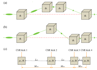
Then we perform the 2D point-kick analysis of the four-bend chicane. The idea is illustrated in Fig. 1(c). In a bend, the accumulated CSR effect along the curved trajectory can be greatly simplified to a point-kick that occurs at the center of the bend [32]. The net CSR kick for a four-bend achromat can be summed by calculating the coordinates after the four CSR kicks and the betatron transportation through the beam line between the centers of the bends.
The particle experiences a CSR kick at the center of a bend, with a horizontal coordinate deviation and an energy deviation , which are of the form [35]
| (3) | ||||
where and is the beam bending radius. Here is the particle’s initial energy deviation. The strength of the CSR effect is usually quantified by a parameter when considering a Gaussian bunch as [35]
| (4) |
with the electron population, the classical electron radius, the relativistic Lorentz factor, and the rms electron bunch length.
Considering the bunch length variation during compression, we allow different bunch lengths in different bends but in each bend the bunch length remains constant. This treatment permits us to apply this point-kick analysis to multibend achromat with bunch length variation. Note that such an assumption has recently been proven appropriate in the application of DBA-based bunch compressor [38], and does not affect our understanding of the main physical process involved in bunch length compression. For our studied four-bend chicane using point-kick analysis, the bunch lengths at the centers of bends are adopted. Exceptionally, for the sake of simplicity, we assume that the bunch lengths in the first and fourth bends are equal to the bunch lengths at the entrance and exit of the chicane, denoted by and , respectively.
Consider a zero initial energy deviation of and a zero initial coordinates of at the entrance of the chicane. To cancel the CSR net kick, we let . In this way the emittance growth can be minimized and the CSR cancelation conditions (see Ref. [39] for further derivations) can be derived as
| (5) | ||||
here Eq. (1) and the second member of Eq. (5) can be combined to yield the last member of Eq. (5), and it is easily verified that the parameters , , and are all positive. The relationships between are functions of and compression factor . Equation (5) provides requirements for both bending angle and drift length to cancel the CSR net kick. With kept constant, the three drift lengths are required in certain proportions, which can be achieved by tuning the bends in the middle of the chicane (i.e., the second and third bends) in conjunction with adjustments to the bending angles. Such requirements differ from those of DBA or triple-bend achromat compressors, where the angle and transfer matrix between bends can be clearly decoupled.
Note that Eq. (5) provides valuable information. First, the widely used symmetric C-chicane (plotted in Fig. 1(a)) seems not to support full cancelation of the the CSR kick. This can be easily confirmed by substituting the chicane information in Eq. (5). Note that the second member of Eq. (5) results in a negative such that a “negative drift” is needed. In principle a “negative drift” can be realized by replacing the drift by a focusing section with several quadrupoles [40]. Nevertheless, it increases the overall system complexity. Second, an asymmetric chicane with S geometry (sketched in Fig. 1(b)) appears to be an optimal choice for achieving both the simplicity of structure and zero CSR net kick simultaneously. To achieve this goal, the values of and in Eq. (5) should be positive. If we classify the geometric shape of the chicane according to the positive or negative of or , there are four possible cases. Analysis shows that only the case with negative and positive allows for positive and (see Ref. [39] for further details), which further requires,
| (6) |
The above angle conditions reveal that the CSR-immune chicane has an S geometry. Note that, the numerical simulations in Refs. [31, 30, 41] were aimed at suppressing the CSR-induced emittance growth and analogous S-type chicane layouts with more bends (e.g., five or six bends) were proposed. Here we appear that a minimum of four bends are sufficient to form a CSR-immune chicane.
Let us consider a more specific and practical design of the S chicane. First, one can adjust and to achieve the specific values of and (as described in Eq. (2)), thus ensuring a flexible layout for different design scenarios. And the specific chicane layout can be realized by adjusting the ratios of other bending angles and other drift lengths to and , respectively. Second, the presence of the achromatic condition in Eq. (1) imposes the requirements of two relative quantities, here we consider and . Consequently, three ratios, , , and , are free knobs. When one parameter is fixed, the other two parameters can be obtained as a function of compression factor by solving the CSR kick cancellation conditions in Eq. (5). Note that it is difficult to obtain explicit expressions of the CSR cancellation conditions as for DBA compressors [38], but it is feasible to solve Eq. (5) numerically.
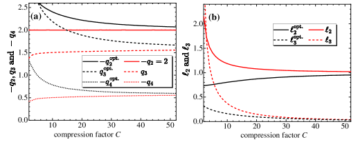
First, to mimic the previously proposed symmetric S chicane, we set . Variations of the values of , , ,and with compression factor from Eqs. (1) and (5) are plotted as the red lines in Fig. 2. Compared with the symmetric S-chicane, we see that the strengths in the last two bends are significantly reduced, as shown in Fig. 2(a). This characteristic is similar to the asymmetric C-chicane and asymmetric DBA compressors introduced in Refs. [38, 40]. In addition, the trends of , vs. compression factor are interesting. Initially, for small compression factor , and exhibit a sharp increase, followed by a considerably slower growth for a wide range of compression factor . Figure 2(b) shows the drift length ratios as a function of compression factor . In the case of strong compression, the values of and are almost restricted to the range of and , respectively. A too small indicates a short distance between the last two bends, which limits the applicability of such scenario with a high compression factor, i.e., a lower limit of 0.1 for leads to the practical maximum .
From the above, we can also see that, , is the strongest bending angle for this asymmetric S-chicane, for the case of special interest, i.e. , which means that the second bend requires a larger magnetic field . Limited by the given maximum magnet strength (reflected by ), analysis shows that an optimal (denoted as ) can be found numerically to realize a minimum in the case of constant and compression factor . Note that varies with the compression factor and is independent of the set , and . Therefore, other parameters vary with accordingly (see the black lines in Fig. 2). We also observed that, in comparison to the scenario of , the values of are larger, and the values of and are completely opposite.
To investigate the efficiency of CSR suppression, we compare the analysis predictions with the results from ELEGANT simulations [43, 42]. Here the performance of suppressing the CSR-induced emittance growth is performed for three types of chicanes: asymmetric S-chicane, symmetric C- and S-chicane. For illustration, these chicanes have been set with the same , , and the same compression factor of . Tables 1 and 2 list the typical parameters of chicane and beam for FELs. Then the correlated energy chirp is .
| Chicane parameters | Symbol | asymmetric | symmetric | symmetric |
| S-chicane | S-chicane | C-chicane | ||
| Total length (m) | 20 | |||
| First-order momen- | 47.5 | |||
| tum compaction (mm) | ||||
| Length of dipoles (m) | 1.0 | |||
| Angle of 1st dipole (∘) | 2.56 | 3.0 | 3.0 | |
| Angle of 2nd dipole (∘) | 6.16 | 6.0 | 3.0 | |
| Angle of 3rd dipole (∘) | 5.59 | 6.0 | 3.0 | |
| Angle of 4th dipole (∘) | 1.99 | 3.0 | 3.0 | |
| Length of 1st drift (m) | 8.39 | 3.75 | 8.0 | |
| Length of 2nd drift (m) | 6.73 | 8.50 | 0 | |
| Length of 3rd drift (m) | 0.88 | 3.75 | 8.0 | |
| Beam Parameters | Symbol | Value | Unit | |
|---|---|---|---|---|
| Bunch charge | 300 | pC | ||
| Initial rms bunch length | 100 | m | ||
| Beam energy | 3 | GeV | ||
| Norm. transv. emittance | 0.9 | m.rad | ||
| Rel. rms energy spread | 0.01 | % |
Table 3 lists the results of CSR-induced emittance growth at the end of three chicanes. Here the initial Twiss parameters are scanned to minimum possible emittance growth in each case (by matching the beam envelope to the CSR-induced dispersion, as highlighted in Ref. [34]). The emittance growth is over eight times smaller than that of the symmetric C- and S-chicanes, indicating a significant improvement in emittance suppression. For the proposed S-chicane, the chicane parameter scans are performed to minimize the emittance growth in the vicinity of () as predicted by point-kick analysis. The results of the parameter scan show a smaller emittance growth of 2.01% and a corresponding value of , which shifts the theoretical prediction slightly with the minimum changing only modestly. This shift is mainly due to the errors caused by the constant-bunch approximation and the ignored bend lengths. Although parameter scans and particle tracking are accurate and usually results in a promising design in the presence of CSR effects, as already described in Refs. [31, 30], this approach works only in a case-by-case sense. Here we show a demonstration rather than focusing on a practical optimal design.
The steady-state CSR-induced emittance growth is conducted above. Additionally, we simulate transport through a chicane by invoking a more accurate CSR model, henceforth denoted by all-CSR, which including the transient CSR, the drift CSR, the ISR, and the classical, single-particle synchrotron radiation). We observe that the shift also shows a slight levelling, proving the feasibility of our chicane design. Table 3 shows that the emittance growth in the proposed chicane is nearly one-tenth that of the symmetric C- and S-chicanes,regardless of whether the steady-state CSR or the all-CSR is considered. It is concluded that, despite the fact that the model prediction is derived under assumptions and only includes linear steady-state CSR, the essence of CSR cancelation is grasped in this study.
We also assess the potential MBI [18, 21] associated with the lattice and the beam parameters. Simulation results for the asymmetric S-chicane, based on the parameters presented in Tables 1 and 2, reveal a maximum gain of less than 1, exhibiting a well-controlled MBI. Indeed, apart from the CSR and its induced MBI, there are several practical effects that were not considered in this Letter, including the space charge effects, the linac geometric wake field, and many others, that may limit the performance of our design. These and other effects should be taken into account in the optimization of the practical accelerators design, and can be compensated for by parameter adjustments or global stochastic optimization methods [44].
| asymmetric | symmetric | symmetric | |
| S-chicane | S-chicane | C-chicane | |
| steady-state CSR | |||
| (m.rad) | 0.92 | 1.10 | 1.11 |
| 2.69% | 22.74% | 23.27% | |
| all-CSR | |||
| (m.rad) | 1.00 | 1.41 | 1.70 |
| 11.31% | 56.76% | 89.17% | |
In conclusion, we have demonstrated that it is feasible to cancel the CSR-induced emittance growth in a four-bend chicane based on theoretical modelling of the CSR kick. The proposed CSR-immune chicane compressor differs from traditional designs and features an asymmetric S geometry. As the intrinsic property of canceling the CSR kick, the proposed chicane reduces the emittance growth due to CSR by almost an order of magnitude from particle tracking simulations when compared to the symmetric C-chicane with the same compression target. Inspired by the fact that the theoretical results are independent of the bunch parameters and chicane design targets ( and ), we can apply such S-chicane to a more ambitious scenario with shorter bunch length and larger than those in existing C-chicane compressors. Such a design opens the door to higher peak current bunch compressors and is particularly attractive for future FELs with promising performance, and other types of accelerators, e.g., linacs, colliders, plasma-based accelerators, and energy-recovery linacs.
This work was supported by the National Natural Science Foundation of China (No. 12275284 and No. 12275094), and the Fundamental Research Funds for the Central Universities (HUST) under Project No. 2021GCRC006. We thank Cai Meng and Wei Li of IHEP for useful discussions.
References
- [1] J. Arthur, P. Anfinrud, and P. Audebert, LCLS conceptual design report, SLAC Technical Report No. SLAC-R-593, 2002.
- [2] T. Tanaka and T. Shintake, Spring-8 compact SASE source conceptual design report, Technical Report, 2005.
- [3] P. Emma, R. Akre, J. Arthur, et al. Nature Photon. 4, 641-647 (2010).
- [4] W. Ackermann, G. Asova, V. Ayvazyan, et al. Nature Photon. 1, 336-342 (2007).
- [5] Chao, Alexander Wu, et al., Handbook of accelerator physics and engineering. World scientific, 2023.
- [6] R. Ganter, Swiss FEL-conceptual design report, Paul Scherrer Institute (PSI) Technical Report No. PSI–10-04, 2010.
- [7] International Linear Collider, Technical Design Report, 2013, http://www.linearcollider.org/ILC/Publications/ Technical‑Design‑Report.
- [8] P. Emma, SLAC-PUB-10013 (1995).
- [9] D. Strickland and G. Mourou, Opt. Commun. 55, 447-449 (1985).
- [10] D. Strickland and G. Mourou, (2018), Nobel Prize in Physics. [for their method of generating high-intensity, ultra-short optical pulses]. Nobel Prize. Available from https://www.nobelprize.org/prizes/physics/2018/strickland/facts/.
- [11] E. Esarey, C. B. Schroeder and W. P. Leemans, Rev. Mod. Phys. 81, 1229-1285 (2009).
- [12] G. Hoffstaetter, S. Gruner, and M. Tigner (eds.). The Cornell Energy Recovery Linac: Project Definition Design Report. Technical report (2013).
- [13] E. L. Saldin, E. A. Schneidmiller and M. V. Yurkov, Nucl. Instrum. Meth. A 398, 373-394 (1997).
- [14] H. H. Braun, R. Corsini, L. Groening, et al., Phys. Rev. ST Accel. Beams 3, 124402 (2000).
- [15] S. Heifets, G. Stupakov and S. Krinsky, Phys. Rev. ST Accel. Beams 5, 064401 (2002).
- [16] Z. Huang and K. Kim, Phys. Rev. ST Accel. Beams 5, 074401 (2002).
- [17] Z. Huang, M. Borland, P. Emma, et al., Phys. Rev. ST Accel. Beams 7, 074401 (2004).
- [18] C. Y. Tsai, W. Qin, K. Fan, X. Wang, J. Wu and G. Zhou, Phys. Rev. Accel. Beams 23, 124401 (2020).
- [19] C. Y. Tsai, Y. S. Derbenev, D. Douglas, R. Li and C. Tennant, Phys. Rev. Accel. Beams 20, 054401 (2017).
- [20] E. Roussel, E. Ferrari, E. Allaria, et al., Phys. Rev. Lett. 115, 214801 (2015).
- [21] C. Y. Tsai, S. Di Mitri, D. Douglas, R. Li and C. Tennant, Phys. Rev. Accel. Beams 20, 024401 (2017).
- [22] M. Venturini, Phys. Rev. ST Accel. Beams 10, 104401 (2007).
- [23] M. Venturini, R. Warnock and A. Zholents, Phys. Rev. ST Accel. Beams 10, 054403 (2007).
- [24] C. Y. Tsai, Nucl. Instrum. Methods Phys. Res., Sect. A, (2019).
- [25] P. Muggli, V. Yakimenko, M. Babzien, E. Kallos and K. P. Kusche, Phys. Rev. Lett. 101, 054801 (2008).
- [26] C. Mitchell, J. Qiang and P. Emma, Phys. Rev. ST Accel. Beams 16, 060703 (2013).
- [27] G. Penco, M. Danailov, A. Demidovich, et al., Phys. Rev. Lett. 112, 044801 (2014).
- [28] D. Xiang and A. Chao, Phys. Rev. ST Accel. Beams 14, 114001 (2011).
- [29] M. Cornacchia and P. Emma, Phys. Rev. ST Accel. Beams 5, 084001 (2002).
- [30] D. Z. Khan and T. O. Raubenheimer, Phys. Rev. Accel. Beams 25, 090701 (2022).
- [31] F. Stulle, A. Adelmann and M. Pedrozzi, Phys. Rev. ST Accel. Beams 10, 031001 (2007).
- [32] D. Douglas, Thomas Jefferson National Accelerator Facility Report, Technical Report No. JLAB-TN-98-012, 1998.
- [33] S. Di Mitri, M. Cornacchia and S. Spampinati, Phys. Rev. Lett. 110, 014801 (2013).
- [34] R Hajima, Nucl. Instrum. Methods Phys. Res., Sect. A, 528, 335-339, (2004).
- [35] Y. Jiao, X. Cui, X. Huang and G. Xu, Phys. Rev. ST Accel. Beams 17, 060701 (2014).
- [36] S. Y. Kim, M. Chung, S. Doebert and E. S. Yoon, Phys. Rev. Accel. Beams 24, 021301 (2021).
- [37] C. Zhang, Y. Jiao and C. Y. Tsai, Phys. Rev. Accel. Beams 24, 060701 (2021).
- [38] C. Zhang, Y. Jiao, W. Liu and C. Y. Tsai, Phys. Rev. Accel. Beams 26, 050701 (2023).
- [39] See Supplemental Material at http://arxiv github of this Letter for the detailed derivation of the CSR cancelation conditions (2024); of this Letter for the detailed evidentiary material of the S geometry of CSR-immune chicane (2024).
- [40] F. Zeng, Y. Jiao, W. Liu and C. Y. Tsai, arXiv:2311.14896v1.
- [41] B. Beutner, doi:10.3204/DESY-THESIS-2007-040.
- [42] M. Borland, Phys. Rev. ST Accel. Beams 4, 070701 (2001).
- [43] M. Borland, Argonne National Lab., IL, Technical Report No. LS-287, (2000).
- [44] Törn, A., Ali, M. and Viitanen, S. Journal of Global Optimization 14, 437–447 (1999).