Secure Information Embedding and Extraction in Forensic 3D Fingerprinting
Abstract
The prevalence of 3D printing poses a significant risk to public safety, as any individual with internet access and a commodity printer is able to produce untraceable firearms, keys, counterfeit products, etc. To aid government authorities in combating these new security threats, several approaches have been taken to tag 3D-prints with identifying information. Known as fingerprints, this information is written into the object using various bit embedding techniques; examples include varying the height of the molten thermoplastic layers, and depositing metallic powder with different magnetic properties. Yet, the practicality of theses techniques in real-world forensic settings is hindered by the adversarial nature of this problem. That is, the 3D-printing process is out of reach of any law enforcement agencies; it is the adversary who controls all aspects of printing and possesses the printed object. To combat these threats, law enforcement agencies can regulate the manufacturing of 3D printers, on which they may enforce a fingerprinting scheme, and collect adversarially tampered remains (e.g., fragments of a broken 3D-printed firearm) during forensic investigation.
Therefore, it is important to devise fingerprinting techniques so that the fingerprint could be extracted even if printing is carried out by the adversary. To this end, we present SIDE (Secure Information Embedding and Extraction), a fingerprinting framework that tackles the adversarial nature of forensic fingerprinting in 3D prints by offering both secure information embedding and secure information extraction. First, with the help of ARM TrustZone, SIDE protects the integrity of the information embedding process such that the 3D-print is guaranteed to be tagged with the correct fingerprint. Second, by devising coding-theoretic techniques, SIDE is break-resilient, i.e., it allows correct fingerprint extraction even if the adversary breaks the 3D-print to at most a certain number of parts.
1 Introduction
3D printing brings about a revolution in consumption and distribution of goods. However, the prevalence of this technology exposes the public to various security threats. Any individual with internet access is able to produce untraceable firearms and counterfeits of IP-protected products (Figure. 1) [1, 2, 3, 4]. To aid authorities and law enforcement agencies in combating these threats, fingerprinting 3D printed objects is one potential solution. In a fingerprinting scheme, a 3D-printer embeds uniquely traceable data into the printed object (e.g., timestamp, geoposition, printer ID, etc.), that can later be extracted to trace the perpetrator, e.g., if the object was confiscated or left at a crime scene.


Various techniques for embedding bits in 3D printed objects have been proposed in the literature. For instance, embedding tags on the surface of the object by altering layer height [5], inserting cavities inside the object [6], altering the surface of the object by varying printing speed [7], embedding RFID-tags [8, 9, 10] or QR codes [11, 12], inserting acoustic barcodes using surface bumps [13], etc. For a broad introduction to the topic see [14, 15].
An orthogonal line of work in the forensic 3D-printing literature proposes to identify printers from 3D-prints using machine-learning methods, based on manufacturing imperfections of printer components reflected on the print results [16]. However, whether the proposed method provides enough resolution for a large number of 3D printers remains unknown. Moreover, [16] focuses on identifying the 3D printer from the printed object, and does not provide a method for embedding arbitrary bits. These bits, which may represent geoposition or timestamp, are unknown at the time of recording the printer’s imperfections, and are crucial for forensic applications.
The practicality of any such bit embedding technique, however, is hindered by a fundamental obstacle, i.e., the adversary controls the printing. Specifically, the adversary has full control over the entire printing process, and may manipulate the prints after committing a crime. For example, the adversary may bypass the information embedding software installed on the printer control board and print a fingerprint-free firearm. The firearm may also be broken after committing the crime, making the embedded information unrecoverable.
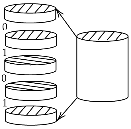
In contrast, law enforcement agencies are restricted to merely regulate the manufacturing and distribution of commercial 3D printers. Once the printer is handed over to the (potential) adversary, the agencies can hardly monitor its usage, and can only attempt to recover information from adversarially tampered 3D-prints during forensic crime investigation. Therefore, a practical information embedding scheme must guarantee successful embedding and successful extraction of a reasonable number of bits, even in circumstances where printing is out of reach of law enforcement authorities, and even in circumstances where the 3D-prints are adversarially damaged (Figure 2).
Indeed, any embedded bits can be stripped-off from the 3D model file before printing, and any tag can be stripped-off using household items, as the printed object itself could be melted, deformed, or simply broken apart. As such, the aforementioned methods fail in the face of a knowledgeable adversary that tampers with the printing process and the prints, as they rely on the integrity of both the information embedding process and the geometric shape of the printed object.
To this end, we propose SIDE, a secure information embedding and extraction framework that is robust against a knowledgeable adversary that controls the printing process and may tamper with the printed object. Specifically, our contribution in this work is two-fold:
-
•
Secure information embedding: SIDE incorporates a Trusted Execution Environment (TEE) into the 3D printing process in order to protect its integrity. Consequently, the information embedding procedure is guaranteed to succeed even if the adversary is able to compromises the printer.
-
•
Secure information extraction: SIDE employs coding-theoretic techniques for correct information extraction from the 3D-prints even if their geometric shapes are adversarially damaged. As a result, the law enforcement agency is guaranteed to extract information correctly.
2 Background and Related Work
2.1 3D Printing
3D Printing, commonly referred to as Additive Manufacturing (AM), has emerged as a revolutionary technology with profound implications across various industries. In contrast to the traditional subtractive manufacturing during which materials are consecutively removed from the workpiece, 3D printing refers to an additive process of creating a physical object and is typically done by laying down many thin layers of material (such as liquid plastic or powdered metal) in succession. Indeed, the manufacturing process starts with “slicing” the to-be-manufactured 3D model into discrete horizontal layers/slices using a software called slicer. Each layer represents a planar cross-section of the model along the printing direction (the -direction).
Numerous technologies have been developed for 3D printing. By and large, they differ by which material is in use and how layers are formed. A layer can either be formed by using a nozzle that deposits molten thermoplastics while shifting back and forth on a surface, e.g. Fused Deposition Modeling (FDM), by depositing a layer of liquid polymers and curing it by light exposure, e.g., Stereolithography (SLA), or by depositing powdered material over the surface and binding it using high-energy laser beams, e.g., Selective Laser Sintering (SLS).
In this research, we focus on the FDM technology for its prevalence in commodity 3D printers (compared with SLS), as well as the profound mechanical strength offered to the printed objects (compared with SLA). In an FDM-based printer, the slicer operates by converting the layers to a G-code, which is a series of commands for the printer’s hardware. Such commands may include the nozzle movement along the , , and axes, the extrusion of material, the nozzle/bed temperature, and other specific aspects based on the printer’s capabilities.
It is worth noting that a G-code command specifies only the expected action of the printer hardware in a relatively high level, while the low-level implementation is not addressed. For example, the command
| G1 X98.302 Y96.831 E15.796 |
merely instructs the printer to move its nozzle to in the - coordinate and simultaneously extrude millimeter of molten thermoplastics. Completing such an operation requires a series of discrete angular-step rotations of multiple stepper motors, which are directly operated by the printer firmware.
Indeed, the firmware plays a crucial role in bridging the G-code and printer hardware. In spite of commands for heaters and other applicable components, the firmware translates the G-code to signals that control the kinematics of the printer’s actuators, e.g., stepper motors. This translation task is non-trivial, and has a significant impact on print quality. For instance, a sudden jerk of the printer nozzle may lead to uneven deposition of print material, which jeopardizes the final print quality or even fails the print. In contrast, a nozzle movement with smooth velocity change is generally preferred. Therefore, the print quality may be significantly improved with an updated firmware, and the same G-code may be executed on printers with completely different builds.
2.2 Existing 3D Fingerprinting Methods
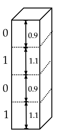
Several methods for embedding bits in 3D-printed objects have recently been proposed in the literature. These technologies allow the printer to vary either the orientation of the nozzle, the thickness of the layer, or the printing speed. Within reasonable bounds, varying either of those has a marginal effect on the functionality of the object. By varying layer thickness, for example, the printer can embed a by printing a layer that is slightly thinner, and a by printing a layer that is slightly thicker, than some reference thickness. By varying the orientation of the nozzle, bits can be embedded by the relative orientation of adjacent layers; for example, if two adjacent layers are oriented similarly, the embedded bit is , and otherwise it is . Both methods are illustrated in Figure 3.
Similar ideas have been implemented successfully in several recent works. Ref. [5] varies the thickness of each layer across several adjacent layers to create a matrix of bits that is visible to the naked eye on the surface of the object. Parity bits were then added to resolve reliability issues in some cases, and additional noise patterns were discussed, such as orientation issues and sanding. In the method LayerCode [17], variations in color and thickness were used to embed a barcode on the surface of the printed object, that can be retrieved using a smartphone camera.
An orientation-based method has been implemented in [18], where the authors print a reference layer that is circularly grooved by a sequence with low auto-correlation. Data is embedded in all other layers by the respective angle of the layer to the reference layer; this enables encoding with alphabet size larger than two.
Various other creative ideas have been explored. Examples include embedding information-carrying cavities within the object [19, 20], water-marking the 3D-mesh of the surface of the object [21], inserting RFID tags [8], inserting a series of notches which create an acoustic barcode when tapped [13], etc. In the data extraction phase, most existing methods rely on an RGB camera, a 3D scanner, or an ordinary scanner. Future technologies however, such as the ones in Figure 3, might require an industrial CT scanner.
However, we argue that none of these approaches is suitable for forensic applications. First, they all implicitly assume that a mechanism for correct information embedding is in place. Such a mechanism is crucial since in most scenarios the adversary owns the printer and/or the file, and might potentially remove the embedded bits altogether. Second, none of the methods is provably resilient to adversarial tampering; they can be easily breached by a knowledgeable adversary that can scrape the object or break it apart.
A different line of works applies machine-learning based methods to identify the intrinsic fingerprint which results from printer hardware imperfections (PrinTracker [16]). The variations of printer components arising from manufacturing errors are essentially inevitable, and create perceivable differences between objects made from different 3D-printers, even if they are printed from the same 3D model. These differences form a unique printer fingerprint, and can be extracted from the printed objects with commodity scanners.
Unlike the aforementioned techniques, PrinTracker is a fingerprinting solution which considers the adversarial nature of forensic applications, as well as potential attacks. This is different from the information embedding solution proposed in our work. Although information embedding can be used for fingerprinting purpose, it is not limited to it. The proposed solution allows for arbitrary bit embedding, which enables a variety of forensic applications. For example, certain applications may require the embedding of timestamp or geoposition of the printing into the printed object in order to check whether the printer has been misused in unauthorized time and location. Further, it remains to be shown if the extraction, storage, and identification of such imperfections scales well to a large number of printers.
2.3 Coding methods
Similar coding problems of information extraction from fragments have been previously studied in the literature, motivated by applications in DNA storage. In particular, several variations of the so-called torn-paper channel were studied in [22, 23, 24, 25, 26], where [22, 23, 24] focused on a probabilistic error model which is incompatible with our adversarial setting, and [25] studied an adversarial error model in which fragment are restricted in length. Most closely related, [26] studied -break codes, which coincide with our problem definition (given shortly). They provided a theoretical analysis of the fundamental limits, and an (almost) matching code construction. However, the scheme described in [26] involves random encoding and is only effective for a very large number of embedded bits. Our work herein addresses the same model of [26], yet at a much simplified framework which can be easily employed in practical settings, albeit below the maximum theoretical information rate.
3 Threat Model
We consider an knowledgeable adversary who wishes to commit a crime. The adversary is unable to obtain a certain required instrument, say, fails to pass background checks when attempting to purchase a firearm, or has insufficient financial means. Hence, the adversary manufactures the instruments independently, by downloading a 3D model file and feeding it to a commercial grade 3D-printer bought from a local electronics retailer.
We assume that the 3D printer, which does not require a background check to purchase, holds a binary string . The content of such string may include a unique printer ID, the time and geoposition of the printing process, the identity of the file, etc, which aid the authorities to trace the perpetrator111 In the upcoming experiments we focus solely on printer ID. The secure procurement and embedding of additional real-time identifying information is left for future studies. .
The string is embedded in every object printed by that printer, in an arbitrary fashion222Our methods are not inherently restricted to any particular bit embedding technique, as long as those bits are manifested as physical elements on the printing direction along the object. For the sake of experiments, we embed bits by varying layer heights.. We assume that the actuators (e.g., stepper motors) and other electronics (e.g., heater) of the 3D-printer are connected to a hardware platform (e.g., a control board) which supports a trusted execution environment (TEE). The TEE provides strong isolation on processor, memory, and peripherals (necessary for connecting the components). The connection from the board to the electronic components is also free of malicious tampering.
Meanwhile, the adversary is able to compromise the rich execution environment (REE) on the control board, including all necessary software components and the hosting operation system. Then, the adversary prints the object, commits the crime, and mechanically damages the printed tool, breaking it into at most fragments along the printing direction (i.e., the “” direction). The reasoning behind this assumption stems from the following observations.
-
1.
3D printers operate in a layer-by-layer fashion, and the 3D-prints have the lowest mechanical strength along the printing direction. If the break crosses multiple layers, then the irregular geometry of the broken section is likely to enable correct reassembly.
-
2.
The parameter reflects time constraints, access to instruments, or simply physical strength limitations, which prevent the adversary from breaking the object to arbitrarily many fragments. Hence, the parameter is expected to be small with respect to the number of embedded bits.
We assume the fragments of the broken instrument are confiscated by a law enforcement agency after the crime has been committed. The agency is able to read the embedded bits from the fragments by examining the height of each layer. Examples of equipment for this task includes microscopes and computed tomography (CT) devices. However, since the bit strings are extracted from at most fragments, the agency is not aware of their correct order.
4 SIDE Overview
SIDE incorporates coding-theoretic techniques with hardware isolation mechanism for secure information embedding and secure information extraction.
The resemblance between G-code and assembly code motivates the use of TEE to protect the integrity of the printing process. Indeed, both G-code and assembly code are instructions for lower-level hardware, but both are oblivious to the inner workings of that hardware. For example, an instruction to fetch memory data to a register does not specify how this operation is implemented in the integrated circuit (IC). Meanwhile, two ICs that support the same instruction set may have completely different circuit designs.
For secure extraction of information in case of breaks, the information goes through an encoding process before being embedded. The resulting codeword has the -break-resilient property; as the name suggests, the corresponding decoder is able to recover even if the codeword is sliced into at most unordered fragments.
Next, the SIDE slicer generates G-code with an embedded break-resilient codeword using some method (e.g., varying layer height), and the SIDE firmware executes the G-code, i.e., translates it to signals that directly operate the printer’s actuators. For secure embedding purposes, both the generation and the execution of the G-code are isolated in a trusted environment. Then, the result is forwarded to the peripherals that communicate with printer actuators; this process is also assumed to be protected by TEE.
5 Secure Information Extraction
5.1 Overview
The secure information extraction feature of SIDE is attributed to a break-resilient code (BRC), which is specifically developed for forensic fingerprinting purposes. BRC includes an encoder which holds a binary string (an information word, e.g., printer ID) for some integer , that is to be encoded to a string (a codeword). After encoding , the codeword is embedded in a printed object. BRC may be applied to any possible bit embedding method, and yet in Section 6.2 we focus on varying layer width. For a security parameter , an adversary breaks these bits at arbitrary locations or less, resulting in a multiset of at most fragments.
Example 1.
For a string and , the possible fragment multisets include
These bits are extracted from the fragments of the broken printed object, and then given to the decoder in an unordered fashion. The goal of the decoder is to reconstruct exactly in all possible cases, from which can be obtained, hereafter providing secure information extraction. The following notions from coding theory are employed as basic building blocks for BRC.
5.1.1 Systematic Reed-Solomon Codes
Systematic Reed-Solomon (RS) codes are a special type of Reed-Solomon codes, which have been widely employed in communication systems and data storage applications; for an introduction to the topic see [27, Ch. 5].
For integers and such that , a systematic RS code is a set vectors of length called codewords, each entry of which is taken from , a finite field with elements. The first entries of each codeword in a systematic RS code carry information in raw form, and the remaining contain redundant field elements that are used for error correction. This code is maximum distance separable (MDS), a property which allows the recovering of a codeword, after being corrupted by errors (incorrect symbols with unknown locations) and erasures (incorrect symbols with known locations), as long as .
Note that RS codes requires the finite field size to be greater or equal to the length of the codeword, i.e., . Furthermore, we focus on the binary field and its extension field in this paper, in which for some integer , and any element can be represented by a binary string of length .
5.1.2 Run-length Limited Codes
A run-length limited (RLL) code is a collection of codewords in which the length of runs of repeated bits is bounded. Specifically, in this paper we employ the RLL code from [28, Algorithm 1] for its simplicity of implementation.
5.1.3 Mutually Uncorrelated Codes
A mutually uncorrelated (MU) code has the property that for every two (possibly identical) codewords, the prefix of one is not identical to the suffix of another. As such, the codewords of a MU code do not overlap with each other when appearing as substrings of a binary string. MU codes has been extensively investigated in the past [29, 30, 31, 32, 33, 34, 35, 36, 37, 28].
We adopt a classic construction of MU code, in which each codeword starts with zeros followed by a one, where is the length of the (binary) information word. The last bit is fixed to one, and the remaining bits are free from zero runs of length .
5.1.4 Distinct Strings
Inspired by ideas from [28, Algorithm 1] and [38, Algorithm 1], we provide Algorithm 3 that maps an input word to an array of pairwise distinct binary strings, and offer the inverse operation in Algorithm 4. These procedures serve as an important component in BRC. Both algorithms, as well as proofs of their correctness, are given in the appendix.
5.2 Encoding
The encoding procedure of BRC is provided in Algorithm 1. Let be an information word, where
and where and are positive integers such that . The encoding of begins by prepending it with , resulting in
| (1) |
where is the binary representation of in bits (line 3). Then, as shown in line 4, the resulting string is fed into the function d-encode (which is implemented in Algorithm 3 in the appendix) and mapped to an array of pairwise distinct binary strings of length , i.e.,
| (2) |
Note that due to the implementation of d-encode, the first elements of dStrings remain intact, i.e., for all , and they are referred as markers. In the next step, a key-value store next is defined to represent the ordering of elements in dStrings as follows (line 6–10). For every key , the value is defined as
Note that is well defined, since for every by the pairwise distinct property of dStrings. It is also worth noting that the mapping from dStrings to next is injective; one may recover dStrings from next by observing every key such that , and connecting every two of them if .
We proceed to the treatment of next. Since the values in next are binary strings of length , they can be regarded as symbols in the finite field . They are sorted by the their corresponding keys and fed into a systematic Reed-Solomon encoder, which then generates redundancy strings (line 11). Note that such encoding is feasible since the codeword length is smaller than the number of elements in .
The codeword consists of two parts. The first region is called the information region, as it is generated from , which directly originate from the information word . The second region is called the redundancy region. As the name suggests, it is made from the redundant bits generated from next.
Define an encoding function mu which maps to a codeword of a mutually-uncorrelated code . The information region is hereby defined as
For , define the -th redundancy packet
as the concatenation of four redundancy strings. Then, define an encoding function rll which maps to a binary sequence that is free of zero runs of length or more, and introduces bits of redundancy. The encoding rll gives rise to the following lemma which is easy to prove.
Lemma 1.
For every , does not contain any codeword of .
The redundancy region is hereby defined as
Finally, the codeword is the two regions combined (line 12).
5.3 Decoding
Algorithm 2 provides a procedure for extracting the information word from at most fragments of the respective codeword . The crux of this decoding procedure is to reconstruct the key-value store next (see Section 5.2), and based on which the information word can be obtained. Specifically, the decoding algorithm creates a key-value store approxNext, which is slightly different from next, using the information which appears in the fragments. Alongside the correctly identified redundancy strings, approxNext goes through a Reed-Solomon decoding process and is corrected to next. Having the correct next in hand, the correct dStrings (Eq. (2)) can be found as described earlier. Then, dStrings is fed into d-decode (Alg. 4), which is the inverse process of d-encode (Alg. 3) to produce (Eq. (1)), whose suffix is the information word .
The decoding starts by distinguishing and decoding the discernible codewords of from the fragments. Let be a discernible codewords in which fully reside within one fragment, where is its respective decoding. If for some integer , it means that is a marker, and then the bits after it is a redundancy packet (line 4). As such, the decoder passes the bits after (if residing in the fragment) to an RLL-decoder and obtains four redundancy strings (line 5–6). The process stops once no more such codewords can be found, and we have the following lemma.
Lemma 2.
Let be the number of breaks that fall in the redundancy region of the codeword. Then, the decoding algorithm is guaranteed to obtain redundancy strings.
Proof.
The decoding algorithm may fail to obtain a redundancy packet due to the occurrence of a cut either in the packet itself, or in the preceding marker. Therefore, it is guaranteed to obtain redundancy packets, and hence redundancy strings. ∎
The other discernible codewords of , i.e., those encoded from non-markers (’s for ), are used to construct a key-value store approxNext. Initially, for every key (line 7). For each fragment , let
where and are (possibly empty) prefix and suffix of with no discernible codeword from that is encoded from a non-marker.
Then, in line 9, the decoder updates
for every . Note that approxNext is identical to next up to a bounded number of errors.
Lemma 3.
Let be the number of breaks that occur in the information region of the codeword. Then, approxNext differs from next at no more than positions.
Proof.
The decoding algorithm may fail to identify a non-marker (i.e., for ) in the information region if a break occurs inside it. Hence, the algorithm fails to identify at most non-markers. Notice that, failing to capture a non-marker affects at most two key-value pairs of next, i.e., and , and hence next and approxNext differ in at most positions. ∎
The decoding algorithm proceeds to correct the constructed approxNext to next, i.e., the key-value store generated in Algorithm 1 from , using the collected redundancy strings and a standard Reed-Solomon decoder (line 10). Note that the missing redundancy strings are erasures (line 3), since their locations are known. The success of the decoding process is guaranteed in the following theorem.
Theorem 1.
Line 10 outputs the correct key-value store next.
Proof.
Notice that in line 10, a codeword is constructed by coalescing the elements in next with redundancy strings , and fed into a Reed-Solomon decoder. By lemma 2, the decoder obtains at least redundancy strings, and as a result, the constructed codeword contains less than erasures.
Meanwhile, Lemma 3 implies that the number of key-value pairs in which next and approxNext differ is bounded by . Hence, the systematic part of the constructed codeword has at most errors. Recall that the encoding process generated redundancy strings (symbols in ), and hence the decoding in line 10 is guaranteed to be successful since
where the last transition follows since the actual number of breaks is at most the security parameter . The proof is concluded since a Reed-Solomon code can simultaneously correct errors and erasures as long as . ∎
6 Implementation
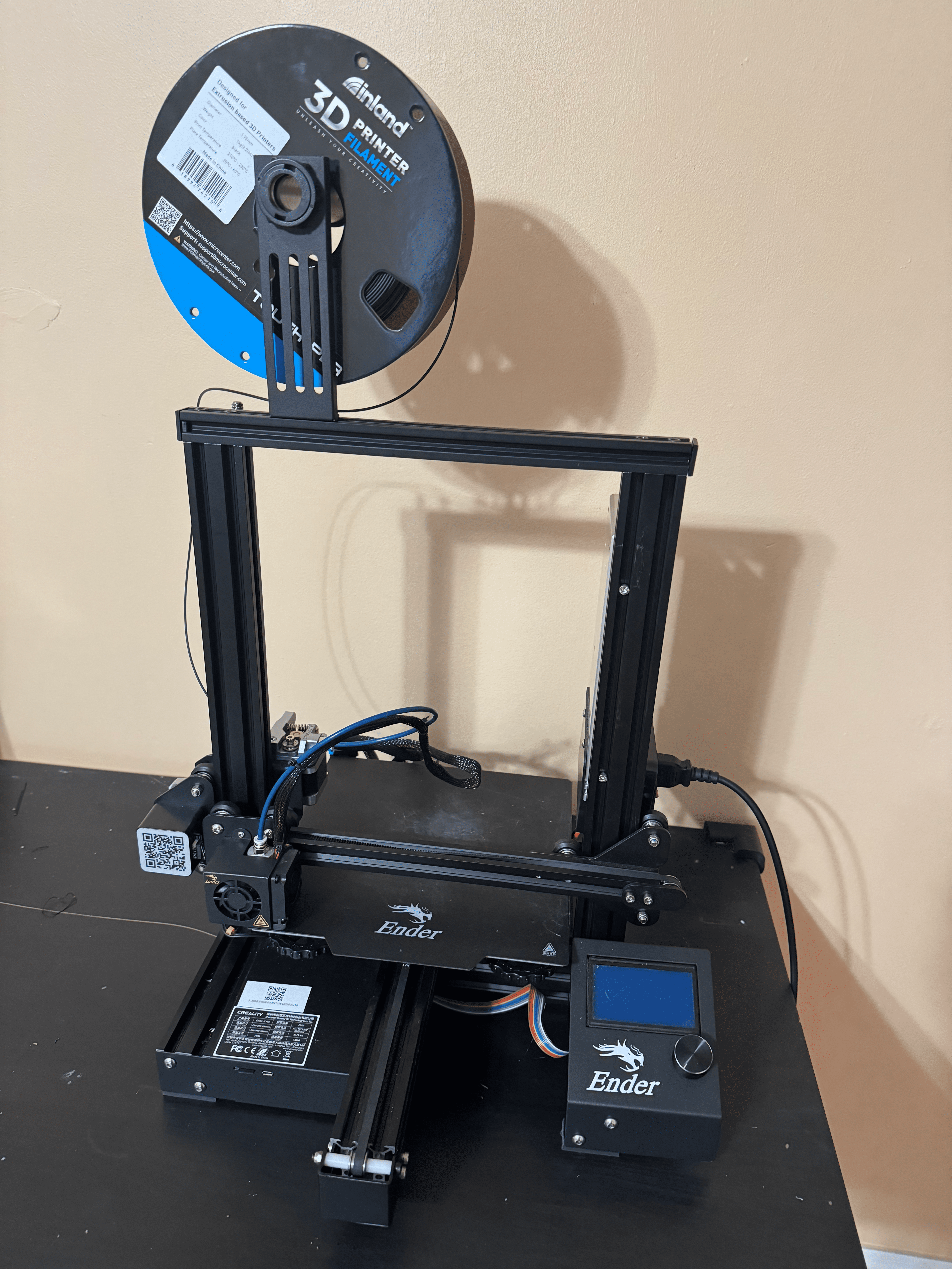
We implemented a prototype of SIDE and conducted experiments to validate its applicability. First, the information bits are encoded to a BRC codeword as described in Section 5.2. Then, we employ a Creality Ender 3 3D printer (Figure. 6(a)) to print objects with an embedded codeword (Figure 4(a)). The printer is operated by the Kipper firmware under the protection of OP-TEE. To read the information, a Leica S9D microscope is utilized to extract bits from the fragments of the printed object (Figure 4(b)). Note that reading externally using a visual device is not strictly necessary, as explained in the sequel. Finally, the bit strings that were recovered from the fragments go through the decoding process described in Section 5.3, and the original information is recovered.
6.1 BRC Encoding and Decoding
We implemented the BRC encoding and decoding procedures, whose pseudo-code is given in Algorithm 1 and Algoritm 2, respectively. The encoding part is written in C++ for the ease of using TEE. The implementation details and the use of TEE will be described in the future version of this paper. The decoding part is implemented in Python.


6.2 Information Embedding and Extraction
We argue that any practical bit embedding method should satisfy the following three properties.
-
1.
Readability: The embedded information is readable within reasonable costs.
-
2.
Robustness: The embedded information cannot be easily destroyed.
-
3.
Obliviousness: The embedding method is oblivious to both the information bits and the geometry of the printed object.
The readability requirement implies economical reading of bits from the broken object with respect to a given use case. The robustness requirement states that the embedded information must be sufficiently robust against adversarial tempering, within a certain bound. For example, the surface of the printed object may be easily abraded and as a result, embedding information on the surface is not robust.
The obliviousness requirements decouples the embedding method both from the information to be embedded and from the 3D models. Examples which violate the obliviousness requirement include representing ’s by thick layers and representing ’s by thin layers; this will cause codewords with different number of 1’s to have embeddings of different lengths. Moreover, embedding bits by alerting the geometry of the printed object is also considered inappropriate, as it may significantly affect its functionality. Note that for any embedding method, imposing some requirement on the dimension of the 3D model is inevitable (e.g., that its size is sufficient for embedding a certain number of bits), and we do not consider this as a violation of the obliviousness requirement.
In our implementation we embed bits by varying layer width of the printed object, with a slight modification. As shown in Figure 5, a is represented by three layers of millimeters, and a is represented by two layers of millimeters. These values are chosen to maximize information density, i.e., the number of bits that can be embedded per unit length, with respect to the minimum layer height ( millimeters) offered by the Ender 3 printer used in the experiments. As the heights add up to millimeters in both cases, this method avoids the situation of height discrepancy mentioned in the previous paragraph, and satisfies the obliviousness requirement. As for the robustness requirement, we note that layer height is an intrinsic property of the printed object, and cannot be easily altered, nor it is affected by breaking or scraping the object.
The reading of information from fragments of the printed object is done by a Leica S9D microscope, which provides a high resolution that captures their rugged surface. It is worth noting that the reading of bits does not require the surface of the fragment to be free of adversarial tempering, as less-economical solutions, e.g., using an industrial CT scanner, can be used to infer the layer width via tomographic analysis.
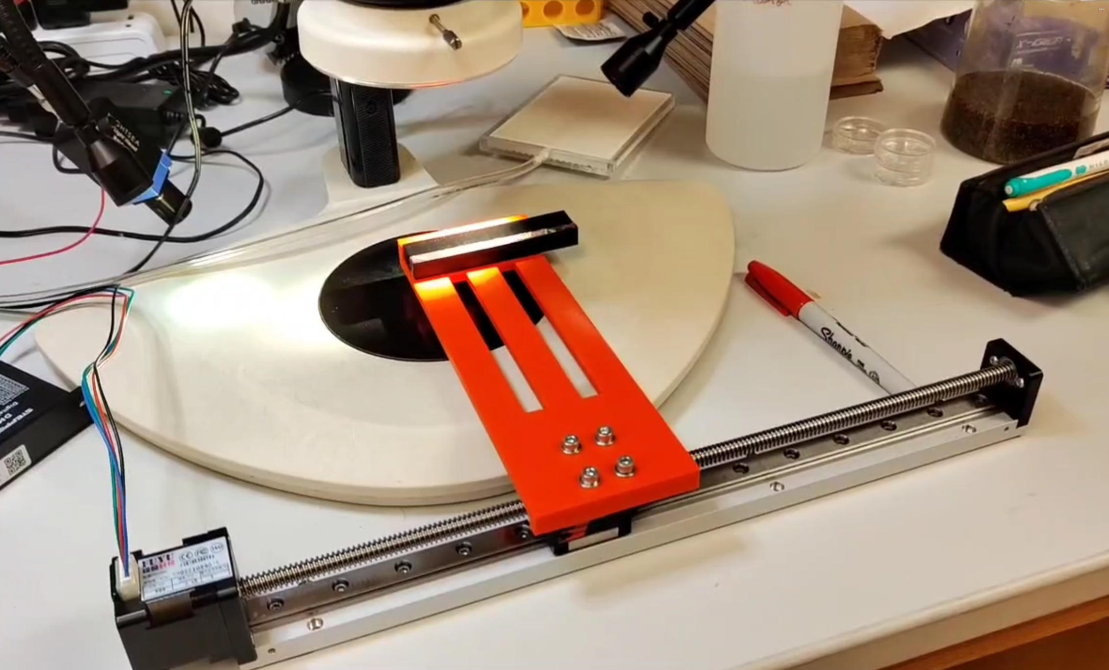
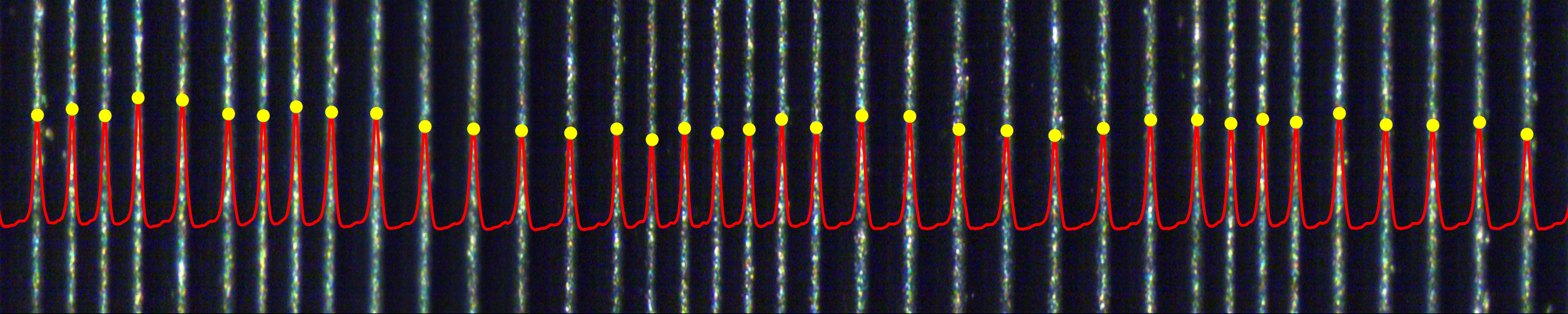
Due to the limitation of field of view, the microscope is unable to capture the entire fragment all at once. To address this, the fragment to be examined is fixed on a motorized rail slider (see Figure 6(b)). During the information extraction process, the fragment slides over the field of view of the microscope, which takes series of pictures in the meantime. Note that the pictures are taken so that every two consecutive pictures overlap. This feature allows us to fuse them together and obtain a picture of the entire fragment using ImageJ with the stitching plugin [39].
In the resulting stitched image, shown in Figure 7, the bright lines are the center of each layer. To automatically read the bits from this image, we implemented a program that reads the distance between every two adjacent lines, and places them in an array. Recall that there are two types of layers, the thin ( mm) and the thick ( mm). Hence, the elements in the array can be placed in three categories, i.e., two adjacent thin layers (thin-thin), a thin layer followed by a thick one or vice versa (thin-thick), and two adjacent thick layers (thick-thick). The program then applies -means clustering with in order to differentiate the three categories.
Next, the program examine the clustering results and corrects potential errors resulting from the lighting environment during microscope reading or the image distortion in stitching. The embedding method (Figure 5) imposes certain patterns, which allow such correction. For example, a thin-thin distance must appear adjacent to another thin-thin distance, and in between thin-thin and thick-thick there must be a thin-thick.
For each layer, the program determines whether it is a thick one or a thin one by the distances from its adjacent lines, e.g., a thin line may have a thick-thick distance on its left and a thick-thin distance on its right. This concludes the reading of bits from fragments.
| # of breaks | information length | codeword length | information rate | object length | information density |
|---|---|---|---|---|---|
| 1 | 98 bits | 243 bits | 0.403 | 87.48 mm | 1.089 bits/mm |
| 2 | 120 bits | 353 bits | 0.340 | 127.08 mm | 0.944 bits/mm |
7 Evaluation
The evaluation of our prototype focuses on the information density (number of bits per unit distance, which is directly affected by the codeword length of BRC) and the recoverability of data from broken objects. The former measures the amount of information that can be embedded in an given object, and the latter provides the secure information extraction feature of SIDE.
On the theoretical side, we analyzed the growth of the codeword length as a function of and , for and (Figure 8). On the engineering side, we conduct experiments on two groups of samples, which differ in the number of embedded bits (reflected by ) and the number of breaks that can be tolerated (reflected by ).
For the first group, we printed five sample cuboids of dimension mmmmmm, and implemented a -break code with and , which maps an information word of bits to a bit codeword. For each cuboid, we prepared a distinct information string and encoded it to a codeword of the aforementioned -break code; the codeword is embedded in the cuboid and is decodable even if broken at most once at any arbitrary location. For the second group, we develop a -break code with and . The sample cuboids in this group has a dimension of mmmmmm. The cuboids in this group are resilient to two breaks in any arbitrary location. Table I details the parameters of both groups.
For every cuboid, we broke it apart by hand into parts, where is the number of breaks to which it is resilient. We examined the fragments and read bits (see Section 6.2). We assumed that the orientation of the fragments (i.e., the correct direction) is known to the decoder; we postulate that closer examination of individual layers can alleviate this assumption due to the impact of gravity on the molten thermoplastic, and leave this to future work. The bit strings from the fragments were fed into the decoding algorithm, and the decoding results are compared against the original encoded data. The information extraction succeeded in all ten cases.
8 Conclusion
In this paper, we present SIDE, which aims to provide secure information embedding and extraction in forensic 3D fingerprinting against the malicious tempering of both 3D printers and the printed objects. SIDE is built upon hardware isolation mechanisms and coding-theoretic techniques. we develop break-resilient code, which allows for information extraction from the printed object even if it is broken into pieces. We leverage trusted execution environment to protect the integrity of the printing process, which guarantees the embedding of the break-resilient codeword. We implement a prototype of SIDE and validated our design.
Finally, we propose future studies in order to advance secure 3D fingerprinting technology further. On the engineering side, we propose to study the integration of trusted execution environments in commodity printers, and the trusted procurement of bits (e.g., timestamp or geolocation) for the sake of embedding. Another engineering challenge is coming up with alternative secure methods for bit embedding in order to increase information density. On the theoretical side we propose to devise practical coding methods which operate closer to the information-theoretic limits of this model [26], as well as more sophisticated methods for reconstructing the information from only a subset of fragments, rather than all of them.
9 Acknowledgment
This research was supported by the National Science Foundation under Grant CNS-2223032.
References
- [1] Marrian Zhou “3D-printed gun controversy: Everything you need to know” accessed Sep. 15st, 2023, https://www.cnet.com/news/politics/the-3d-printed-gun-controversy-everything-you-need-to-know/ In CNET, 2018
- [2] Hannah Jiang and Tam Hunt “Untraceable ‘ghost guns’ are easier than ever to 3D print — we went inside a company that helps people do it” accessed (Oct. 21st, 2021), https://news.yahoo.com/untraceable-ghost-guns-easier-ever-150015562.html In Insider Magazine, 2021
- [3] Connor M McNulty, Neyla Arnas and Thomas A Campbell “Toward the printed world: Additive manufacturing and implications for national security” In Defense Horizons National Defense University Press, 2012, pp. 1
- [4] Jon Fingas “Security firm claims to thwart iPhone X’s Face ID with a mask” accessed Sep. 15st, 2023, https://www.engadget.com//2017-11-11-security-firm-claims-to-defeat-face-id-with-mask.html In ENGADGET, 2019
- [5] Arnaud Delmotte, Kenichiro Tanaka, Hiroyuki Kubo, Takuya Funatomi and Yasuhiro Mukaigawa “Blind watermarking for 3-D printed objects by locally modifying layer thickness” In IEEE Transactions on Multimedia 22.11 IEEE, 2019, pp. 2780–2791
- [6] Masahiro Suzuki, Pailin Dechrueng, Soravit Techavichian, Piyarat Silapasuphakornwong, Hideyuki Torii and Kazutake Uehira “Embedding information into objects fabricated with 3-D printers by forming fine cavities inside them” In Electronic Imaging 2017.7 Society for Imaging ScienceTechnology, 2017, pp. 6–9
- [7] Karim A ElSayed, Adam Dachowicz and Jitesh H Panchal “Information embedding in additive manufacturing through printing speed control” In Proceedings of the 2021 Workshop on Additive Manufacturing (3D Printing) Security, 2021, pp. 31–37
- [8] Jeffrey Voris, Benjamin Foster Christen, Jorge Alted and David W Crawford “Three dimensional (3d) printed objects with embedded identification (id) elements” US Patent 9,656,428 Google Patents, 2017
- [9] J., C.., A. and D. “Product authentication” U.S. Patent App. 14/250,533, 2015
- [10] J. Wee, C.. Byatte, A. and D. “Objets de vertu” U.S. Patent App. 14/485,880, 2015
- [11] Chao Wei, Zhe Sun, Yihe Huang and Lin Li “Embedding anti-counterfeiting features in metallic components via multiple material additive manufacturing” In Additive Manufacturing 24 Elsevier, 2018, pp. 1–12
- [12] Fei Chen, Yuxi Luo, Nektarios Georgios Tsoutsos, Michail Maniatakos, Khaled Shahin and Nikhil Gupta “Embedding tracking codes in additive manufactured parts for product authentication” In Advanced Engineering Materials 21.4 Wiley Online Library, 2019, pp. 1800495
- [13] Chris Harrison, Robert Xiao and Scott Hudson “Acoustic barcodes: passive, durable and inexpensive notched identification tags” In Proceedings of the 25th annual ACM symposium on User interface software and technology, 2012, pp. 563–568
- [14] Muhammad Usama and Ulas Yaman “Embedding Information into or onto Additively Manufactured Parts: A Review of QR Codes, Steganography and Watermarking Methods” In Materials 15.7 MDPI, 2022, pp. 2596
- [15] Karim A ElSayed, Adam Dachowicz, Mikhail J Atallah and Jitesh H Panchal “Information Embedding for Secure Manufacturing: Challenges and Research Opportunities” In Journal of Computing and Information Science in Engineering 23.6 American Society of Mechanical Engineers Digital Collection, 2023
- [16] Zhengxiong Li, Aditya Singh Rathore, Chen Song, Sheng Wei, Yanzhi Wang and Wenyao Xu “PrinTracker: Fingerprinting 3D printers using commodity scanners” In Proceedings of the 2018 ACM sigsac conference on computer and communications security, 2018, pp. 1306–1323
- [17] Henrique Teles Maia, Dingzeyu Li, Yuan Yang and Changxi Zheng “LayerCode: Optical Barcodes for 3D Printed Shapes” In ACM Trans. Graph. 38.4 New York, NY, USA: Association for Computing Machinery, 2019 DOI: 10.1145/3306346.3322960
- [18] Jong-Uk Hou, Do-Gon Kim, Sunghee Choi and Heung-Kyu Lee “3D Print-Scan Resilient Watermarking Using a Histogram-Based Circular Shift Coding Structure” In Proceedings of the 3rd ACM Workshop on Information Hiding and Multimedia Security, IH&MMSec ’15 Portland, Oregon, USA: Association for Computing Machinery, 2015, pp. 115–121 DOI: 10.1145/2756601.2756607
- [19] Karl D.. Willis and Andrew D. Wilson “InfraStructs: Fabricating Information inside Physical Objects for Imaging in the Terahertz Region” In ACM Trans. Graph. 32.4 New York, NY, USA: Association for Computing Machinery, 2013 DOI: 10.1145/2461912.2461936
- [20] Dingzeyu Li, Avinash S. Nair, Shree K. Nayar and Changxi Zheng “AirCode: Unobtrusive Physical Tags for Digital Fabrication” In Proceedings of the 30th Annual ACM Symposium on User Interface Software and Technology, UIST ’17 Québec City, QC, Canada: Association for Computing Machinery, 2017, pp. 449–460 DOI: 10.1145/3126594.3126635
- [21] Jae-Won Cho, Rmy Prost and Ho-Youl Jung “An Oblivious Watermarking for 3-D Polygonal Meshes Using Distribution of Vertex Norms” In IEEE Transactions on Signal Processing 55.1, 2007, pp. 142–155 DOI: 10.1109/TSP.2006.882111
- [22] Ilan Shomorony and Alireza Vahid “Communicating over the torn-paper channel” In IEEE Globecom, 2020, pp. 1–6
- [23] Ilan Shomorony and Alireza Vahid “Torn-paper coding” In IEEE Trans. Inf. Theory 67.12 IEEE, 2021, pp. 7904–7913
- [24] Aditya Narayan Ravi, Alireza Vahid and Ilan Shomorony “Capacity of the torn paper channel with lost pieces” In Proc. IEEE Int. Symp. Inf. Theory, 2021, pp. 1937–1942 IEEE
- [25] Daniella Bar-Lev, Sagi Marcovich Eitan Yaakobi and Yonatan Yehezkeally “Adversarial torn-paper codes” In IEEE Trans. Inf. Theory IEEE, 2023
- [26] Canran Wang, Jin Sima and Netanel Raviv “Break-Resilient Codes for Forensic 3D Fingerprinting”, 2023 arXiv:2310.03897 [cs.IT]
- [27] Ron M Roth “Introduction to coding theory” In IET Communications 47.18-19 IET, 2006, pp. 4
- [28] Maya Levy and Eitan Yaakobi “Mutually uncorrelated codes for DNA storage” In IEEE Transactions on Information Theory 65.6 IEEE, 2018, pp. 3671–3691
- [29] V Levenshtein “Decoding automata invariant with respect to the initial state” In Problems of Cybernetics 12, 1964, pp. 125–136
- [30] V Levenshtein “Maximum Number of Words in Codes without Overlaps” In Problemy Peredachi Informatsii 6.4, 1970, pp. 355–357
- [31] E. Gilbert “Synchronization of binary messages” In IRE Transactions on Information Theory 6.4, 1960, pp. 470–477 DOI: 10.1109/TIT.1960.1057587
- [32] Dragana. Bajic and J. Stojanovic “Distributed sequences and search process” In 2004 IEEE International Conference on Communications (IEEE Cat. No.04CH37577) 1, 2004, pp. 514–518 Vol.1 DOI: 10.1109/ICC.2004.1312542
- [33] Dragana Bajic and Tatjana Loncar-Turukalo “A simple suboptimal construction of cross-bifix-free codes” In Cryptography and Communications 6.1, 2013, pp. 27–36 DOI: 10.1007/s12095-013-0088-8
- [34] Yeow Meng Chee, Han Mao Kiah, Punarbasu Purkayastha and Chengmin Wang “Cross-Bifix-Free Codes Within a Constant Factor of Optimality” In IEEE Transactions on Information Theory 59.7, 2013, pp. 4668–4674 DOI: 10.1109/TIT.2013.2252952
- [35] Stefano Bilotta, Elisa Pergola and Renzo Pinzani “A New Approach to Cross-Bifix-Free Sets” In IEEE Transactions on Information Theory 58.6, 2012, pp. 4058–4063 DOI: 10.1109/TIT.2012.2189479
- [36] Simon R. Blackburn “Non-Overlapping Codes” In IEEE Transactions on Information Theory 61.9, 2015, pp. 4890–4894 DOI: 10.1109/TIT.2015.2456634
- [37] Geyang Wang and Qi Wang “Q-Ary Non-Overlapping Codes: A Generating Function Approach” In IEEE Transactions on Information Theory 68.8, 2022, pp. 5154–5164 DOI: 10.1109/TIT.2022.3167845
- [38] Ohad Elishco, Ryan Gabrys, Eitan Yaakobi and Muriel Médard “Repeat-Free Codes” In IEEE Transactions on Information Theory 67.9, 2021, pp. 5749–5764 DOI: 10.1109/TIT.2021.3092056
- [39] Stephan Preibisch, Stephan Saalfeld and Pavel Tomancak “Globally optimal stitching of tiled 3D microscopic image acquisitions” In Bioinformatics 25.11, 2009, pp. 1463–1465 DOI: 10.1093/bioinformatics/btp184
.1 Distinct Strings
Alg. 3 offers a procedure that maps an input word to dStrings, which is an array of pairwise distinct binary strings of length . Besides, the inverse operation, as given in Alg. 4, outputs given the array dStrings.
The encoding algorithm first appends a to (line 3), and as a result, . The word is segmented to intervals of length and placed in a tentative array dStrings (line 4). The segments are not necessarily pairwise distinct at this point, and they are referred as the original.
The encoding algorithm continues to look for identical original segments, deletes one of them, and appended a new binary string to dStrings; this new string contains the indexing information of the two identical binary strings which allows for decoding at a later point in time. Moreover, we end every new string with a to distinguish it from the right most original segment which ends with a .
With indices and initially set to and , the algorithm looks up every index for a match, i.e., is identical to (line 7). Once a match is found, the latter is deleted from dStrings (line 9) and the indices are recorded in a binary string to be placed at the end of dStrings, which is responsible for the recovery of the deleted entry.
Note that, naïvely defining the new strings as the concatenation of binary representations of and may introduce more repeated strings; it may coincide with existing elements in dStrings. To address this issue, the algorithm starts looking for an alternative binary representation of which is not identical to the first bits of every existing element in dStrings.
Starting from , the following procedure is repeated times. In each time, is increased by (line 13). Then, it continues to increase until its binary representation in bits does not coincide with the first bits of every existing element in dStrings (line 14). One may imagine this process as looking for the -th available parking slot in a row, in which some have been occupied (unavailable). A slot is unavailable if the binary representation of its index coincides with the first bits of any element in dStrings. Otherwise, it is available. Starting for index , is indeed the index of the -th available slot.
Note that when the repetition stops, equals to the sum of and the number of times the condition in line 14 was true. Recall that , and the latter equals to the number of unavailable slots that may be encountered during the increment of , which is at most since there are only elements in dStrings. Therefore, and can be represented by bits.
Therefore, we use the binary representation of in to serve as the alternative representation of . It is concatenated with the binary representation of (in bits since ) and sufficiently many ’s to make a new string (line 15). The new string is appended to dStrings, and is different from every other element in the first bits; this fact gives the following lemma.
Lemma 4.
The new binary string being appended in line 15 is different from every existing elements in dStrings.
Lemma 4 allows us to decrease by one (line 16) since there is no need to compare with element whose index is greater than . The algorithm terminates when there is no elements of dStrings remains to be compared (line 5), and its output satisfies the following.
Theorem 2.
Alg. 3 outputs an array dStrings of pairwise distinct binary strings of length-.
Proof.
Assume, for sake of contradiction, that there exist and such that . If is a new string constructed in line 15, then it is distinct from every other elements on its left by Lemma 4, a contradiction. If is not a new string, then the on its left is not as well. As such, would have been deleted in line 9 when and , a contradiction. ∎
We proceed to introduce the decoding procedure, which is essentially the inverse operation of the encoding process. Given the array dStrings, the decoding algorithm reads from the rightmost element if it is a constructed new string, i.e., if last bit of which is (line 3). Recall that a new string is created when two identical strings is found, with being the index of the first one (the reference) and being the alternative index of the second (the referent).
Line 4 reads the value of , and line 5 reads the value of . Recall that is the index of the -th available slots in a row. Hence, the variable is initially set to , and then subtracted by the number of unavailable slots with indices less than to reaches the actual index of the referent (line 6–7). Together, enable the recovery of the referent, and the rightmost element is deleted (line 8). Once all new strings have been consumed in the aforementioned process, the decoding is concluded and is returned (line 10).