1.3pt
A Precision Drone Landing System using Visual and IR Fiducial Markers and a Multi-Payload Camera
Abstract
We propose a method for autonomous precision drone landing with fiducial markers and a gimbal-mounted, multi-payload camera with wide-angle, zoom, and IR sensors. The method has minimal data requirements; it depends primarily on the direction from the drone to the landing pad, enabling it to switch dynamically between the camera’s different sensors and zoom factors, and minimizing auxiliary sensor requirements. It eliminates the need for data such as altitude above ground level, straight-line distance to the landing pad, fiducial marker size, and 6 DoF marker pose (of which the orientation is problematic). We leverage the zoom and wide-angle cameras, as well as visual April Tag fiducial markers to conduct successful precision landings from much longer distances than in previous work (168m horizontal distance, 102m altitude). We use two types of April Tags in the IR spectrum – active and passive – for precision landing both at daytime and nighttime, instead of simple IR beacons used in most previous work. The active IR landing pad is heated; the novel, passive one is unpowered, at ambient temperature, and depends on its high reflectivity and an IR differential between the ground and the sky. Finally, we propose a high-level control policy to manage initial search for the landing pad and subsequent searches if it is lost – not addressed in previous work. The method demonstrates successful landings with the landing skids at least touching the landing pad, achieving an average error of 0.19m. It also demonstrates successful recovery and landing when the landing pad is temporarily obscured.
Index Terms:
drone, autonomous, landing, fiducial, infrared, gimbal, long-distance, nighttimeI Introduction
Takeoff and waypoint-to-waypoint navigation have been reliably automated in drone flight, with global positioning system (GPS) as the main navigational tool. Drones can generally execute missions safely even with typical GPS errors of 1m or more [1] because they tend to operate in free airspace away from obstacles. However, this error becomes problematic during the landing process, when the drone may have to operate in a constrained space due to obstacles or other restrictions. While it is possible to decrease GPS error using real-time kinematic (RTK) systems, these are not available at every landing site, and GPS itself is not even always available. Furthermore, GPS-based landings are blind to the environment and therefore cannot intelligently avoid obstacles.
A common way of improving GPS landings is to mark the landing pad with an indicator that makes it possible to detect with sensors onboard the drone, and then carry out a landing precisely on the landing pad. One such indicator is a fiducial marker – a 2D, high-contrast pattern that marks significant objects or locations. Fiducial systems such as April Tag [2], AR Tag [3], ArUco [4], and WhyCode [5] provide reliable, low false-positive identification of distinct markers via an encoded ID number. They extract the pose (position and orientation) of the markers relative to a camera using monocular images, the camera’s distortion parameters, and the size of the fiducial marker. While the position is straightforward to compute, the orientation is subject to ambiguity [6], leading to erroneous output [7]. Similarly, infrared (IR) beacons actively create a signal that can be recognized using an IR camera, which is also a common drone peripheral sensor. IR beacons provide a means of estimating the pixel position of a landing pad in a camera feed, and in some cases provide a distance estimate.
A simple way of identifying landing pads marked with fiducial markers or IR beacons is to mount a downward-facing camera on the drone to determine its relative position to the landing pad if the drone is already in a limited space above the landing pad. However, detecting marked landing pads is difficult if the camera is rigidly mounted to the drone because of the drone’s motion. Further, even if it is mounted on a stabilized gimbal, the system may lose sight of the landing pad, e.g., if the wind blows it off course. This difficulty has led to a strategy of actively tracking the marker independently of the drone’s motion, which increases the reliability of the detection. However, this strategy complicates the estimation of the relative pose from the drone to the landing pad, such that it requires more data to determine (e.g., the camera’s orientation, the drone’s altitude above ground level (AGL), or the straight-line distance from the camera to the landing pad) or sophisticated ground infrastructure (e.g., collaborative, intelligent landing pads or augmented fiducial systems). Such extra requirements restrict the drone’s hardware and landing behavior.
We contribute a precision drone landing method with a gimbal-mounted, multi-payload camera that minimizes data requirements, primarily using the direction from the drone to the landing pad as measured by the gimbal and its camera. Previous work tends to require at least one of the following: the drone’s AGL, the straight-line distance to the landing pad, physical marker size, or marker pose. Minimizing the required data enables the method to switch between different cameras and landing pads with minimal reconfiguration, whereas previous work depends on static systems. We use a zoom camera for long-range detection, a wide-angle camera for short-range detection, and an IR camera for both daytime and nighttime detection. We mark landing pads with fiducial markers (April Tags) in both the visual and IR spectra (instead of previously-used IR beacons), allowing the system to distinguish between different landing pads in the IR spectrum reliably. We test an active, heated IR April Tag and a novel, unheated, high-reflectivity April Tag for landing infrastructure that is usable at nighttime without power. Finally, we develop a control policy for approaching and landing on the landing pad that manages the initial search for the landing pad and subsequent searches if the landing pad is lost during approach or descent.
II Related Work
The most basic paradigm of autonomous landing with a camera and a marked landing pad assumes the camera has a downward-facing orientation, either rigidly mounted to the drone or stabilized vertically down on a gimbal. Araar et al. use downward-facing cameras and the 6 degrees of freedom (DoF) pose of an April Tag, encountering issues of orientation ambiguity, and solving them by using many markers and a voting scheme to decide the position of the landing pad [8]. Olivarez-Mendez et al. use a camera fixed to a helicopter to locate a custom visual marker on a stationary platform, approaching from a distance of 4m and achieving an error of 0.7m [9]. Badakis et al. use a downward facing camera to locate an ArUco marker with an embedded IR beacon and measure the drone’s height using a barometer and rangefinder. They achieve an average error of 0.15m when using both the visual and IR systems, and an error of 0.25m when using only one system [10]. Nowak et al. use an IR beacon on the landing pad and light detection and ranging (LiDAR) to determine the drone’s height, achieving successful landing on a 0.4m by 0.4m platform [11]. Xuan-Mung et al. use an IR beacon mounted on a landing pad that is heaving to mimick a ship’s motion and detect it using a downward-facing IR camera [12]. Instead of using a marker or beacon, Pluckter and Scherer record the appearance of the takeoff location and realign the drone with it using visual matching after executing a mission [13]. Polvara et al. use a fixed, forward-facing camera for initial approach, and a fixed, downward-facing camera for final descent. Their system collaborates with the moving landing pad (marked with an AR Tag) to share GPS position, velocity, and acceleration data (in simulation) [14]. Falanga et al. use a custom marker, one downward-facing camera, and one forward-facing camera to land on a 1.5m by 1.5m platform marked with a custom visual marker [15]. While this paradigm is employed successfully, it suffers from the basic weakness that it is difficult to detect and maintain detection of the marker if the camera is fixed or only pointing downward because the camera moves according to the movements of the drone. Additionally, the camera’s limited field of view makes it difficult to find the marker if it cannot move independently.
Another paradigm of autonomous landing uses a gimbal-mounted camera that is actuated to track the landing pad independently of the drone’s orientation, which increases the robustness of the landing pad detection but complicates the landing process. Borowczyk et al. present a hybrid method that uses a collaborative GPS system (both on the moving landing pad and the drone) for long-range approach, a gimbal-mounted camera for initial visual approach, and a downward-facing, wide-angle camera for final descent [16]. Cho et al. use a gimbal-mounted camera to detect the 6 DoF pose of an AR Tag on a moving ship deck, initially approaching using the GPS data of both the ship and the drone, and achieving an error of 0.2m [17]. Jiang et al. use a gimbal-mounted camera to track a landing pad with a custom visual marker and approach it using the gimbal angles and height as measured by an altitude sensor [18]. Demirhan and Premachandra use a gimbal-mounted camera to detect a custom visual marker and approach using the camera’s orientation, the marker’s pose, and the drone’s AGL, measured by an auxiliary sensor [19]. Lim et al. use an omnidirectional IR beacon mounted on the landing pad and approach it using the gimbal-mounted camera’s attitude and the drone’s height as measured from a LiDAR [20]. They can detect and approach from a distance of 18m. Tanaka et al. use the full 6 DoF pose of the marker – normally subject to orientation ambiguity – by creating a proprietary version of AR Tag called Lentimark [21], which has wave-like patterns on its side to make the rotation unambiguous [22]. Our previous studies evaluate several fiducial systems to empirically test the effect of pose ambiguity on the behavior of the drone [7, 23], determining that it leads to erroneous control signals and erratic behavior, but that some systems still produce succesful landings.
Some studies have created fiducial markers in the IR spectrum. Dogan et al. have used 3D-printed ArUco markers and QR codes to unobtrusively mark objects for augmented reality [24]. Khattack et al. have used laser-cut, acrylic ArUco markers for drone localization in visually degraded environments [25]. Claro et al. created a multimodal, active thermal marker based on ArTag for autonomous landing of a drone with global navigation satellite system (GNSS), RTK, LiDAR and visual and thermal cameras, achieving an error of 0.03m and using a downward-facing camera on a stabilized gimbal [26]. The marker is composed of two materials of differing reflectivities, with one heated and one unheated.
Most of the related work depends on the AGL or range (straight-line distance to the landing pad) which must be measured by auxiliary sensors, e.g., LiDAR or ultrasonic sensors. AGL may not correspond directly to the altitude above the landing pad if the terrain is not flat, such that the system may miscalculate the position of the drone relative to the landing pad. The method described in [18] is similar to what we propose, but we improve upon it by not requiring the height, by adapting it to multiple cameras, and by using IR fiducial markers. Additionally the IR beacons are not necessarily distinguishable from each other – often characterized simply by areas of significant IR radiation, such that any IR emission might appear as a landing pad [11, 12]. This issue is partially addressed in [26], with an actively heated marker and a downward-facing camera, but we believe there is also potential in using actuated cameras and passive IR infrastructure that exploits high reflectivity. Finally, most of the related work does not focus on the initial search for the landing pad or on detection re-acquisition if it is lost. Instead, it treats autonomous landing as a low-level control problem, detailing methods for sensor fusion and filtering to develop reliable pose estimation and trajectory calculation. However, many modern drones make this unnecessary by providing position or velocity modes that execute high-level commands, e.g., forward x m/s, using either GPS or optical flow for velocity measurement. Furthermore, many of the methods depend on expensive, sophisticated, or collaborative ground infrastructure, whereas we minimize the required data and sensors.
III System Overview
III-A Required Data and Processing
In our proposed method, we primarily consider the pan angle and the tilt angle from the drone’s heading to the landing pad (see Fig. 1). Secondarily, we consider the difference between the drone’s yaw and the landing pad’s yaw, and the pixel size of the landing pad (queried from the fiducial system), and the zoom factor (queried from the flight controller). We use to point the drone in the same direction as the landing pad before descent, and we direct control state transitions and conduct intermediate calculations based on and . We avoid using the altitude above ground level (AGL) and the straight-line range from the drone to the landing pad because these are not available on many drones. Additionally, the AGL may not equal the altitude above the landing pad, e.g., on rough terrain, making any resulting calculations unreliable.
We determine and by tracking the landing pad with a gimbal-mounted camera and comparing its orientation to that of the drone. Since the gimbal is often not aimed directly at the landing pad, but skewed by some angle as a result of the drone’s motion, we also consider the angles implied by the landing pad’s pixel position in the camera frame. Therefore, and are calculated as in Equations (1) and (2), where and represent the relative tilt and pan of the gimbal, and and represent the additional relative pan and tilt implied by the landing pad’s pixel positions.
| (1) |
| (2) |
We query and from the flight controller and calculate and by normalizing the landing pad’s pixel positions into the interval and multiplying by the field of view in the relevant dimension, as in Equation (3). Here, is the horizontal pixel center of the landing pad, is the center pixel of the camera’s horizontal dimension, and is the camera’s horizontal field of view. We conduct a similar calculation for the vertical dimension, with , , and .
| (3) |
We calculate the horizontal field of view for each camera using Equation (4) [27], where is the camera’s focal length and is its sensor width. For cameras with a fixed focal length , we use ; otherwise, we use , where is the zoom factor and is the base focal length. We conduct a similar calculation for the vertical field of view with the sensor height instead of .
| (4) |
Calculating and in this way allows the system to switch between cameras and zoom factors, such that it can identify and track the landing pad from long distances using the zoom camera, and then continually zoom out as it approaches.
III-B Control Policy
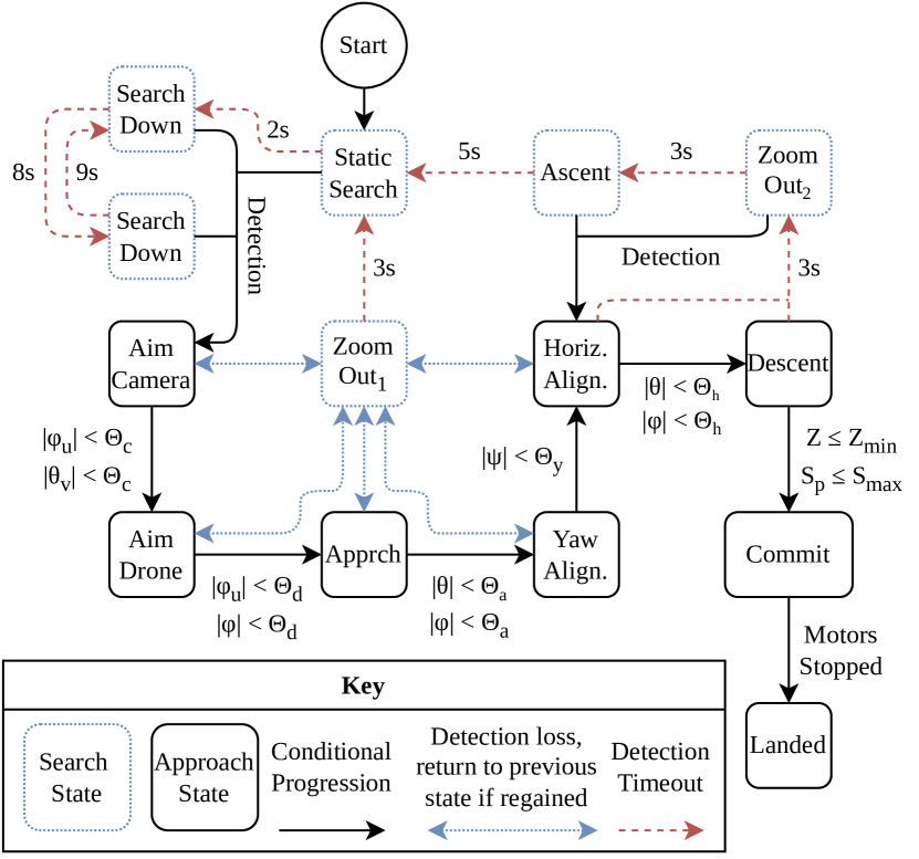
The autonomous landing system follows the control policy outlined in Fig. 2. We assume the drone starts the landing process near – but not directly above – the landing pad, having navigated via GPS or some other means. It starts to look for the marker by holding the camera still, facing forward and down (static search). It then proceeds to search in a slow, clockwise yaw rotation, tilting the camera down (search down) and up (search up). If the system detects the landing pad in any of the search states, it centers the landing pad in the camera’s field of view (aim camera), and then points the drone at the landing pad in the yaw dimension (aim drone). At this point, the drone can approach simply by moving forward, making slight left or right adjustments, and tracking the landing pad with the camera. Once the drone is above the landing pad, it stops actively tracking the marker (but continues to zoom in or out to keep the landing pad in the camera frame), points the gimbal vertically down, and aligns to the landing pad’s yaw (yaw align). It then aligns horizontally (horizontal alignment) and begins its descent. Once the zoom factor is adequately low and the pixel size of the landing pad is adequately high, the drone commits to the landing, descending until hitting the ground and disabling the motors. It then transitions to the landed phase. If the landing pad is no longer detected at any point during aim camera, aim drone, approach, yaw alignment, or horizontal alignment, the system zooms out (zoom out1), to reacquire the landing pad. If it succeeds, it switches back to the previous state and resumes the landing process; otherwise, it restarts from static search. If the landing pad is no longer detected during the descent stage, the drone recovers by zooming out (zoom out2) and, if necessary, ascending (ascent), and returning to horizontal alignment if it reacquires it; otherwise, it restarts from static search.
| Mode | Forward (m/s) | Right (m/s) | Up (m/s) | Yaw (°/s, CW) | Pan | Tilt | Zoom |
|---|---|---|---|---|---|---|---|
| Static Search | 0 | 0 | 0.0 | 0 | none | ||
| Search Down | 0 | 0 | 0.0 | 5 | none | ||
| Search Up | 0 | 0 | 0.0 | 5 | none | ||
| Aim Camera | 0 | 0 | 0.0 | 0 | auto | ||
| Aim Drone | 0 | 0 | 0.0 | auto | |||
| Approach | 0.0 | 0 | auto | ||||
| Yaw Alignment | 0 | 0 | 0.0 | auto | |||
| Horizontal Alignment | 0.0 | 0 | auto | ||||
| Descent | -0.5 | 0 | auto | ||||
| Commit | 0 | 0 | -0.5 | 0 | none | ||
| Landed | |||||||
| Zoom Out | 0 | 0 | 0.0 | 0 | out | ||
| Ascent | 0 | 0 | 0.5 | 0 | none |
Each state of the control policy has parameters to specify velocity targets for the drone in the forward, up, and right dimensions, clockwise yaw rate, and the target pan and tilt speed (or angle) of rotation of the camera, as well as the mode’s zoom policy (see Table I). The pan and tilt are controlled in terms of rotational speed in modes where the landing pad is being actively tracked, and in terms of angles when the camera should be pointed straight ahead, straight down, or upon initial recognition of the marker (when it is advantageous to immediately aim the camera directly at the marker without constraining pixel speed). The control signals are constrained before execution as follows: the forward command is in m/s, the right command is in m/s, the up command is in m/s, and the yaw rate command is in °/s. For the zoom modes, the mode none means the zoom factor does not change, the mode out means the zoom factor decreases slowly, and the mode auto means the system minimally adjusts the zoom factor to keep the pixel size of the landing pad between 20% and 80% of the total video stream pixel size. Pixel sizes out of this range make the detection unreliable: if the pixel size is too small, the system may not detect it; if it is too large, the drone’s movements can push the marker out of the camera’s field of view. We minimally adjust the zoom factor because zooming increases pixel speed and blur, making the detection less reliable. Changing the zoom factor over the lower-bound of the zoom camera triggers a stream change to the wide-angle camera or vice versa. Zoom policies do not apply when using the IR camera, as it has no optical zoom.
III-C Experimental Infrastructure
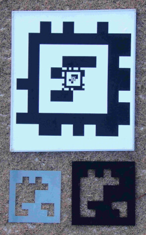
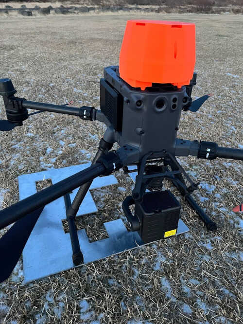
We conduct real-world landing experiments to test the accuracy of the method. We use 3 different landing pads, as shown in Fig. 3. To test the method’s basic and long-range performance, we use a visual landing pad with 3 concentric April Tag markers. The smaller markers allow the system to detect the landing pad at low altitudes. We test two IR landing pads for nighttime landing, both in the shape of an April Tag 36h11 with ID 564 because its lack of islands and thin corners allow it to be reliably cut out of a single, contiguous piece of metal. The actively-heated IR landing pad (right) is made out of steel with vinyl tape on the top to increase its emissivity. It emits relatively high IR radiation compared to the ground because of its actual temperature difference [28]. Since it emits IR radiation in the dark regions of the corresponding April Tag marker, we invert the IR stream before passing it to the April Tag detector. Heating the landing pad is an intuitive way of increasing its IR radiation but requires a power source. For this reason, we also test a passive aluminum IR landing pad (left), which is at ambient temperature when in use and requires no power source. Its high reflectivity means that it reflects the IR radiation from the sky, which is relatively low compared to the ground, and thus the landing pad appears cold and dark. The differences in the sizes of the landing pads are due only to incidental availability of materials. We test on a DJI Matrice 350 [29] with an H20T [30], which has wide-angle, zoom, and IR cameras. We implement the control policy on a custom computational payload (see Fig. 4) containing a Raspberry Pi 4 that is mounted onboard the drone and runs a DJI Payload SDK application to handle video decoding, data subscription, camera management, gimbal control, flight control, and widgets for interaction with the pilot [31].
IV Results
We conducted 26 tests over 4 days with air temperatures ranging from C to C, wind conditions less than 5 m/s, on a grassy field in Iceland with light snow. We started each test by manually positioning the drone at a horizontal distance between 5m and 168m from the landing pad, and altitude of 5m to 102m above the landing pad. We then gave control of the drone to the computational payload, which directed the landing according to the policy in Fig. 2, while we simply monitored its behavior. The error of the landing is measured as the distance from the center of the landing pad to the point directly under the drone’s camera after touchdown. Sample landing videos can be found on Vimeo [32].
| Type | (m) | (m) | Max Alt (m) | Max Dist (m) | |
|---|---|---|---|---|---|
| Visual | 0.16 | 0.10 | 11 | 102 | 168 |
| Active IR | 0.14 | 0.14 | 5 | 15 | 15 |
| Passive IR | 0.26 | 0.17 | 10 | 15 | 14 |
| All | 0.19 | 0.14 | 26 | 102 | 168 |
Table II shows the distribution of the landing error, where is the average error, is the standard deviation of the error, is the number of tests per type, and Max Alt. and Max Dist. are the maximum starting altitudes and horizontal distances for the landing tests. All tests were successful, i.e., the drone landed at least touching the landing pad, with an average error of 0.19m, which is lower than most of the previous work – except those using sophisticated systems e.g., RTK and LiDAR– and does not depend on the commonly-needed AGL or range from Fig. 1. This demonstrates the viability of the method and each of the landing pad types.
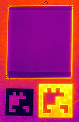
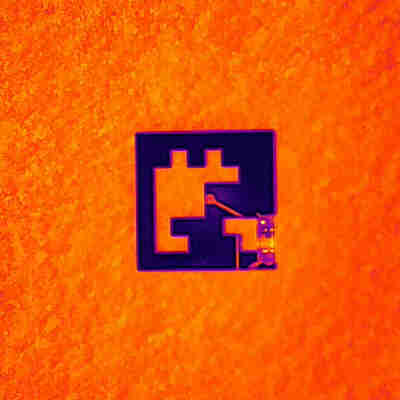
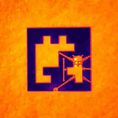
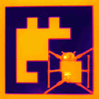
The system carries out landings from much longer distances than previously reported using the visual landing pad and zoom camera. The IR camera’s range is limited by its lack of zoom, but these experiments demonstrate the viability of using both active and passive IR fiducial markers for autonomous landing. The active IR landing pad provides consistent performance and is clearly recognizable. The passive IR landing pad requires no power source but reflects the drone’s IR radiation (see Fig. 5), causing occlusion when horizontally aligned at low altitudes and necessitating the commit state. The performance of the passive IR landing pad may be weather-dependent and requires further testing. Since the the control policy is the same for all landing pads, the only major performance difference is the maximum detection distance.
IV-A Case Study: Antagonistic Landing Site
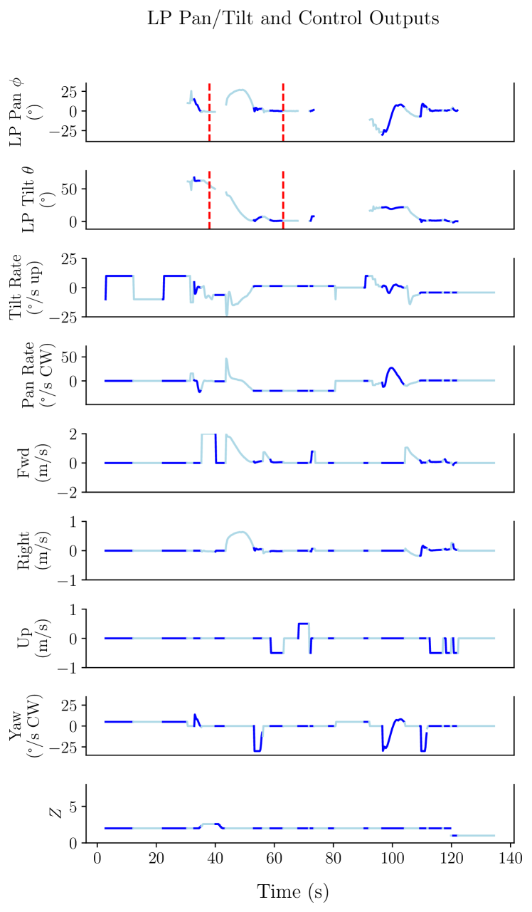
Successes in the first experiment led to a more antagonistic second experiment where the landing pad was intentionally obscured both during the approach and descent states to test the system’s ability to recover from detection loss. Fig. 6 illustrates this, showing the control signals for a landing with the visual landing pad and the zoom camera. The system reacquires the landing pad each time by zooming out or ascending to increase its field of view, restarts the search process entirely when necessary, and ultimately lands successfully. The drone starts at a distance of 20m and altitude of 10m relative to the landing pad. It searches for the landing pad by tilting the gimbal up and down while yawing clockwise from the start until . Then, it detects the landing pad, aiming the camera at it until and aiming the drone at it until . It begins its approach until the landing pad is intentionally obscured and thrown to the side at , at which point it zooms out and finds the landing pad towards its right. It begins its approach again at , until arriving above it at , when it turns counterclockwise to align with the landing pad’s yaw. It conducts a horizontal alignment at and begins its descent at . At , the landing pad is again intentionally obscured and thrown to the side, causing the drone to enter the zoom out 2 state At , it begins its ascent and momentarily re-acquires the marker at . It zooms out and begins the search process again at , first with static search until , then search down until , and search up until , at which point it re-acquires the marker. It aims the camera again until , then approaches until , then aligns to the landing pad’s yaw until . It alternates between horizontal alignment and descent 3 times until , when it is gradually getting closer to the landing pad in the horizontal and vertical dimensions, and during this time it switches to the wide-angle stream with . Finally, it commits to the landing and descends vertically until it touches down on the landing pad and disables the motors at . This demonstrates that the system is able to recover from detection losses by zooming out, ascending, or restarting the search process.
V Conclusions & Future Work
We have presented a method of autonomous precision drone landing that can use either visual or IR fiducial markers and achieves an average error of 0.19m. It has fewer data requirements than previous work, i.e., the direction towards the landing pad, the landing pad’s pixel size, and the camera’s zoom factor; it does not use the drone’s height or distance relative to the landing pad. It avoids 6 DoF fiducial pose estimation, eliminating the orientation ambiguity problem from our previous study [23]. The method is successful from much longer distances than previous work, with a zoom camera and visual fiducial markers. It works at both daytime and nighttime using actively-heated and passive (unpowered), high-reflectivity IR fiducial markers. Finally, the control policy enables the drone to search for the landing pad and reacquire it if it is lost, making the landings more reliable.
Further testing of this method includes testing different marker systems, weather conditions, and background surfaces. Using a PID system (instead of a simple P system) to calculate velocity targets would allow the method to generalize to moving landing pads.
References
- [1] H. Kim, C.-U. Hyun, H.-D. Park, and J. Cha, “Image Mapping Accuracy Evaluation Using UAV with Standalone, Differential (RTK), and PPP GNSS Positioning Techniques in an Abandoned Mine Site,” Sensors, vol. 23, no. 13, 2023. [Online]. Available: https://www.mdpi.com/1424-8220/23/13/5858
- [2] M. Krogius, A. Haggenmiller, and E. Olson, “Flexible Layouts for Fiducial Tags,” in 2019 IEEE/RSJ International Conference on Intelligent Robots and Systems (IROS). IEEE Press, 2019, p. 1898–1903. [Online]. Available: https://doi.org/10.1109/IROS40897.2019.8967787
- [3] M. Fiala, “ARTag, a fiducial marker system using digital techniques,” 2005 IEEE Computer Society Conference on Computer Vision and Pattern Recognition (CVPR’05), vol. 2, pp. 590–596 vol. 2, 2005. [Online]. Available: https://api.semanticscholar.org/CorpusID:5746274
- [4] S. Garrido-Jurado, R. Muñoz-Salinas, F. Madrid-Cuevas, and M. Marín-Jiménez, “Automatic generation and detection of highly reliable fiducial markers under occlusion,” Pattern Recognition, vol. 47, no. 6, pp. 2280–2292, 2014. [Online]. Available: https://www.sciencedirect.com/science/article/pii/S0031320314000235
- [5] P. Lightbody, T. Krajník, and M. Hanheide, “A versatile high-performance visual fiducial marker detection system with scalable identity encoding,” Proceedings of the Symposium on Applied Computing, 2017. [Online]. Available: https://api.semanticscholar.org/CorpusID:5013993
- [6] G. Schweighofer and A. Pinz, “Robust Pose Estimation from a Planar Target,” IEEE Transactions on Pattern Analysis and Machine Intelligence, vol. 28, no. 12, pp. 2024–2030, 2006.
- [7] J. Springer and M. Kyas, “Evaluation of Orientation Ambiguity and Detection Rate in April Tag and WhyCode,” in 2022 Sixth IEEE International Conference on Robotic Computing (IRC). Naples, Italy: IEEE Computer Society, Dec 2022, pp. 281–286. [Online]. Available: https://doi.ieeecomputersociety.org/10.1109/IRC55401.2022.00054
- [8] O. Araar, N. Aouf, and I. Vitanov, “Vision based autonomous landing of multirotor uav on moving platform,” Journal of Intelligent & Robotic Systems, vol. 85, pp. 369–384, 2016.
- [9] M. A. Olivares-Mendez, I. F. Mondragón, and P. Campoy, “Autonomous Landing of an Unmanned Aerial Vehicle using Image-Based Fuzzy Control,” IFAC Proceedings Volumes, vol. 46, no. 30, pp. 79–86, 2013, 2nd IFAC Workshop on Research, Education and Development of Unmanned Aerial Systems. [Online]. Available: https://www.sciencedirect.com/science/article/pii/S1474667015402757
- [10] G. Badakis, M. Koutsoubelias, and S. Lalis, “Robust Precision Landing for Autonomous Drones Combining Vision-based and Infrared Sensors,” in 2021 IEEE Sensors Applications Symposium (SAS), 2021, pp. 1–6.
- [11] E. Nowak, K. Gupta, and H. Najjaran, “Development of a Plug-and-Play Infrared Landing System for Multirotor Unmanned Aerial Vehicles,” in 2017 14th Conference on Computer and Robot Vision (CRV), 2017, pp. 256–260.
- [12] N. Xuan-Mung, S. K. Hong, N. P. Nguyen, L. N. N. T. Ha, and T.-L. Le, “Autonomous Quadcopter Precision Landing Onto a Heaving Platform: New Method and Experiment,” IEEE Access, vol. 8, pp. 167 192–167 202, 2020.
- [13] K. Pluckter and S. Scherer, “Precision UAV Landing in Unstructured Environments,” in Proceedings of the 2018 International Symposium on Experimental Robotics, ser. Springer Proceedings in Advanced Robotics, J. Xiao, T. Kröger, and O. Khatib, Eds., vol. 11. Cham: Springer, 2018, pp. 177––187.
- [14] R. Polvara, S. Sharma, J. Wan, A. Manning, and R. Sutton, “Towards autonomous landing on a moving vessel through fiducial markers,” in 2017 European Conference on Mobile Robots (ECMR), 2017, pp. 1–6.
- [15] D. Falanga, A. Zanchettin, A. Simovic, J. Delmerico, and D. Scaramuzza, “Vision-based autonomous quadrotor landing on a moving platform,” in 2017 IEEE International Symposium on Safety, Security and Rescue Robotics (SSRR), 2017, pp. 200–207.
- [16] A. Borowczyk, D.-T. Nguyen, A. Phu-Van Nguyen, D. Q. Nguyen, D. Saussié, and J. L. Ny, “Autonomous Landing of a Multirotor Micro Air Vehicle on a High Velocity Ground Vehicle**This work was partially supported by CFI JELF Award 32848 and a hardware donation from DJI.” IFAC-PapersOnLine, vol. 50, no. 1, pp. 10 488–10 494, 2017, 20th IFAC World Congress. [Online]. Available: https://www.sciencedirect.com/science/article/pii/S2405896317326186
- [17] G. Cho, J. Choi, G. Bae, and H. Oh, “Autonomous ship deck landing of a quadrotor UAV using feed-forward image-based visual servoing,” Aerospace Science and Technology, vol. 130, p. 107869, 2022. [Online]. Available: https://www.sciencedirect.com/science/article/pii/S1270963822005430
- [18] T. Jiang, D. Lin, and T. Song, “Vision-based autonomous landing of a quadrotor using a gimbaled camera,” Proceedings of the Institution of Mechanical Engineers, Part G: Journal of Aerospace Engineering, vol. 233, no. 14, pp. 5093–5106, 2019. [Online]. Available: https://doi.org/10.1177/0954410019837777
- [19] M. Demirhan and C. Premachandra, “Development of an Automated Camera-Based Drone Landing System,” IEEE Access, vol. 8, pp. 202 111–202 121, 2020.
- [20] J. Lim, T. Lee, S. Pyo, J. Lee, J. Kim, and J. Lee, “Hemispherical InfraRed (IR) Marker for Reliable Detection for Autonomous Landing on a Moving Ground Vehicle From Various Altitude Angles,” IEEE/ASME Transactions on Mechatronics, vol. 27, no. 1, pp. 485–492, 2022.
- [21] H. Tanaka, K. Ogata, and Y. Matsumoto, “Solving pose ambiguity of planar visual marker by wavelike two-tone patterns,” 2017 IEEE/RSJ International Conference on Intelligent Robots and Systems (IROS), pp. 568–573, 2017. [Online]. Available: https://api.semanticscholar.org/CorpusID:30231919
- [22] H. Tanaka and Y. Matsumoto, “Autonomous Drone Guidance and Landing System Using AR/high-accuracy Hybrid Markers,” in 2019 IEEE 8th Global Conference on Consumer Electronics (GCCE), 2019, pp. 598–599.
- [23] J. Springer and M. Kyas, “Autonomous Drone Landing with Fiducial Markers and a Gimbal-Mounted Camera for Active Tracking,” in 2022 Sixth IEEE International Conference on Robotic Computing (IRC). Naples, Italy: IEEE Computer Society, Dec 2022, pp. 243–247. [Online]. Available: https://doi.ieeecomputersociety.org/10.1109/IRC55401.2022.00047
- [24] M. D. Dogan, A. Taka, M. Lu, Y. Zhu, A. Kumar, A. Gupta, and S. Mueller, “InfraredTags: Embedding Invisible AR Markers and Barcodes Using Low-Cost, Infrared-Based 3D Printing and Imaging Tools,” in Proceedings of the 2022 CHI Conference on Human Factors in Computing Systems, ser. CHI ’22. New York, NY, USA: Association for Computing Machinery, 2022. [Online]. Available: https://doi.org/10.1145/3491102.3501951
- [25] S. Khattak, C. Papachristos, and K. Alexis, “Marker Based Thermal-Inertial Localization for Aerial Robots in Obscurant Filled Environments,” 11 2018, pp. 565–575.
- [26] R. M. Claro, D. B. Silva, and A. M. Pinto, “ArTuga: A novel multimodal fiducial marker for aerial robotics,” Robotics and Autonomous Systems, vol. 163, p. 104398, 2023. [Online]. Available: https://www.sciencedirect.com/science/article/pii/S0921889023000374
- [27] A. Rowlands, Physics of Digital Photography, ser. 2053-2563. IOP Publishing, 2017. [Online]. Available: https://dx.doi.org/10.1088/978-0-7503-1242-4
- [28] Z. M. Zhang and G. Machin, “Chapter 1 Overview of Radiation Thermometry,” in Radiometric Temperature Measurements: I. Fundamentals, ser. Experimental Methods in the Physical Sciences, Z. M. Zhang, B. K. Tsai, and G. Machin, Eds. Academic Press, 2009, vol. 42, pp. 22–23,107. [Online]. Available: https://www.sciencedirect.com/science/article/pii/S1079404209042015
- [29] Matrice 350 RTK User Manual. Da Jiang Innovations (DJI), 2023. [Online]. Available: https://dl.djicdn.com/downloads/matrice_350_rtk/Matrice_350_RTK_User_Manual_en.pdf
- [30] Zenmuse H20 Series User Manual. Da Jiang Innovations (DJI), May 2020. [Online]. Available: {https://dl.djicdn.com/downloads/Zenmuse_H20_Series/Zenmuse_H20_Series_User_Manual-EN.pdf}
- [31] J. Springer, “Payload-SDK App: RPi Autonomous Landing,” https://github.com/uzgit/Payload-SDK/tree/apriltag, 2023.
- [32] Matrice Fiducial Landings Demo. Vimeo, March 2024. [Online]. Available: {https://vimeo.com/j0shua/matrice-fiducial-demo-visir}