Designing Library of Skill-Agents for Hardware-Level Reusability
Abstract
To use new robot hardware in a new environment, it is necessary to develop a control program tailored to the specific robot in the environment. Considering the reusability of software among robots is crucial to minimize the effort involved in this process and maximize software reuse across different robots in different environments. Although recent generative AI has made it possible to automatically generate some software, robot programs are still difficult to generate because of robot’s physical interaction with the environment. This paper proposes a method to remedy this process by considering hardware-level reusability, using a Learning-from-observation (LfO) framework with a pre-designed skill-agent library. The LfO framework represents the required actions in hardware-independent representations, referred to as task models, from observing human demonstrations, capturing the necessary parameters for the interaction between the environment and the robot (Ikeuchi et al. (2021)). When executing the desired actions from the task models, a set of skill agents is employed to convert the representations into robot commands. This paper focuses on the latter part of the LfO framework, utilizing the skill-agent set to generate robot actions from the task models, and explores a hardware-independent design approach for these skill agents. These skill agents are described in a hardware-independent manner, considering the relative relationship between the robot’s hand position and the environment. As a result, it is possible to execute these actions on robots with different hardware configurations by simply swapping the inverse kinematics solver. This paper, first, defines a necessary and sufficient skill-agent set corresponding to cover all possible actions, and considers the design principles for these skill agents. We provide concrete examples of such skill agents and demonstrate the practicality of these skill agents by showing that the same representations can be executed on two different robots, Nextage and Fetch, using the proposed skill-agent set.
1 Introduction
Robot developers develop various types of robots, such as bipedal robots and mobile manipulators for satisfying users’ various demands. If we consider manipulation aspects, there are various types: a single-arm robot or a dual-arm robot, and the degrees of freedom (DOF) of an arm is from 5 (e.g., HSR, Toyota) to 7 (e.g., Fetch Mobile Manipulator, Fetch Robotics). Some robots have additional DOF on their waist.
Users’ demands are related to their backgrounds and robots suitable for users may vary. If a certain developer would adopt a new robot from the previously used one, robot-specific software has to be changed. On the other hand, robot-software developers would like to reuse their developed software as much as possible to reduce their efforts. It is desirable to satisfy those two conflicting demands.
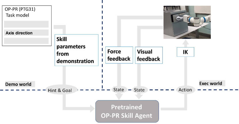
We have been developing a robot system based on a Learning-from-Observation (LfO) framework (Ikeuchi et al. (2021))111In the machine-learning (ML) community, Learning-from-Observation (LfO) is used with a slightly different definition. However, following the rationale mentioned in the introduction of Ikeuchi et al. (2021), LfO is specifically referred to as a method that transforms input into symbolic representations based on top-down knowledge and subsequently maps them to robot actions.. Our goal is to have a robot reproduce the target behavior by simply demonstrating it in front of the robot. Thus, even users without robotics knowledge can have the robot perform tasks that they desire. Unlike similar frameworks, such as learning-from-demonstration and imitation learning (Schaal (1999); Schaal et al. (2003); Billard et al. (2008); Asfour et al. (2008); Dillmann et al. (2010); Akgun et al. (2012)), the LfO system preforms indirect behavior mimicry by first a task-encoding step converting the demonstration into an abstract intermediate representation, referred to as a task model, and then a task-decoding step converting this intermediate representation into the behavior of each robot. The task-encoding recognizes behavior as symbolic task sequences (such as a sequence of pick up, place, and release actions) and then extracts from the demonstration the parameters that are pre-defined in each task (such as where to grasp and where to put). Because only task-specific information is extracted from the demonstration, unnecessary parts are ignored, allowing the demonstrator to focus only on the important demonstration parts that need to be taught. For task-decoding, we prepare in advance the skill agents, which correspond to the agents performing symbolic actions, following the design of the task model. Then, the reproduction by a robot is realized by activating the corresponding skill agent with the observed parameters.
This paper focuses on the second step of the LfO, to build the robot-independent task-decoder from task models to actions. For task-decoding, hardware-independent skill agents corresponding to each task are pre-designed and stored in the library. These skill agents represent the tasks only by hand motions to absorb the structural difference between each robot, and the robot arm and body is regarded as a carrier used to move the hand on the desired trajectory. Given a target trajectory by a skill agent, a general inverse kinematics (IK) solver, body role division (Sasabuchi et al. (2021)), is used to determine the robot’s body motion to achieve this trajectory.
The contribution of this paper is threefold:
-
•
definition of a robot-independent, necessary and sufficient skill-agent set for manipulation tasks involving force/visual feedback
-
•
proposal for design principles of skill agents and implementation examples of a skill-agent set using the principles
-
•
demonstration of a reusable system using the skill-agent set
2 Related work
Efforts to increase reusability of robot programs, such as Robot Operating System (ROS) (Quigley (2009)) and OpenRTM (Ando et al. (2008)), have been conducted thus far. These two pieces of middleware follow a so-called subsumption architecture (Brooks (1986)). In this architecture, a robot program are created by combining several nodes. The nodes are properly connected and communicate with each other to execute the program. These two pieces of middleware achieved reusability by 1) unifying the format of communication and 2) providing means of communication (e.g., publisher and subscriber in ROS). Switching between low-level nodes (e.g., nodes to output sensor reading) is very easy.
In high-level nodes, it is necessary to take into account the individual characteristics of the robot hardware. For example, to move a mobile robot on a floor, we can define a de-facto standard robot command (e.g., a pair of velocity and angular velocity) and combinations of nodes (the occupancy grid map (Moravec and Elfes (1985)) and Monte Carlo localization (Dellaert et al. (1999))). These two pieces of middleware provide open-source nodes for various robots. Conversely, if we could define the robot-independent action representation, hardware-level reusability can be increased by converting that representation into a robot-specific control signal. Bachiller-Burgos et al. (2020) proposed the STEM education programming tool where the robot hardware can be changed without modifying programs created by students. In the hardware-level reusablity, the robot-independent representation and their conversion play important roles.
In manipulation aspects, which are our main targets, the control strategy of the manipulator differs from situations, such as simple position control, impedance control (Hogan (1984)), and machine-learning-based control (Jin et al. (2018)). But to realize manipulation at a minimum, the end-effector must be brought to the desired position. To bring to the desired position, it is necessary to decide on the robot joints to satisfy the target end-effector position. IK solver is a one of the solution and many proposals and implementations for IK are available, such as Beeson and Ames (2015); Starke et al. (2017). Cheng et al. (2018) developed the globally stable controller within non-Euclidean spaces. They succeeded in the reactive motion generation (e.g., avoid obstacles) in real-time. The proposed skill agents output the target configuration of the end-effector and any methods to generate motions from the output are acceptable. In the sense of the hardware-level reusability, Murali et al. (2019) proposed the open-source robotics framework that provides hardware independent mid-level APIs including FK/IK, robot vision, and planning for low-code development. By further considering task models and task decoders, this paper aims to provide a hardware-unaware robot programming environment.
Recently, several papers showed the importance on the awareness of action primitives, which correspond to tasks/skills in the proposed system, in the learning-from-demonstration framework. Lin et al. (2022) succeeded in the complicated tasks with multiple action primitives by training each primitive independently and combining them with sub-goals. Edmonds et al. (2019) succeeded to open medicine bottles with different locking mechanisms by learning discrete haptic states and grammatical representation of action primitives. The proposed system will prove that the goal oriented action primitives contribute to the hardware-level reusability, too.
3 Designing re-usable skill-agent library
3.1 Overview
This section aims to design the skill-agent library that enables hardware-level reuse. We assume that the task sequence starts with grasping a target object, continues by manipulating it, and ends to release it. Within this paper, we primarily focus on manipulation skill agents, assuming the grasping skill agents can be addressed through a separate methodology presented in Saito et al. (2022). Therefore, we assume that the manipulated object is already grasped, and the object and hand are integrated. Assuming a robot with redundant DOF and a situation where hand motions and arm motions can be independently resolved through the body role division (Sasabuchi et al. (2021)), we focus solely on hand motions when designing each skill agent.
In this paper, two terms, task and skill, are frequently used. A task is defined as a unit operation of what-to-do, obtained in the encoding part of LfO and on the decoding side, the procedure for a robot to perform this is referred to as a skill and the skill agent are responsible for the execution of a skill. Tasks and skills correspond one-to-one under an assumption of usage of one particular robot hardware, and in this paper, unless otherwise specified, they are used interchangeably without confusion. This paper aims to remove this constraint, i.e., differences of skills among robots, and to design skill agents that can be reused among a wide range of robot hardware. In each skill agent, the object displacement due to the hand motion is calculated to satisfy constraints from the environment. The displacement in unconstrained subspace is assumed to be obtained from the demonstration. The parameters required to perform these skills are called skill parameters.
In this paper, we assume that the environment between in demonstration and in robot execution is not dramatically changed. The demonstration includes a hint for collision avoidance and a robot can execute the target task by following the demonstration. Of course, we admit a slight difference in the environment in robot execution; the skill agent can absorb the difference using sensor feedback.
The grasped object is in contact with the environment. A single operation of the robot, consisting of translational and rotational motions, induces contact-state transitions between the object’s surface and the environment. In a previous paper (Ikeuchi et al. (2021)), we defined the necessary and sufficient set of tasks that should be prepared as robot manipulations based on translational and rotational transitions. In this paper, we design skill agents to execute these defined tasks, assuming force feedback and visual feedback. During the design of each skill agent, we utilize changes in forces from the environment and/or visual features of the environment according to surface contact transitions and derive reward functions that ensure successful transitions using them. These skill agents are pre-trained through reinforcement learning based on these reward functions.
Traditionally, reinforcement learning (RL) has been employed to adjust the trajectory of a robot’s hand, taking into account drag forces from the environment. Previous RL methods have predominantly focused on the design of reward functions for specific operations and requiring individual learning for each new operation coming. We propose grouping multiple operations based on the types of physical constraints, deriving general guidelines, and proposing reward functions applicable to various operations based on these guidelines.
In the following discussion, to maintain continuity with the previous paper, we will first revisit the necessary concepts. Subsequently, we will outline the design principles and then proceed to the design of each skill agent.
3.2 Preliminary
3.2.1 Surface contact and contact transition
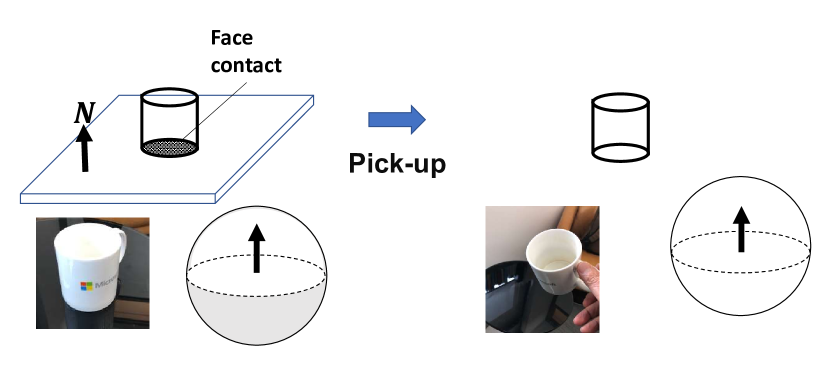
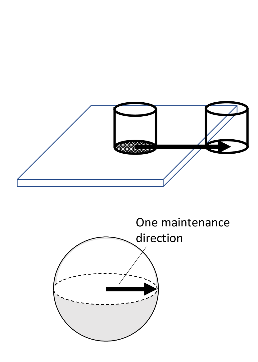
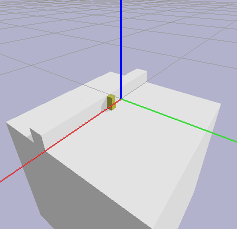
The grasped object and the environment come into contact at the object’s surface and environmental constraint points, resulting in restriction of possible motion directions of the object. One unit of manipulation actions, i.e., one task in our terminology, can be defined as one that causes one transition in the motion constraint state of the object grasped. For example, when picking up an object on a table, in the initial state, the possible directions of motion for the object are limited to above the table surface. Representing the possible motion directions on the Gaussian sphere, with the normal direction of the table surface as the North Pole, the Northern hemisphere, depicted as a white region in the left sphere in Figure 1, represents the possible motion directions. After picking up, there are no constraints from the environment, and the motion is possible in all directions, corresponding to the entire surface of the Gaussian sphere in the right side of Figure 1. The pick-up task can be defined as one to cause the transition of the motion constraint state of the object from a Hemispherical-constraint state to a No-constraint state.
The constraints on the translational and rotational motion of an object, given by a contact point , can be expressed using the screw theory (Roth (1984)):
| (1) |
where denotes the normal vector at the contact point and denotes the screw axis vector. A translational motion occurs along , and a rotational motion occurs around . When the ratio between the translation and rotation is defined by the parameter , , where is the center of rotation. Namely, one pair of an object surface and an environment contact point provides one linear inequality for the constraints on object motion. In this paper, following the approach of the previous paper, we assume that robot manipulation involves only pure translation or pure rotation. We do not consider compound operations involving both. In the following, we will divide the analysis into translational or rotational motion, with the main analysis being translation.
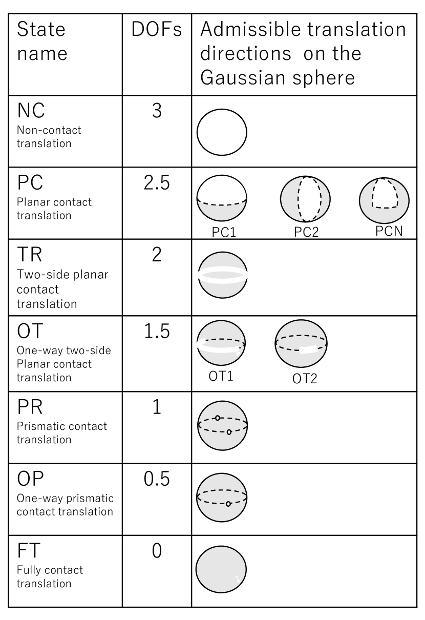
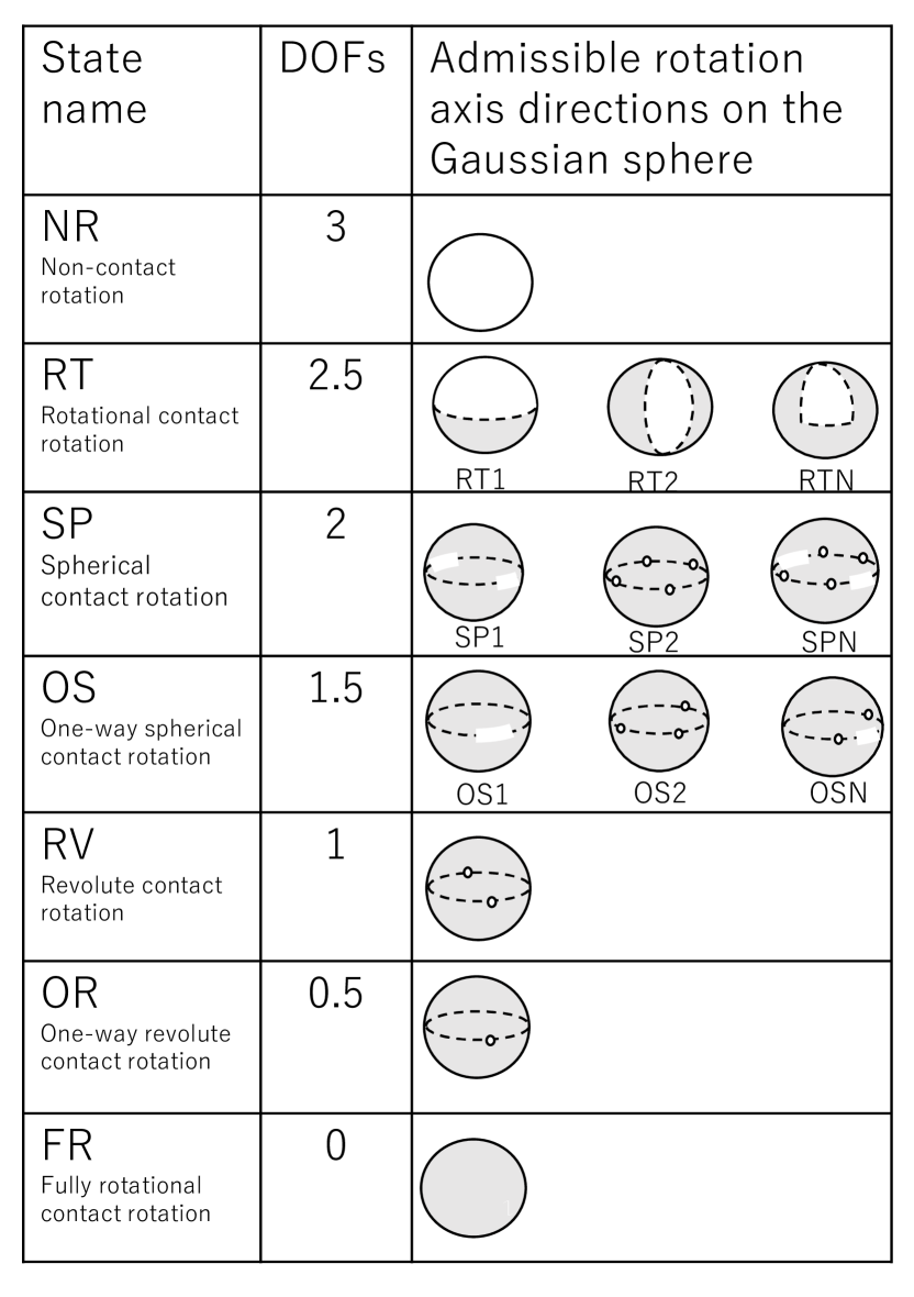
When multiple contact pairs exist, the solution space of these simultaneous inequalities given by them become the possible directions of the object’s motion. Using the Kuhn-Tucker theory (Kuhn and Tucker (1957)), the solution space of these simultaneous inequalities can be classified into 10 classes. For the sake of analysis simplification, these 10 classes of solution spaces are further grouped into 7 types based on the dimension of the DOF, as illustrated in Figure 2. Note that PC1, PC2, and PCN were treated as the same PC state, and OT1 and OT2 were also processed as the same OT state. We use this classification as the states of an object.
|
|
|---|---|
| (a) | (b) |
3.2.2 Maintenance, detachment, and constraint dimensions
The relative DOF of an object with respect to the environment can be categorized into three translational and three rotational dimensions. These three dimensions are, further, classified into three types: maintenance dimension, detachment dimension, and constraint dimension.
-
Maintenance dimension: The maintenance dimension is a dimension in which small transnational or rotational motion do not face any constraints. For example, when an object is floating in the air, the object can move in any direction within these three dimensions without experiencing any resistance from the environment. Dimensions with such full degrees of freedom are referred to as maintenance dimensions.
-
Detachment dimension: The detachment dimension is a dimension where small translational or rotational motions in that dimension result in the loss of contact. In the opposite direction, any translational or rotational motions are constrained by drag from the environment. For example, a cup on a tabletop can move away from the table, breaking the contact between the surfaces. However, it cannot move towards the table due to the drag. Dimensions with these half degrees of freedom are defined as detachment dimensions.
-
Constraint dimension: The constraint dimension is a dimension where motions are constrained by resistance from the environment. For example, a drawer is constrained from moving in the direction of its side due to the resistance from the surrounding walls. Dimensions lacking such degrees of freedom are termed constraint dimensions.
For states defined by translational motion, maintenance DOF, detachment DOF, and constraint DOF are assigned as shown on the left side of Table 1. Since there are three DOF for translation, the total sum of the numbers is 3. Similarly, dimensions can be defined for rotational states as shown on the right side of the table.
| Translation | Rotation | ||||||
| State | Maintenance | Detachment | Constraint | State | Maintenance | Detachment | Constraint |
| NC | 3 | 0 | 0 | NR | 3 | 0 | 0 |
| PC1 | 2 | 1 | 0 | RT1 | 2 | 1 | 0 |
| TR | 2 | 0 | 1 | SP | 2 | 0 | 1 |
| PC2 | 1 | 2 | 0 | RT2 | 1 | 2 | 0 |
| OT1 | 1 | 1 | 1 | OS1 | 1 | 1 | 1 |
| PR | 1 | 0 | 2 | RV | 1 | 0 | 2 |
| PCN | 0 | 3 | 0 | RTN | 0 | 3 | 0 |
| OT2 | 0 | 2 | 1 | OS2 | 0 | 2 | 1 |
| OP | 0 | 1 | 2 | OR | 0 | 1 | 2 |
| FT | 0 | 0 | 3 | FR | 0 | 0 | 3 |
3.2.3 State transitions and skill agents
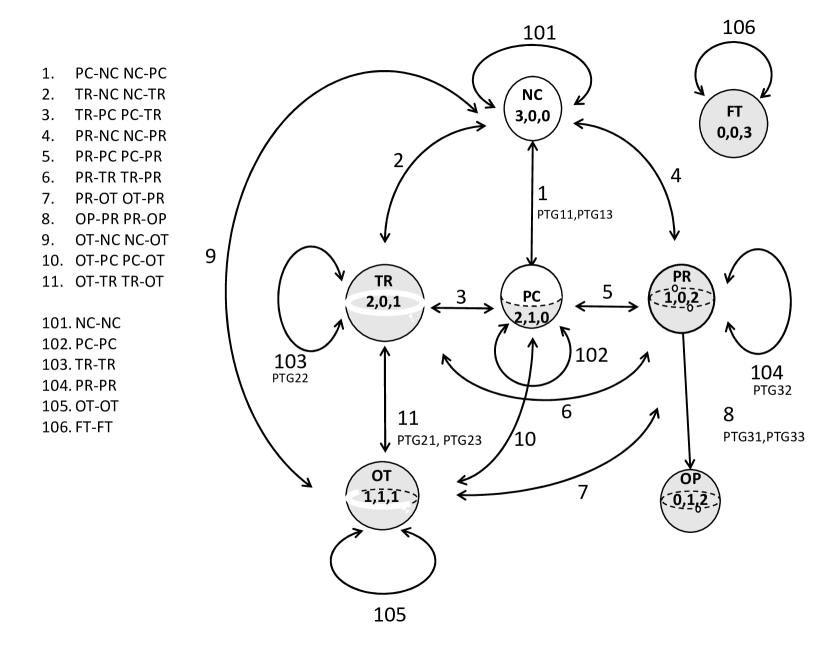
Tasks are defined as transitions between these states. The transition of states are shown in Figure 3. In other words, these branches in the graph are defined as tasks, and the purpose of this paper is to design the skill agents to perform these tasks.
(a) Translational tasks
(b) Rotational tasks
3.3 Design principles for translational skill-agents
This subsection presents the design principles that are applied to all skill agents, and the next subsection applies these principles to all skill agents to design the reward functions for learning them. Although some of the skill agents may not be practical for robot execution, we design all the reward functions by applying the design principles to all the skill agents regardless of their practicality in order to informally prove the correctness of the design principles as well as to show the upper bound of the skill-agent set.
We will design the reward functions based on the dimensional transitions. Although transitions themselves occur through infinitesimal translation or rotation, we design skill agents by assuming actual skills performed by a robot, that is, the current state persists for an finite (not infinitesimal) interval before a transition, then, the state transition occurs, and finally a new state persists for another finite interval.
When designing the reward functions for translational skills, we will provide separate principles for the transition along the direction of motion and those orthogonal to the motion. This is because the transition along the direction of motion mainly affects the termination conditions of the skill agent, while directions orthogonal to the motion are related to motion control strategies during motion. We will first provide principles for the direction of motion and then consider principles for directions orthogonal to the motion.
3.3.1 Transition along the motion
The limitation on the direction of motion depends on which dimension the direction of motion belongs to. If it is in the maintenance dimension, the object can move in both directions. If it is in the detachment dimension, it can only move in one direction. If it is in the constraint dimension, the object cannot move in that direction. Thus, for state transitions in the motion direction, three cases occur: from the maintenance dimension to the maintenance dimension, from the maintenance dimension to the detachment dimension, and from the detachment dimension to the maintenance dimension: A1, A2 and A3. See Figure 4.
Note that we denote the coordinate aligned with the direction of motion as S, the drag force of the opposing motion direction as F-s and the drag force along the motion direction as F+s. The two orthogonal directions to the motion direction and the drag forces in these directions are denoted as T, U, F-t, F-u, respectively. Also, let us denote the threshold for determining whether a collision has occurred or not based on the drag force as delta-collision, and the threshold for determining whether the contact has been lost or not as delta-zero. We also note the threshold for determining whether the position of visual features matches or not as delta-gap.
In the following discussion, we define one direction belonging to a certain dimension as a directional state. For example, when one direction is in the maintenance dimension, we call that the direction is the maintenance directional state (d-state). This d-state is defined to distinguish it from the state of the entire object. As long as there is no confusion, dimensions and d-states are used interchangeably.
A1: maintenance to maintenance
When the maintenance d-state is maintained along the motion direction, no drag force occurs at the end of the motion as well as during the motion. Therefore, the skill agent can be defined solely based on positional information (i.e., reach to the goal position in the S coordinate) given by the demonstration.
if S = goal-s, then reward
The term goal-s is the goal position in the S coordinate.
A2: maintenance to detachment
Drag force that was absent in a maintenance d-state arises upon contact with an environment surface, occurring at the point of transitioning to the detachment d-state. Therefore, the occurrence of this drag force serves as the termination condition for this skill. Under normal circumstances with no errors, the contact position should align with the position given by the demonstration. However, for the sake of operational robustness to allow more gaps between the demonstration and the execution, the occurrence of the drag force from the environment is considered as the termination condition for the skill agent.
if F-s > delta-zero, then reward
A3: detachment to maintenance
By moving in a admissible semi-direction in the detachment dimension, the object moves away from the environment contact surface, leading to the transition from the detachment d-state to the maintenance d-state. The disappearance of the drag force that exists in the detachment d-state can be considered as the termination condition for the skill. However, given the existence of motion in the maintenance d-state within a finite interval, the disappearance of the drag force and the the achievement of goal position are considered as the terminal conditions for this skill agent.
    if F+s < delta-zero AND S = goal-s,
      then reward
3.3.2 Transition in the dimension orthogonal to the motion
When considering transitions in the dimension orthogonal to the motion direction, nine cases can occur. See Figure 5. In the following, the dimension considered is denoted as T, and the drag force encountered from the environment along this direction is represented as F-t.
B1: maintenance to maintenance
A moving object to have a maintenance d-state in the orthogonal direction to the motion is not constrained by the environment in that direction. Therefore, the position error in that direction can be tolerated and the end position of the skill in this direction is solely determined by the demonstration.
if T = goal-t, then reward
The term goal-t is the goal position in the T coordinate.
B2: detachment to detachment
Maintaining the detachment d-state in an orthogonal direction to the motion is equivalent to maintaining surface contact in the orthogonal direction during the motion. Therefore, throughout the motion, it is necessary to keep the drag force from the environment within a certain range. In other words, the adjustment of the moving direction is required to ensure that the drag force does not become too large, leading to collision, and also to prevent it from reaching zero, resulting in separation from the surface.
    if F-t > delta-collision, then penalty
    if F-t < delta-zero, then penalty
B3: constraint to constraint
To maintain the constraint d-state in the orthogonal direction, similar to B2, it is necessary to adjust the motion direction to minimize the drag force in the orthogonal direction. However, there is no detachment from the constraint d-state in the orthogonal direction, so the second condition corresponding to the delta-zero condition in the case of B2 is not necessary.
if F-t > delta-collision, then penalty
B4: maintenance to detachment
For the transition, it is necessary to adjust the motion direction to achieve surface contact in the detachment d-state. Since there is no surface contact in the orthogonal direction in the maintenance d-state, the adjustment needs to be done using positional information from visual sensors. Let us denote the position of the contact surface in the orthogonal direction as feature-t. For example, adjusting the position in the T coordinate of the manipulating object to the boundary edge of the surface that will be in contact gives an advantage in accomplishing the task. The skill agent aligns the positional information in the orthogonal direction using this value.
After the transition, the motion direction is adjusted to maintain the detachment d-state in the same as in the B2 case. In order to specify whether the transition occurs or not, we introduce a flag referred to AfterTransition.
  if NOT(AfterTransition):
    if |T - feature-t| > delta-gap,
      then penalty
  else:
    if F-t > delta-collision, then penalty
    if F-t < delta-zero, then penalty
B5: detachment to maintenance
In the finite interval before the transition, the motion direction is adjusted to maintain the surface contact in the orthogonal direction, i.e., detachment d-state in this direction. For this, the drag force F-t should be no greater than delta-collision so that the object dips into the environmental surface. In strict sense, the detachment d-state should be kept until the surface contact is disappeared to the motion (i.e., detach it from the boundary as shown in Figure 6 (b)). Then an additional condition imposing non-zero drag to prevent the separation is applied.
After the transition, in the maintenance d-state, there are no constraints from the environment in this orthogonal direction, allowing the termination condition based on positional information given by the demonstration.
    if NOT(AfterTransition):
      if F-t > delta-collision, then penalty
      if F-t < delta-zero, then penalty
    else:
      if F-t < delta-zero AND T = goal-t,
        then reward
B6: detachment to constraint
Generally, the transition from the detachment d-state to the constraint d-state incurs costs. Fortunately, by implementing control to retain the detachment d-state, it is possible to achieve the constraint d-state. Before the transition, retaining the detachment d-state is realized by maintaining the contact with one of the surface. And the contact with the other is automatically achieved after the transition because of the geometries of the object and environment, and the original contact is still maintained. Therefore, the skill agent maintains the detachment d-state throughout the entire interval and to keep the drag within a certain range.
    if F-t > delta-collision, then penalty
    if F-t < delta-zero, then penalty
B7: constraint to detachment
Similar to the case of B6, by implementing control to retain the detachment d-state, it is possible to maintain the constraint d-state. Therefore, the approach is adopted to maintain the detachment d-state throughout the entire interval and to keep the drag force from the environment constant in the orthogonal direction.
    if F-t > delta-collision, then penalty
    if F-t < delta-zero, then penalty
B8: constraint to maintenance
The constraint d-state before the transition requires to ensure that the drag force in the orthogonal direction does not exceed a threshold, delta-collision. After the transition, since the direction becomes the maintenance d-state, there is no need to check this condition. In the finite interval after the transition, the maintenance d-state allowing the use of positional information given by the demonstration. However, the condition to confirm the attainment of the maintenance d-state should be included.
    if F-t > delta-collision, then penalty
    if F-t < delta-zero AND T = goal-t,
      then reward
B9: maintenance to constraint
Immediately before the transition, it is necessary to obtain positional information, labeled as feature-t, from the visual data to initiate contact for the constraint d-state. After the transition, to adjust the motion direction is required to maintain the constraint d-state.
  if NOT(AfterTranstion):
    if |T - feature-t| > delta-gap,
      then penalty
  else:
    if F-t > delta-collision, then penalty
3.4 Interstate transition
In this subsection, we apply the design principles obtained in the previous section to the interstate transitions of an object and derive the reward functions. Penalty conditions in the design principles are applied with OR logic, since the task has failed if even one penalty condition is satisfied. On the other hand, the reward conditions are applied with AND logic, since the task has reached to the goal when all the conditions are satisfied. In the design of each state transition below, we first consider the transitions from states with more constraints to states with fewer constraints and then complete the reverse transitions.
3.4.1 PC-NC and NC-PC
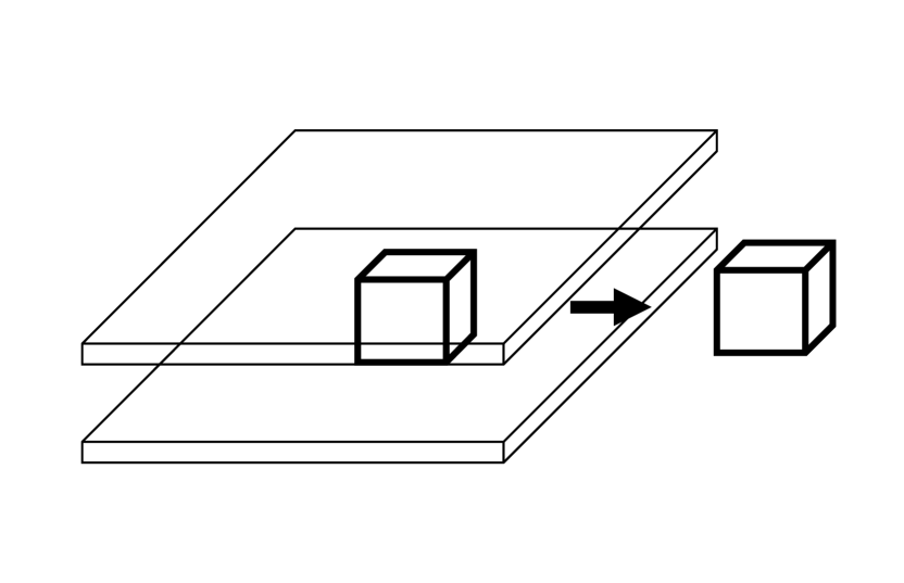
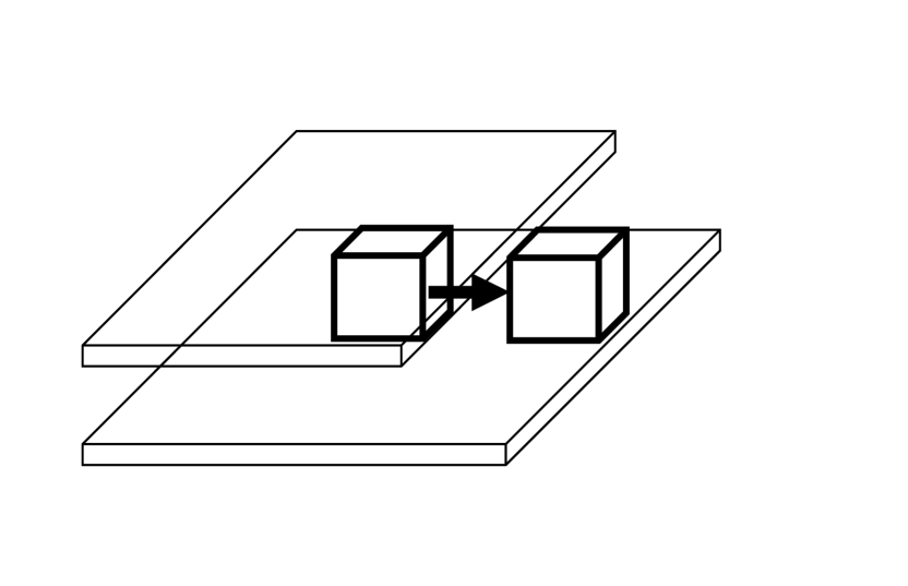
An object in PC (M=2, D=1, C=0) has two maintenance d-states and one detachment d-state. For example, it could be a cube on a desk. The normal direction of the desk surface serves as the pure detachment direction (detachment d-state) and any direction along the desk surface is a maintenance direction (maintenance d-state). In PC, we can consider two types of tasks to move the object: in the detachment direction and in the maintenance direction as shown in Figure 6.
PC-NC detachment motion: the pure detachment direction of the object is along the normal direction of the contact surface. The motion of the object along the direction results in no contact with surface, causing the transition to the maintenance d-state from the detachment d-state and the state of the object becomes NC (M=3, D=0, C=0) from PC. This is a typical example of the Pick-up task.
PC-NC maintenance motion: When moving in the maintenance direction, the infinitesimal motion does not cause any transition of dimensions. The transition to NC and loss of contact only occurs due to the shape of the environment surface. Namely, the transition occurs by moving of the object along the contact surface with maintaining contact with the surface and then reaching the edge of the surface due to the overall shape of the surface. After this point, there is no contact with the surface, and the direction orthogonal to the motion transits from the detachment d-state to the maintenance d-state.
|
|
|---|---|
| (a) | (b) |
In typical robot operations, the first scenario is much more common, and the second one is rare and not very practical. However, for the sake of comprehensive descriptions, the second scenario is also included.
PC-NC-a: detachment motion
This scenario corresponds to a typical Pick-up task. Concerning the motion direction S, a transition occurs from the detachment d-state to the maintenance d-state, and A3 can be applied:
  A3: if F+s < delta-zero AND S = goal-s,
        then reward
In the two orthogonal directions to the motion, T and U, the maintenance d-state is preserved. Therefore, B1 can be applied for the two directions:
  B1: if T = goal-t, then reward
  B1: if U = goal-u, then reward
Combining these reward conditions with AND logic yields the following reward function. In other words, the goal is to eliminate drag force in the motion direction by an infinitesimal motion and reach a specified position, given from the demonstration, by a finite motion.
  Reward PC-NC-a (PTG11 (Pick) task)
    if F+s < delta-zero AND S = goal-s AND
       T = goal-t AND U = goal-u,
      then reward
Note that this corresponds to PTG11 in Ikeuchi et al. (2018).
PC-NC-b: maintenance motion
This case occurs when surface contact disappears at the edge of the environment surface (i.e., table surface) as an example scenario shown in Figure 6 (b).
Regarding the motion direction, the maintenance d-state remains after the transition, and A1 can be applied:
A1: if S = goal-s, then reward
On one hand, one of the two directions orthogonal to the motion, in the example shown in the figure, the direction parallel to the table surface (here we call the T direction) does not undergo a transition in the maintenance d-state before and after the transition. Therefore, B1 can be applied:
B1: if T = goal-t, then reward
On the other hand, the other dimension, the vertical direction in the example (here we call the U direction) undergoes a transition from the detachment d-state to the maintenance d-state. B5 can be applied. In the finite interval before the transition, the detachment d-state is preserved, and in the finite interval after the transition, position control becomes relevant. However, it is necessary to include the condition to confirm that departure from the surface has occurred.
  B5: if NOT(AfterTransition):
        if F-u > delta-collision,
          then penalty
        if F-u < delta-zero, then penalty
      else:
        if F-u < delta-zero AND U = goal-u,
          then reward
Combining these, the following reward function is obtained.
  Reward PC-NC-b
    if NOT(AfterTransition):
      if F-u > delta-collision, then penalty
      if F-u < delta-zero, then penalty
    else:
      if S = goal-s AND T = goal-t AND
         F-u < delta-zero AND U = goal-u,
        then reward
NC-PC-a: attachment motion
In the same way as PC-NC, NC-PC also has two scenarios. Here, please imagine cases where the directions of the arrows are reversed in Figure 6. One corresponds to the common Place task where the detachment d-state is achieved by moving from the direction that will become the detachment direction after the transition, i.e., placing an object from above the contact surface. The other is a race case where the detachment d-state is achieved by approaching the contact surface from the side, causing contact.
When placing an object from above the contact surface, along the motion direction, the maintenance d-state transits to the detachment d-state. A2 can be applied:
A2: if F-s > delta-zero, then reward
In the two orthogonal directions to the motion, the maintenance d-state remains unchanged. B1 can be applied:
  B1: if T = goal-t, then reward
  B1: if U = goal-u, then reward
Therefore, the reward function is as follows:
  Reward NC-PC-a (PTG13 (Place) task)
    if F-s > delta-zero AND T = goal-t AND
       U = goal-u, then reward
Note that this is named PTG13 in Ikeuchi et al. (2018).
NC-PC-b: maintenance motion
In the example shown in the figure, the object moves parallel to the desk surface from the outside of the desk to precisely induces the surface contact on the desk. This task is not advantageous for robot operations, so its frequency of use may not be high. However, it is included here to ensure overall completeness and necessity.
Regarding the motion direction, it remains in the maintenance d-state, and A1 can be applied:
A1: if S = goal-s, then reward
One dimension orthogonal to the motion also remains in the maintenance d-state, and B1 can be applied:
B1: if T = goal-t, then reward
On the other hand, for the remaining orthogonal dimension, a transition from a maintenance d-state to a detachment d-state occurs; B4 can be applied. Before the transition, as there is no physical contact, visual feedback becomes necessary to adjust the position in this direction. After the transition in a finite interval, it is necessary to maintain the detachment d-state.
  B4: if NOT(AfterTransition):
        if |U - feature-u| > delta-gap,
          then penalty
      else:
        if F-u > delta-collision,
          then penalty
        if F-u < delta-zero, then penalty
Therefore, the reward function is as follows:
  Reward NC-PC-b
    if NOT(AfterTransition):
      if |U - feature-u| > delta-gap,
        then penalty
    else:
      if F-u > delta-collision, then penalty
      if F-u < delta-zero, then penalty
      if S = goal-s AND T = goal-t,
        then reward
Figure 7 summarizes the skills related to PC-NC and NC-PC.
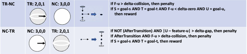
3.4.2 TR-NC and NC-TR
TR-NC
TR (M=2, D=0, C=1) has two maintenance dimensions and one constraint dimension and a typical example of an object in this state is a cube sandwiched between two parallel walls. In this case, the normal direction of the wall is in the constraint dimension. The cube can move in the maintenance directions (i.e., in the directions parallel to the walls). This maintenance motion itself does not cause a state transition of the object in an infinitesimal interval, but the transition occurs due to the shape of the constraint surfaces when it moves for a certain finite interval.
Depending on the shape of the constraint surface, it could transit to NC (M=3, D=0, C=0) or PC (M=2, D=0, C=1) as shown in Figure 8. The TR-NC transition occurs when the edges of the two constraint surfaces are at the same position, and the moving cube simultaneously loses contact with these faces.
|
|
|---|---|
| (a) | (b) |
Regarding the motion direction, it maintains the maintenance d-state before and after the transition, satisfying A1:
A1: if S = goal-s, then reward
One of the dimensions orthogonal to the motion direction maintains the maintenance d-state before and after the transition, satisfying B1:
B1: if T = goal-t, then reward
The remaining orthogonal dimension experiences a sudden disappearance of the constraint surfaces, transiting from the constraint d-state to the maintenance d-state. B8 is applicable:
  B8: if F-u > delta-collision, then penalty
      if F-u < delta-zero AND U = goal-u,
        then reward
In summary,
  Reward TR-NC
    if F-u > delta-collisoin, then penalty
    if S = goal-s AND T = goal-t AND
       F-u < delta-zero AND U = goal-u,
      then reward
NC-TR
This NC (M=3, D=0, C=0) - TR (M=2, D=0, C=1) is the reverse skill of the earlier TR-NC, and for example, a skill such as placing a book in the air into the space between two books would cause the transition from one maintenance dimension to one constraint dimension. Along this dimension, this skill requires the use of vision, as there is no surface contact before the transition.
As for the direction of motion, A1 is applicable since it remains a maintenance d-state.
A1: if S = goal-s, then reward
One direction orthogonal to the motion direction remains in a maintenance d-state before and after the transition, and B1 is applied:
B1: if T = goal-t, then reward
For the dimension for which the maintenance d-state changes to the constraint d-state (the normal direction of the book in the above example), B9 can be applied and visual information must be used.
  B9: if NOT(AfterTransition):
        if |U - feature-u| > delta-gap,
          then penalty
      else:
        if F-U > delta-collision,
          then penalty
In summary,
  Reward NC-TR
    if NOT(AfterTransition):
      if |U - feature-u| > delta-gap,
        then penalty
    else:
      if F-u > delta-collision, then penalty
      if S = goal-S AND T = goal-t,
        then reward
Figure 9 summarises the skills of TR-NC and NC-TR.
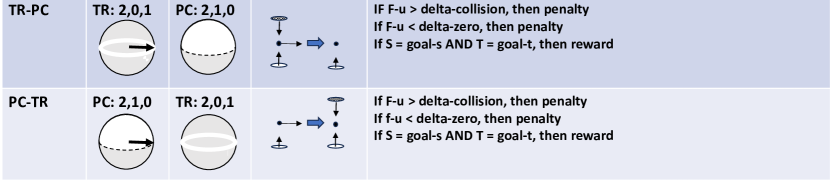
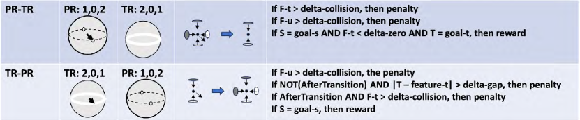
3.4.3 TR-PC and PC-TR
TR-PC
As shown in Figure 8 (b), the TR-PC transition occurs in the case that the edge positions of the top and bottom surfaces are different and the top surface loses contact while the bottom surface is still in contact in the finite motion.
Along the motion direction, since the maintenance d-state is preserved before and after the transition, A1 can be applied and the terminal point of the skill can be specified as the positional information given from the demonstration.
A1: if S = goal-s, then reward
One of the two dimensions orthogonal to the motion remains in the maintenance d-state before and after the transition. Therefore, with B1, positional information can also be specified for this dimension.
B1: if T = goal-t, then reward
In the remaining dimension, the constraint d-state transits to the detachment d-state. In the above example, before the transition, the cube is constrained to the top and the bottom surfaces, and after the transition, it detaches from the top surface by sliding the bottom surface. In this direction, B7 can be applied.
  B7: if F-u > delta-collision, then penalty
      if F-u < delta-zero, then penalty
In summary,
  Reward TR-PC
    if F-u > delta-collision, then penalty
    if F-u < delta-zero, then penalty
    if S = goal-s AND T = goal-t,
      then reward
PC-TR
Let us consider a cube sliding on a table into a gap between the table surface and a parallel upper wall. A state transition occurs from PC (M=2, D=1, C=0) on the table to TR (M=2, D=0, C=1) in the gap. As described above, this sliding motion automatically causes such transition and if this cube collides the top wall due to the difference in size, the skill is fundamentally infeasible due to the difference between the sizes of the object (the cube) and the environment (the walls).
The motion direction remains in the maintenance d-state. Therefore, A1 is applicable:
A1: if S = goal-s, then reward
One dimension orthogonal to the motion direction remains in the maintenance d-state, i.e., the horizontal direction in the above example, allowing for the application of B1:
B1: if T = goal-t, then reward
On the other hand, for the dimension transiting from the detachment d-state to the constraint d-state, i.e., the normal direction of the table surface in the above example, B6 can be applied. Essentially, by controlling to maintain the detachment d-state, i.e., keeping the surface contact, the detachment d-state naturally transits into the constraint d-state.
  B6: if F-u > delta-collision, then penalty
      if F-u < delta-zero, then penaly
In summary,
  Reward PC-TR
    if F-u > delta-collision, then penalty
    if F-u < delta-zero, then penalty
    if S = goal-s AND T = goal-t,
      then reward
Figure 10 summarises the skills of TR-PC and PC-TR.
3.5 Other interstate transitions
The similar discussions can be applied for other interstate transitions. For these transitions, only brief descriptions and results are listed below. Detailed derivations of the reward functions are given in Appendix A and Figures 11 to 18 show their reward functions.
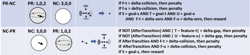
3.5.1 PR-NC and NC-PR
PR (M=1, D=0, C=2) - NC (M=3, D=0, C=0) involves such as completely pulling a peg out of the hole, while NC-PR involves the opposite skill of swiftly inserting a peg into a hole. Since there is no physical contact with the environment before the transition, it is necessary to determine the hole position using visual sensors.
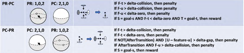
3.5.2 PR-PC and PC-PR
The PR (M=1, D=0, C=2) - PC (M=2, D=1, C=0) transition occurs, for example, when pulling a peg inside a hole, of which a part of the side is extended externally. Thus, when the peg comes out, contact with the extended surface persists, leading to a detachment d-state instead of a maintenance d-state in that direction unlike the PR-NC skill.
3.5.3 PR-TR and TR-PR
PR (M=1, D=0, C=2) - TR (M=2, D=0, C=1) is a skill required in situations where, using the previous example, a pair of opposite surfaces extend outside the hole, and despite the transition from the constraint d-state to the maintenance d-state occurs in the other orthogonal direction, this direction remains in the constraint d-state.
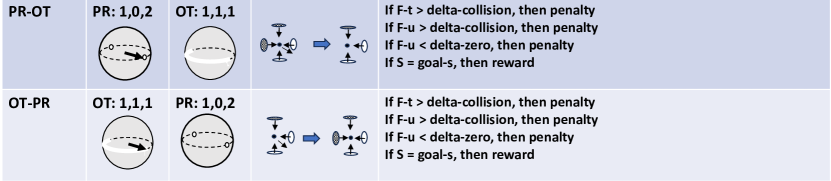
3.5.4 PR-OT and OT-PR
PR (M=1, D=0, C=2) - OT (M=1, D=1, C=1) is a skill required in situations where surface contact continues in three directions.
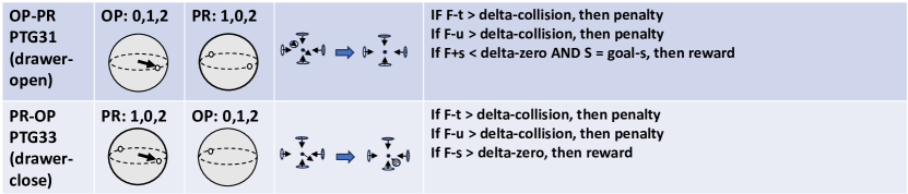
3.5.5 OP-PR and PR-OP
OP (M=0, D=1, C=2) is like a peg that has reached the bottom of a hole and can move only in the half direction away from the bottom, with two orthogonal directions to this direction constrained, while PR (M=1, D=0, C=2) is like a peg that remains in the middle of a hole and can move along the hole in both directions. In the previous paper, we name OP-PR and PR-OP as PTG31 (Drawer-opening) and PTG33 (Drawer-closing).
3.5.6 OT-NC and NC-OT
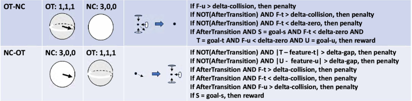
OT (M=1, D=1, C=1) - NC (M=3, D=0, C=0) is a skill that involves pulling an object along the detachment surface, not in the normal direction of the detachment surface, when the object is surrounded by a pair of opposing directions and another direction. In the reverse skill, NC-OT, visual feedback is required.
3.5.7 OT-PC and PC-OT
The previous OT-NC transition occurs while an object in the center is in motion with maintaining contact with the surrounding environment, the contact ends simultaneously due to the shape of the environment. On the other hand, the OT (M=1, D=1, C=1)-PC (M=2, D=1, C=0) transition occurs, while the object is moving, contact with the environment continues in one direction. In this OT - PC transition, the control differs depending on whether the contact with original detachment surface continues or the contact with a part of the surfaces that created the constraint d-state persists: (a) the detachment d-state continues and (b) the constraint d-state transits to the detachment d-state. See the details in Appendix.
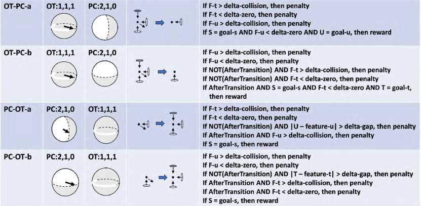
3.5.8 OT-TR and TR-OT
Regarding the transition of OT (M=1, D=1, C=1) to TR (M=2, D=0, C=1), there are two cases: (a) motion to break the face contact of the detachment surface and (b) motion to maintain the face contact to the detachment surface. Also see the details in Appendix.
3.6 Intrastate transition
This paper defines a task as one unit of robot motion that causes a transition in surface contact states. In a broader sense, we define a transition to the same state as one type of state transitions. A unit of motion to the same state is also defined as a task. This is because some motions that maintain the same states are important for the implementation of some of semantic tasks (Ikeuchi et al. (2021)). For example, a task that transits from the PC state to the PC state corresponds to the STG2 of semantic tasks, Wiping task. In the following, we will analyze reward functions for the implementation of these intrastate transition motion.
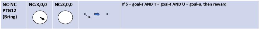
3.6.1 NC-NC
The skill of the robot corresponding to NC (M=3, D=0, C=0) - NC is a Bring task and PTG12 in Ikeuchi et al. (2018). It is the unconstrained motion to bring an object from one position to another.
For the motion direction, the maintenance d-state is maintained, A1 can be applied:
A1: if S = goal-s, then reward
For the two dimensions orthogonal to the motion direction, B1 is also applicable since the maintenance d-state is maintained.
  B1: if T = goal-t, then reward
  B1: if U = goal-u, then reward
Putting these together:
  Reward NC-NC (PTG12 (Bring) task)
    if S = goal-s AND T = goal-t AND
       U = goal-u, then reward
Figure 19 shows the summary of the NC-NC skill.
3.6.2 PC-PC
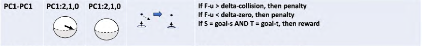
The PC state includes three classes of solutions from the Kuhn-Tucker theory (Kuhn and Tucker (1957)): PC1 (M=2, D=1, C=0), PC2 (M=1, D=2, C=0), and PCN (M=0, D=3, C=0), whose solution areas are hemispherical, cresentic, and polygonal regions on the Gaussian sphere, respectively. For the sake of analytical simplicity, this paper assumes that interstate transitions only occur from/to PC1 and transitions among PC1, PC2, and PCN are treated as intrastate transitions, which will be analyzed in this subsection.
PC1-PC1
In the intrastate transition from PC1 (M=2, D=1, C=0) to PC1, the object must remain in contact with the contact surface during the motion. In the motion direction, A1 is applicable because the maintenance d-state continues in that direction.
A1: if S = goal-s, then reward
In one of the orthogonal dimension to the motion, B1 is applicable since the maintenance d-state is maintained.
B1: if T = goal-t, then reward
In the remaining dimension, B2 is applicable since the detachment d-state is maintained.
  B2: if F-u > delta-collision, then penalty
      if F-u < delta-zero, then penalty
Putting these together, we obtain:
  Reward PC1-PC1 (STG2 (Wipe) task)
    if F-u > delta-collision, then penalty
    if F-u < delta-zero, then penalty
    if S = goal-s AND T = goal-t,
      then reward
Figure 20 shows the summary of the PC1-PC1 skill.
PC1-PC2
The transition from PC1 (M=2, D=1, C=0) to PC2 (M=1, D=2, C=0) is caused when an object in motion while maintaining contact with one surface collides with another surface and the motion direction becomes the detachment d-state. Thus, as for the motion direction, A2 is applicable:
A2: if F-s > delta-zero, then reward
In one orthogonal dimension to the motion, B1 is applicable because the maintenance d-state is maintained.
B1: if T = goal-t, then reward
In the remaining dimension that maintains the contact, the detachment d-state is maintained and B2 is applicable.
  B2: if F-u > delta-collision, then penalty
      if F-u < delta-zero, then penalty
We obtain:
  Reward PC1-PC2
    if F-u > delta-collision, then penalty
    if F-u < delta-zero, then penalty
    if F-s > delta-zero AND T = goal-t,
      then reward
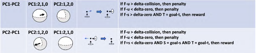
c) PC2-PC1
A3 is applicable to the motion direction because the contact surface will be broken due to the motion and the transition from the detachment d-state to the maintenance d-state occurs:
  A3: if F+s < delta-zero and S = goal-s,
        then reward
In one orthogonal dimension to the motion, the maintenance d-state is maintained and B1 is applicable:
B1: if T = goal-t, then reward
In another orthogonal dimension to the motion, the object maintains the surface contact during the motion and the detachment d-state is maintained. B2 is applicable:
  B2: if F-u > delta-collision, then penalty
      if F-u < delta-zero, then penalty
We can summarize:
  Reward PC2-PC1
    if F-u > delta-collision, then penalty
    if F-u < delta-zero, then penalty
    if F+s < delta-zero AND S = goal-s AND
       T = goal-t, then reward
Figure 21 shows the summary of the skills of PC1-PC2 and PC2-PC1.
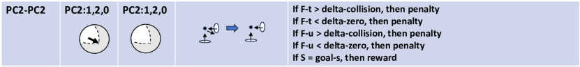
PC2-PC2
In PC2 (M=1, D=2, C=0), a one-dimensional maintenance d-state exists. Along this dimension, a motion to maintain the state is possible. Thus, A1 is applicable.
A1: if S = goal-s, then reward
Concerning the two dimensions orthogonal to the motion, the detachment d-state is maintained with keeping contact to the environment surfaces. B2 is applicable.
  B2: if F-t > delta-collision, then penalty
      if F-t < delta-zero, then penalty
  B2: if F-u > delta-collision, then penalty
      if F-u < delta-zero, then penalty
In summary,
  Reward PC2-PC2
    if F-t > delta-collision, then penalty
    if F-t < delta-zero, then penalty
    if F-u > delta-collision, then penalty
    if F-u < delta-zeron, then penalty
    if S = goal-s, then reward
Figure 22 shows the PC2-PC2 skill.
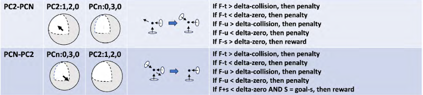
PC2-PCN
PC2 (M=1, D=2, C=0) has one maintenance dimension that allows motion while maintaining contact with two different surfaces. This dimension corresponds to the base of the crescent-shaped cone of a Gaussian sphere. When the object collides with a third surface during motion along this maintenance dimension, the transition from PC2 to PCN (M=0, D=3, C=0) occurs.
Regarding the motion direction, since the transition from the maintenance d-state to the detachment d-state occurs, A2 is applicable:
A2: if F-s > delta-zero, then reward
In the two dimensions orthogonal to the motion direction, the detachment d-state is maintained, so B2 is applicable:
  B2: if F-t > delta-collision, then penalty
      if F-t < delta-zero, then penalty
  B2: if F-u > delta-collision, then penaly
      if F-u < delta-zero, then penalty
In summary,
  Reward PC2-PCN
    if F-t > delta-collision, then penalty
    if F-t < delta-zero, then penalty
    if F-u > delta-collision, then penalty
    if F-u < delta-zero, then penalty
    if F-s > delta-zero, then reward
PCN-PC2
There is no maintenance dimension in PCN (M=0, D=3, C=0), all the possible motions are in the detachment dimensions. Among those possible motions, the transition from PCN to PC2 occurs when the object departs from one surface while maintaining contact with the remaining surfaces. Therefore, concerning the motion direction, the transition from a detachment d-state to a maintenance d-state takes place. A3 is applicable:
  A3: if F+s < delta-zero AND S = goal-s,
        then reward
In the two dimensions orthogonal to the motion direction, the detachment d-state is maintained, so B2 is applicable.
  B2: if F-t > delta-collision, then penalty
      if F-t < delta-zero, then penalty
  B2: if F-u > delta-collision, then penalty
      if F-u < delta-zero, then penalty
In summary,
  Reward PCN-PC2
    if F-t > delta-collision, then penalty
    if F-t < delta-zero, then penalty
    if F-u > delta-collision, then penalty
    if F-u < delta-zero, then penalty
    if F+s < delta-zero and S = goal-s,
      then reward
Figure 23 shows the skills of PC2-PCN and PCN-PC2.
3.6.3 TR-TR
TR (M=2, D=0, C=1) - TR is a transition where an object sandwiched between two walls moves between them. The reward function is given in Figure 24. For the detailed derivation, please refer to Appendix B.

3.6.4 OT-OT
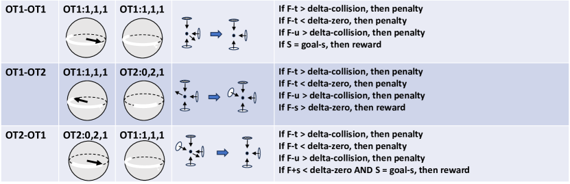
In the OT state, there are two sub-classes: OT1 (M=1, D=1, C=1) and OT2 (M=0, D=2, C=1). Similar arguments to the case of the PC state can be applied to transitions between these sub-classes. Reward functions for these skills are given in Figure 25. For detailed derivation, please refer to Appendix B.
3.7 Rotational skills
For rotational motion, states can be defined in Figure 2 (b), and skills can be defined for transitions between these states shown in Figure 3 (b).
In the case of translational motion, the direction of the screw axis coincided with the direction of motion of the object. In the case of rotational motion, on the other hand, the axis direction and the direction of motion are orthogonal, and in a finite interval of motion, the trajectory is a curvilinear motion. Nevertheless, the infinitesimal motion at each infinitesimal unit time can be assumed to be a translational motion orthogonal to the axis. By considering a local coordinate system in which the direction of motion at that time is S and the orthogonal directions to the motion direction are T and U, we can develop an argument similar to that for the translational case.
We will take an example, the OR (M = 0, D = 1, C = 2) - RV (M = 1, D = 0, C = 2) transition, corresponding to a Door-opening task, which appears particularly frequently. OR corresponds to a state where the door is closed, and rotation is possible only in the direction of detachment (i.e., opening direction). The transition in the direction of rotation is from the detachment d-state to the maintenance d-state, and A3 can be applied. In other words, the drag force in the direction of rotation, F+s, is eliminated, and the skill concludes when a certain predetermined rotation angle, goal-s, given by the demonstration, is reached.
  A3: if F+s < delta-zero AND S = goal-s,
        then reward
The two other dimensions are both constrained, resulting in B3. In other words, attempting to rotate with infeasible displacement forcibly will generate drag forces, F-t and F-u. Therefore, it is necessary to maintain these forces below a certain threshold.
  B3: if F-t > delta-collision, then penalty
  B3: if F-u > delta-collision, then penalty
In summary,
  Reward OR-RV (PTG51 (Door-open) task)
    if F-t > delta-collision, then penalty
    if F-u > delta-collision, then penalty
    if F+s < delta-zero AND S = goal-s
      then reward
A similar consideration yields the following reward functions for RV-OR and RV-RV skills.
  Reward RV-OR (PTG53 (Door-close) task)
    if F-t > delta-collision, then penalty
    if F-u > delta-collision, then penalty
    if F-s > delta-zero, then reward
  Reward RV-RV (PTG52 (Door-adjust) task)
    if F-t > delta-collision, then penalty
    if F-u > delta-collision, then penalty
    if S = goal-s, then reward
4 Implementation of skill-agent library
4.1 Current skill-agent library
The manipulation skill-agent library currently consists of a commonly used set of skill agents, including
-
•
PC-NC-a (PTG11, Pick) skill agent
-
•
NC-NC (PTG12, Bring) skill agent
-
•
NC-PC-a (PTG13, Place) skill agent
-
•
OP-PR (PTG31, Drawer-open) skill agent
-
•
PR-PR (PTG32, Drawer-adjust) skill agent
-
•
PR-OP (PTG33, Drawer-close) skill agent
-
•
OR-RV (PTG51, Door-open) skill agent
-
•
RV-RV (PTG52, Door-adjust) skill agent
-
•
RV-OR (PTG53, Door-close) skill agent
-
•
PC1-PC1 (STG2, Wipe) skill agent
This set adequately allows our home service robot to perform tasks. However, if needed, it can be extended using the method outlined in this paper.
In order to build an end-to-end system, grasping skill agents are also necessary. The grasping skill agents described in Saito et al. (2022) have been implemented for Shadow-hand and Fetch Parallel-gripper in the grasp skill-agent library. Currently, this library includes:
-
•
Active-force grasp skill agent
-
•
Passive-force grasp skill agent
-
•
Lazy-closure grasp skill agent
The execution of a skill agent, in the case of the OP-PR task, is illustrated in Figure 26. First, a sequence of task models is generated from the human demonstration. Each task model has the skill parameters to execute that task based on the demonstration. In the OP-PR task, the direction of pushing the drawer is stored as Axis direction.
4.2 Reinforcement learning environment
Many skill agents require prior learning policies to adjust motion directions based on the force feedback with reward functions. For training those skill agents, we developed a reinforcement learning environment that parallelized the PPO algorithm in Stable Baselines3222https://stable-baselines3.readthedocs.io/en/master/.
To build the learning environment, we used PyBullet333https://pybullet.org/wordpress/ as a simulator and obtained the necessary policies for each skill agent through reinforcement learning. For example, we set up the environment shown in Figure 27 in the simulator that satisfies the surface contact state. Gravity is set to 0 to keep the environment as simple as possible. We assumed that the object is already grasped by a hand and they are integrated into one unit. Since the estimation of the normal direction of the contact surface may contain some errors, domain randomization was used to add the errors in the training. The contact was assumed to be represented by an elastic body, and hardware compliance was simulated by setting the spring and damper coefficients.
The control side of each skill agent is described by a force relationship. It is assumed that the actual robot is equipped with a 6-axis force sensor. However, due to the difference in physical parameters between the simulator and the actual machine, it is difficult to simulate the magnitude of the force accurately. Therefore, to ensure that the policy obtained in the simulation can be implemented on the actual robot, we used the unit vector of the force instead of the original value as the states for the reinforcement learning.
| (2) |
The values of the force sensor shall be represented by converting them to the world coordinate system using the posture of the object obtained on the simulator and the FK of the actual machine.
In some cases, coarsely discretized force magnitudes were used to convey force magnitude information to the reinforcement learning.
| (3) |
Here, is an arbitrary constant that determines the degree of discretization, and different values are used for simulator and the actual machine to bridge the gap between the simulator and the actual machines.
4.3 Skill agents
4.3.1 PC-NC-a (Pick), NC-NC (Bring), NC-PC-a (Place) skill agents
These skills are considered to be the most basic robot skills. Reinforcement learning is not required for this group.
The PC-NC-a skill agent can be described by the following control rule.
  if F+s < delta-zero AND S = goal-S AND
     T = goal-t AND U = goal-U, then reward
The skill corresponds to the task model shown in Figure 28 (Ikeuchi et al. (2021)). In the figure, (get ACT name) etc. are daemon functions to obtain the respective values and to store in these slots:
-
•
ACTOR slot - right hand or left hand
-
•
OBJECT slot - object name
-
•
EDC slot - Hand configuration at the end of the task obtained from the demonstration (EnD Configuration)
-
•
DTD slot - Direction of hand movement at the start of the task obtained from the demonstration (DeTachment Direction)
-
•
EDL Labanotation of human pose at the end of the task obtained from the demonstration (EnD Labanotation (Ikeuchi et al. (2018)))
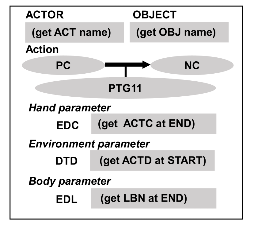
Since the position of the hand before the execution of the skill is known from the end position of the previous skill, the values of goal-s, goal-t, ant goal-u can be calculated using the value in the EDC slot. The skill ends when the target position is reached. The NC-NC skill agent is implemented in the same way.
The NC-PC-a skill agent, also called PTG13 (Place), is also almost the same as the PC-NC-a skill agent except for the termination condition. The end position obtained from the demonstration includes an observation error, thus, the control algorithm,
    if F-s > delta-zero AND T = goal-t AND
       U = goal-U, then reward
moves the hand to the target position given by the demonstration, while the skill ends when the value of the drag force against the direction of the motion exceeds the threshold value.
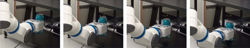
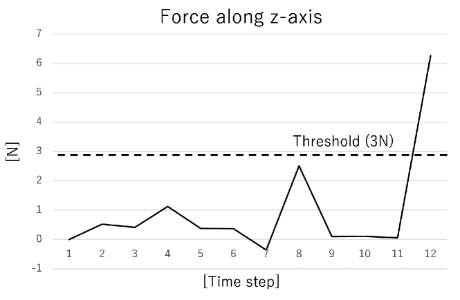
Here we show the results of the execution using a real robot to confirm if the implemented skill agents are working correctly. Figure 29 shows the execution of the NC-PC-a skill agent. Figure 30 shows the change in force sensor values. To remove the effect of gravity, the force at the start of the skill is retained and the difference from it is calculated; by using the relationship between the force sensor coordinate system in the robot coordinate system obtained from FK, the force values are converted to those in the world coordinate system. Figure 30 shows the changes in the z-axis direction (vertical upward). It can be confirmed that the force increases due to the drag force generated when the grasping object comes into contact with the surface. Delta-zero was set to 3 [N]. The contact was detected at time 12 and this skill was completed correctly.
4.3.2 OP-PR (Drawer-open), PR-PR (Drawer-adjust), PR-OP (Drawer-close) skill agents
These skill agents can be described by the following control rule without the termination condition.
    if F-t > delta-collision, then penalty
    if F-u > delta-collision, then penalty
All the skills need to satisfy the same rule. Generally, the skill parameters (e.g., drawing direction) observed in the demonstration include errors. Thus, it is necessary to train these skill agents using RL. In order to reduce the training effort, we train the PR-PR skill agent first, and then add the program to decide the terminal condition.
The state in PR can be represented by setting the direction of the feasible displacement. The skill agnet needs the force information for feedback in the execution. Thus, the state in RL can be designed as follows:
-
•
the direction of the feasible displacement: ,
-
•
the unit vector of the force: ,
where is the force value in time . The action in RL is the modification of the currently estimated direction, . Given the modification, the displacement direction at time is calculated by the following equation:
The PR-PR skill agent requires to satisfy F-t delta-collision and F-u delta-collision. If the force exerted by the constraint would be reduced, these two conditions tend to be satisfied. Thus, the reward function can be formulated as follows:
| (4) |
The episode in RL training is terminated after the predefined duration. Figure 31 shows the reward curve. The training was terminated after one million steps. The reward curve looks converging.
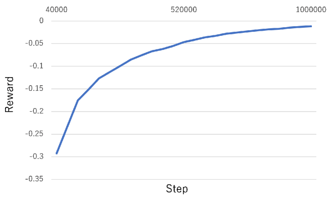
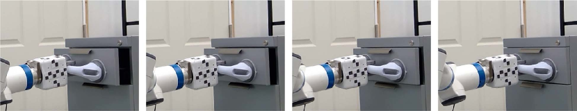
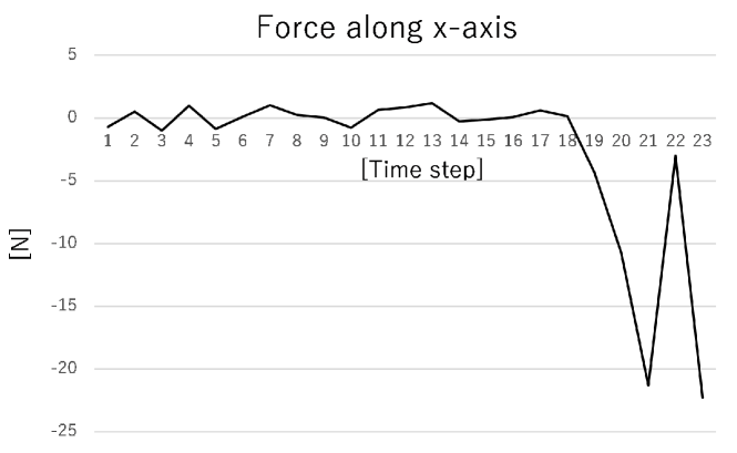
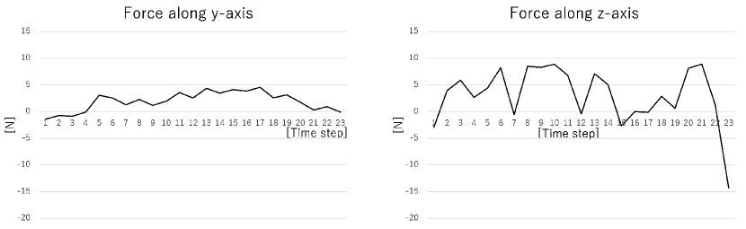
Figure 32 shows the execution of the PR-OP skill agent by an actual robot. We set the distance of the displacement at each step to 5 [mm]. Figure 33 shows the force along the drawing direction. Closing the drawer generates a large drag force, which allows us to determine the termination of the PR-OP skill. This drawer has a locking mechanism that prevents it from opening accidentally on its own. It can be seen that a large force is generated at time 21 before the lock, then the force decreases, and finally a large force is generated when the drawer is completely closed. Figure 34 shows the changes in the force values in the horizontal and vertical directions, orthogonal to the drawing direction. Although there are some situations where unwanted force is generated during the execution, the drawing direction is modified to suppress the generation of force by the PR-OP skill agent. However, instability is confirmed because of the deviation from the physical condition of PR-PR around the time it approaches the locking mechanism (See force along the z-axis), but the PR-OP skill agent achieved the task without any troubles because of the short time from there to the closure.
4.3.3 OR-RV (Door-open), RV-OR (Door-close), RV-RV (Door-adjust) skill agents
These skill agents can be described by the following control rule without the termination condition.
    if F-t > delta-collision, then penalty
    if F-u > delta-collision, then penalty
All the skills need to satisfy this rule. Generally, the skill parameters (e.g., the configuration of the rotation axis) observed in the demonstration include errors. These skill agents also need to be trained using RL. As described above, the infinitesimal displacement at each moment can also be interpreted as an infinitesimal translation tangential to the rotation. The whole trajectory can be regarded as the pieces of the infinitesimal translation, where the translation direction is gradually changed. We can regard that the training of RV-RV is the same as that of PR-PR, since the target displacement at both skills needs to be modified following the constraint (e.g., force feedback) of the (infinitesimal) translation; the control rule is the same.
The state of RV is represented by the infinitesimal feasible translation. The skill needs the force information of the feedback. The state in RL can be formulated as follows:
-
•
estimated infinitesimal translation: ,
-
•
normalized force: .
The action is also the same as that in the PR-PR skill agent as . The modification is also the same as
The difference between the RV-RV and PR-PR skills is that the RV-RV skill involves the orientation changes with respect to the modification of the displacement. Thus, we add the orientation changes to the PR-PR skill agent; if the displacement is changed by , the orientation of the hand, as well as the next motion direction, are modified by around the center of the grasping points. See Figure 35.
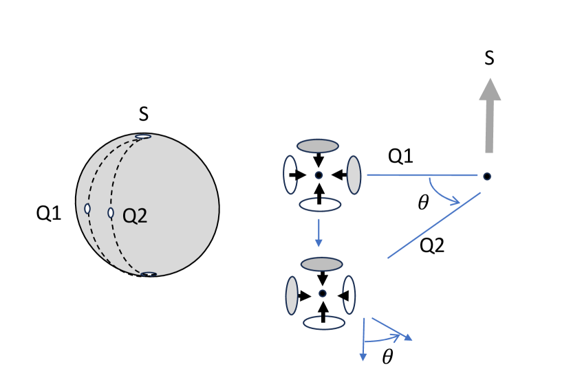
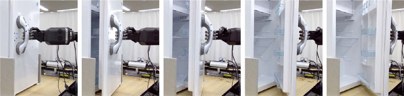
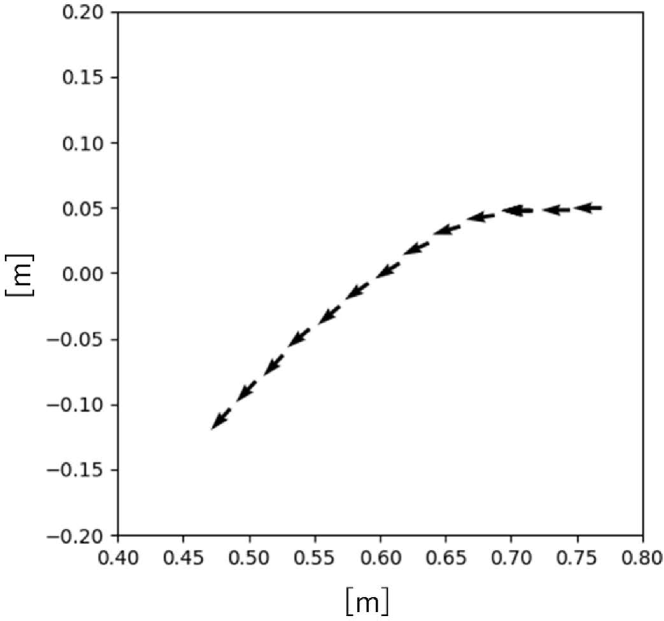
Figure 36 shows the execution of the OR-RV skill agent by an actual robot. In this case, we also set the distance of the displacement at each step to 5 [mm]. Figure 37 shows the trajectory of the center of the grasping points and the estimated opening directions. As can be seen, the robot tried to follows the curvilinear trajectory to open the door and the estimated opening direction is modified to follow the tangential direction of the trajectory.
4.3.4 PC1-PC1 (Wipe) skill agent
The control rule is formulated as follows:
  if F-u > delta-collision, then penalty
  if F-u < delta-zero, then penalty
  if S = goal-s AND T = goal-t, then reward
Generally, the skill parameters (e.g., the surface normal) observed in the demonstration include errors. Thus, this also needs to be trained using RL.
From the control rule, the force along the normal direction, F-u, should be less than delta-collision and more than delta-zero. Then, the PC1-PC1 skill is realized by controlling F-u to be an appropriate value in between. Specifically, if the value of the force sensor just when contacting each other is , the target force is calculated by the following equation:
| (5) |
where is the observed surface normal. The above equation will simply change the value of the force along the normal direction to . If the value of the force sensor at time is , the state of RL can be defined as follows:
-
•
surface normal: ,
-
•
target displacement direction: ,
-
•
Normalized difference between current and target forces: ,
where . Unlike the cases of the PR-PR and RV-RV skill agents, which merely reduce the norm of the force, the PC1-PC1 skill agents need to consider the magnitude of the force in order to control F-u to approach to . Therefore, a coarse discretization of the magnitude of is also included as a state. In other words, we add to the state the following element:
-
•
The information on the magnitude of the force: .
The action in RL is defined as the modification of the displacement along the normal direction, and the reward function is as follows:
| (6) |
The first condition corresponds to the case of delta-collision and the second condition corresponds to the case of delta-zero. The third condition contributes to approaching to the target force. The termination condition of the episode is as follows:
-
•
F-u delta-collision, i.e., .
-
•
F-u delta-zero, i.e., the contact is detached.
-
•
the predetermined duration is past.
If the third condition is achieved, we regard that the skill is succeeded and is further added to the reward.
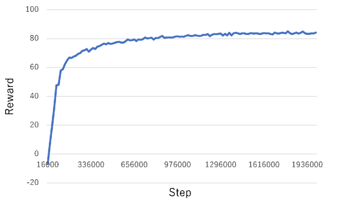
Figure 38 shows the reward curve. We finished training after two million steps. The reward looks converging.
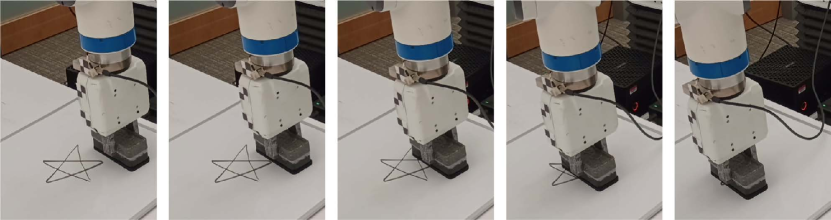
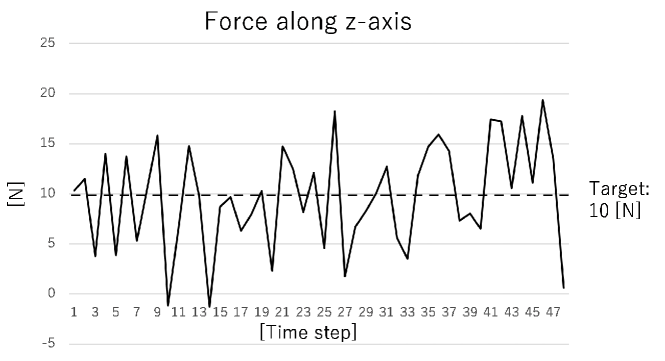
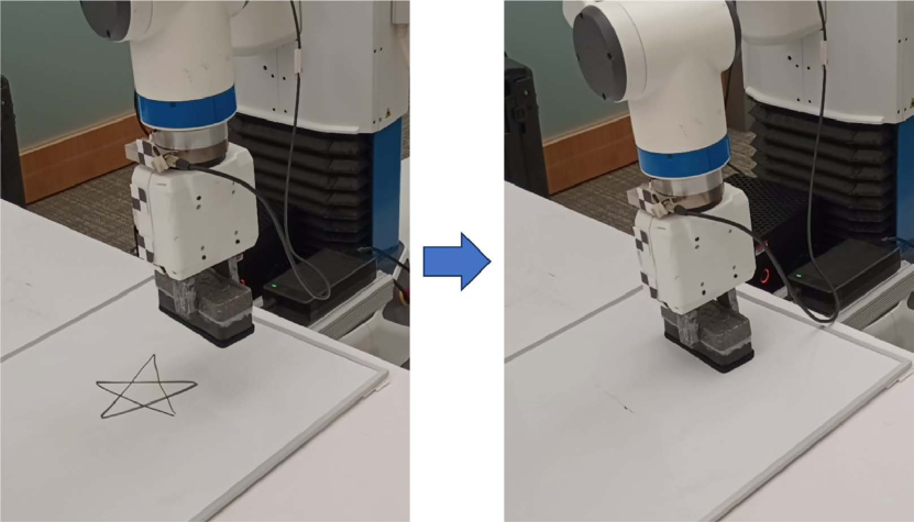
Figure 39 shows the execution of the PC1-PC1 skill agent by an actual robot. The displacement for each step is 5 [mm] in the target translational direction plus the modification outputted by the skill agent. It can be seen that the motion is modified to achieve the target of 10 [N]. As shown in Figure 41, the PC1-PC1 (Wipe) skill agent was actually able to erase the drawing on the white board. Theoretically, as is increased, the degree of feedback to the force value can be reduced. Further improvement of control may be possible by adjusting .
5 Working system
This section describes how the implemented skill agents function in a reusable manner within the end-to-end Learning-from-observation system.
5.1 Observation station
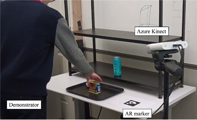
Figure 42 shows the observation station. For observation during the demonstration, we utilized an RGB-D camera, specifically Azure Kinect by Microsoft. To ensure alignment in the orientation between the robot coordinates and the demonstration coordinates, we employed an AR marker. This alignment enables the robot to replicate the demonstrated task sequence, achieving the same displacement while incorporating collision avoidance measures. Note that the locations of the objects do not have to be exactly the same, although they are assumed to be approximately the same during the demonstration and runtime. Any small differences are accommodated by the respective skill agents.
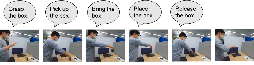
The demonstration employed a stop-and-go approach, allowing the demonstrator to explicitly instruct the system to break down the action sequence into a task sequence. Furthermore, the demonstrator can teach the system collision avoidance paths when carrying objects by explicitly adding way points as stop motions. At each stop, the demonstrator provided verbal descriptions of the task, such as “grasp the box” or “pick up the box,” thereby assisting the system in task recognition.
From the explanation and the demonstration image sequences, the tasks and their skill parameters can be estimated (Wake et al. (2021)). Initially, the type of each task is estimated. Subsequently, the skill parameters for each task are determined by analyzing the task sequence again using the daemon functions.
5.2 Hand motion to body motion under hardware-level reusability
Using IK, we transform hand motions outputted by the skill agent into body motions. A typical IK solver, such as Beeson and Ames (2015), minimizes the difference between the desired hand pose and the pose of the hand obtained through forward kinematics under a certain joint configuration. Generally, there are multiple solutions that satisfy the target hand pose and IK sometimes outputs unexpected body pose. As the degrees of freedom of a robot increase, the likelihood of unexpected poses occurring becomes larger. This issue is addressed by using a Labanotation-based IK solver with the body-role division algorithm (Sasabuchi et al. (2021)).
The Labanotation-based IK solver with the body-role division avoids the unexpected poses. In Labanotation (Hutchinson-Guest (1970); Ikeuchi et al. (2018)), the pose of each limb is represented by 26 discretized directions and there is a margin to achieve a certain target Labanotation pose. The Labanotation pose is obtained from the demonstration (one of the skill parameters). We solve IK as long as the joint angles do not go outside the specified range given by the Labanotation pose.
5.3 Robot testbed
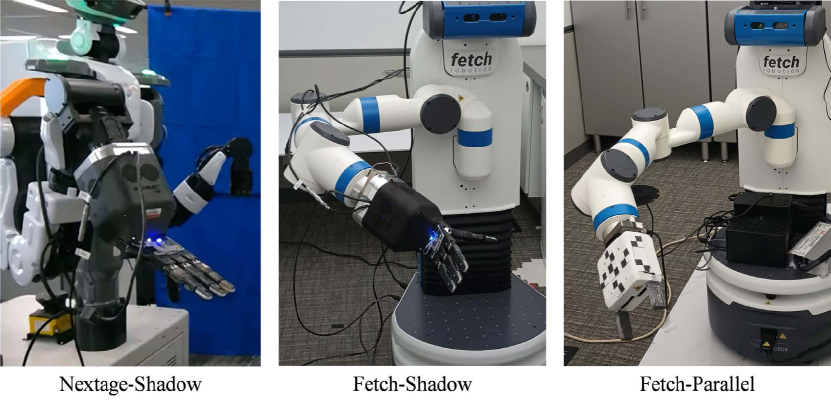
We used three testbed robots shown in Figure 44. Both robots run on ROS (Quigley (2009)). The first (refered to as Nextage-Shadow) was Nextage, Kawada Robotics444https://www.kawadarobot.co.jp/en/nextage/. It has two arms and each arm has six DOF. It also has one DOF in the waist (rotation around the vertical axis). In this paper, we used only the right arm, neither the left arm nor waist, to perform tasks. The right arm was equipped with 6-axis force/torque sensor, FFS Series, Leptrino555https://www.leptrino.co.jp/product/6axis-force-sensor (Japanese) and Shadow Dexterous Hand Lite, Shadow Robotics666https://www.shadowrobot.com/dexterous-hand-series/, as a robot hand. Nextage was equipped with a stereo camera to observe an environment in a 3-dimensional space.
The second (referred to as Fetch-Shadow) was Fetch Mobile Manipulator, Fetch Robotics777https://fetchrobotics.com/fetch-mobile-manipulator/. It has one arm with 7 DOF, 1 DOF in the waist (moving up and down), and 2 DOF in a mobile base. It was also equipped with Leptrino FFS Series and Shadow Dexterous Hand Lite. We do not use a mobile base during manipulation. It was equipped with an RGB-D camera, Primesense Carmine 1.09, to observe an environment. The third (referred to as Fetch-Parallel) was also Fetch Mobile Manipulator. But it was equipped with an original parallel gripper in place of Shadow Dexterous Hand Lite.
6 Demonstration
To demonstrate hardware-level reusability in the learning-from-observation framework, we applied the four task sequences, place-on-plate demo, shelf-sequence demo, throw-away demo, and open-fridge demo to the three different robots, Nextage-Shadow, Fetch-Shadow, and Fetch-Parallel. The place-on-plate demo consists of grasping the box, picking up the box from a table, bringing the box, placing the box on a plate, and releasing the box (See Figure 43). The shelf-sequence demo consists of grasping the cup, picking up the cup, three repetitions of bringing the cup, and releasing the cup (See Figure 46). The throw-away demo consists of picking up the red can, bringing the can, and releasing the can (See Figure 47). The open-fridge demo consists of grasping the handle and opening the fridge (see Figure 48). All the execution videos can be seen from https://j-taka.github.io/research/hardware_level_reusability.html.
6.1 Place-on-plate Demo
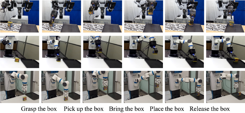
For performing the place-on-plate demonstration, we first demonstrated the task sequence in front of Azure Kinect. As the result, the task sequence was recognized as Active-force grasp, PC-NC-a (PTG11), NC-NC (STG12), NC-PC-a (PTG13), and Release. After obtaining the task sequence, the skill parameters were estimated by observing the task sequence again. Figure 45 shows the execution by the three robots. By executing the task sequence as the same as the observed one, the three robots executed the same task sequence.
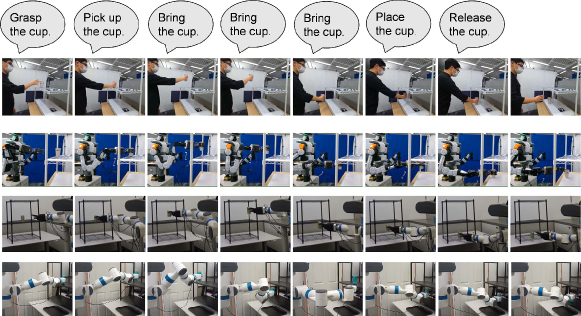
6.2 Shelf-sequence demo
Figure 46 shows the result from the demonstration to the execution of the shelf-sequence demo by the three robots. The task sequence was recognized as Passive-force grasp, PC-NC-a (PTG11), three pieces of NC-NC (PTG12), NC-PC-a (PTG13), and Release. And the skill parameters were estimated by observing the task sequence as similar to the place-on-plate demo. Using the obtained skill parameters and executing the task sequence, the three robots executed the same task sequence. In this demonstration, the demonstrator used three pieces of NC-NC (PTG12) to teach the robots the trajectory for avoiding the collision with the shelf and the robots successfully avoided the collisions.
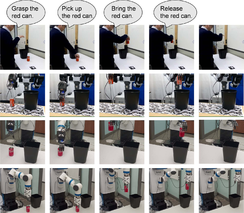
6.3 Throw-away demo
Figure 47 shows the result from the demonstration to the execution of the throw-away demo by the three robots. The task sequence was recognized as Active-force grasp, PC-NC-a (PTG11), NC-NC (PTG12), and Release. The difference between the place-on-plate demo and the throw-away demo is to release an object before placing it. The three robots executed the same task sequence.
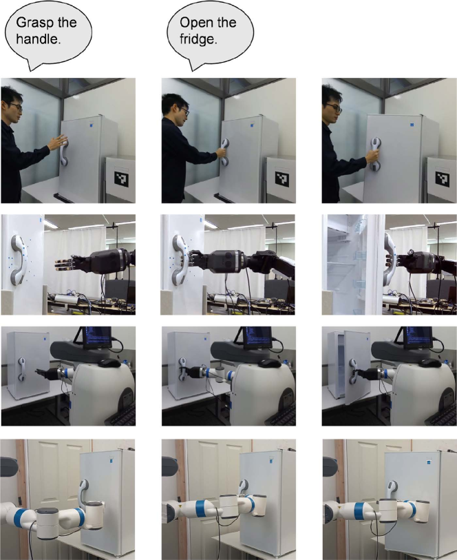
6.4 Open-fridge demo
Figure 48 shows the result from the demonstration to the execution of the open-fridge demo by the three robots. The task sequence was recognized as Lazy-closure grasp and OR-RV (PTG51). All robots succeeded in opening the door.
6.5 Findings from demonstration
6.5.1 How reusable?
Since the hand is the same in Nextage-Shadow and Fetch-Shadow, the implemented skill agents (both manipulation and grasping skill agents) are reusable by changing the IK solver for Nextage or Fetch. Since the hand is different in Fetch-Shadow and Fetch-Parallel, it is necessary to change the grasping skill agents. Fortunately, the parallel gripper has only one DOF, just opening and closing, and thus, the grasping is achieved by positioning the hand and closing. That is not so difficult to implement. Furthermore, the manipulation skill agents can be used as is; the finger joints are fixed in the execution of these skills and the execution is completed by body motion.
Through the experiments, we found the following two things. First, we found that each hardware has a different range of acceptable skill parameters. For example, in the place-on-plate demo, the approach direction of the parallel gripper is changed to the upward to increase the success rate of the task sequence. Conversely, if the acceptable range is known, the success rate can be increased by adjusting the parameters without changing the nature of the target task sequence. Second, we found that it may be better not to use human grasping strategies as they are in the parallel gripper, because the parallel gripper differs significantly from a human hand in the shape and DOF. The OR-RV (PTG51) task can be achieved under satisfying the assumption where a hand and an object are integrated into one unit. Though Fetch-Parallel was able to open the fridge, the excessive feedback may be applied due to the deviation from the assumption at the beginning of the opening. Although Shadow Dexterous Hand Lite can be hooked while wrapping the handle, the parallel gripper touch the handle at small number of contact points.
6.5.2 Comparison to related work
Murali et al. (2019) proposed the open-source Robotic framework, PyRobot, which is aware of hardware independent. The hardware independent is the concept similar to the hardware-level reusability. That target robotic tasks of the framework includes manipulation and navigation. There is the difference in the target users, such as ordinary person in ours and the person who has a programming skill in theirs. In their framework, it is necessary to write a code, such as detecting the grasping point using an RGB image, set a preparation pose and the pose to grasp using the detection results, and send the command to close the hand. Thanks to the framework, each operation can be written by a one-line code, but the user needs to write a several-line code in total. Furthermore, the user needs to consider the mathematics to decide the preparation and grasping poses. When considering such things, it is required to be aware of hardware, such as which approach direction eases grasping. That reduces the hardware-level reusability of the written code.
On the other hand, the target user of the proposed system is an ordinary person, who does not have a programming skill. For such a person, it is desirable to enable to make a program for the place-to-plate demo using the instruction, such as grasping a box and pick it up. That requires the robot system to remove the effort of programming such as use of the vision and mathematics to decide the pose of the gripper. The proposed system provides those using the hint from the human demonstration. Using more abstracted instructions can remove awareness of the hardware. For example, issues related to approach direction in grasping are solved by the system.
7 Summary and discussion
This paper focused on the second step of Learning-from-observation (LfO), emphasizing the portion where the task models, obtained from demonstrations, were executed on the various robots. In line with the spirit of LfO, an effort was made to create a system that is as independent on the robot’s hardware as possible. Attention was directed towards hand motions to design skill agents that move the hand to satisfy conditions derived from the task requirements and physical constraints from the environment. By taking hand motions as a reference, differences in hardware among robots are absorbed into inverse kinematics (IK), allowing the easy substitution of an appropriate IK when hardware changes, ensuring many skill agents can be used.
In environments with physical constraints, adjustments to hand trajectories are often necessary; such a concept is known as compliant manipulation (Mason (1981)). Recently, reinforcement learning (RL) has been applied to address household tasks, including compliant manipulation. However, traditional RL methods have primarily focused on designing policies for specific tasks and requiring individual learning for each new task. We proposed policies that consider constraints applicable to various tasks by grouping multiple tasks based on the types of physical constraints. The type of physical constraints are determined by the characteristics of the imposed force directions. Consequently, a general policy is learned based on these characteristics.
End-to-end generation of robot programs using large language models (LLM) has been proposed in general, such as Vemprala et al. (2023); Wake et al. (2023); Yu et al. (2023). However, many robot tasks require compliant manipulation. In the case of compliant manipulation, adjusting the hand trajectory using force feedback becomes necessary. While systems based on LLMs can provide an overview of program design, generating programs with adjusting capabilities using local feedback is challenging. To address this issue, we proposed preparing a standard set of machine-independent executable skill agents using reinforcement learning or similar methods. This standard set can be provided as a prompt to the LLMs, enabling the design of a robot system that can actually execute. We consider this approach holds promise for resolving the challenge of incorporating local feedback in robot program generation using LLMs.
In this paper, we utilized Shadow Hand on two different robots. As a result, we were able to share the same grasp skill-agent library. In the case of the parallel gripper of Fecth, we resolved the difference in the hardware by only changing the grasp skill-agent library. Standardizing grasp skill agents across different robotic hands remains a challenge for future research.
References
- Akgun et al. (2012) Akgun B, Cakmak M, Jiang K and Thomaz AL (2012) Keyframe-based learning from demonstration: Method and evaluation. International Journal of Social Robotics (IJSR) 4(4): 343–355.
- Ando et al. (2008) Ando N, Suehiro T and Kotoku T (2008) A software platform for component based rt-system development: Openrtm-aist. In: Simulation, Modeling, and Programming for Autonomous Robots. Berlin, Heidelberg: Springer Berlin Heidelberg, pp. 87–98.
- Asfour et al. (2008) Asfour T, Gyarfas F, Azad P and Dillmann R (2008) Imitation learning of dual-arm manipulation tasks in humanoid robots. International Journal of Humanoid Robotics (IJHR) 5(2): 289–308.
- Bachiller-Burgos et al. (2020) Bachiller-Burgos P, Barbecho I, Calderita LV, Bustos P and Manso LJ (2020) Learnblock: A robot-agnostic educational programming tool. IEEE Access 8: 30012–30026. DOI:10.1109/ACCESS.2020.2972410.
- Beeson and Ames (2015) Beeson P and Ames B (2015) Trac-ik: An open-source library for improved solving of generic inverse kinematics. IEEE-RAS International Conference on Humanoid Robots (November): 928–935.
- Billard et al. (2008) Billard A, Calinon S, Dillmann R and Schaal S (2008) Robot programming by demonstration. Springer handbook of robotics : 1371–1394.
- Brooks (1986) Brooks R (1986) A robust layered control system for a mobile robot. IEEE Journal on Robotics and Automation 2(1): 14–23. DOI:10.1109/JRA.1986.1087032.
- Cheng et al. (2018) Cheng CA, Mukadam M, Issac J, Birchfield S, Fox D, Boots B and Ratliff N (2018) RMPflow: A computational graph for automatic motion policy generation. In: The 13th International Workshop on the Algorithmic Foundations of Robotics. URL arXivpreprintarXiv:1811.07049.
- Dellaert et al. (1999) Dellaert F, Fox D, Burgard W and Thrun S (1999) Monte carlo localization for mobile robots. In: Proceedings of (ICRA) International Conference on Robotics and Automation, volume 2. pp. 1322 – 1328.
- Dillmann et al. (2010) Dillmann R, Asfour T, Do M, Jäkel R, Kasper A, Azad P, Ude A, Schmidt-Rohr SR and Lösch M (2010) Advances in robot programming by demonstration. KI-Künstliche Intelligenz 24(4): 295–303.
- Edmonds et al. (2019) Edmonds M, Gao F, Liu H, Xie X, Qi S, Rothrock B, Zhu Y, Wu YN, Lu H and Zhu SC (2019) A tale of two explanations: Enhancing human trust by explaining robot behavior. Science Robotics 4(37): eaay4663. DOI:10.1126/scirobotics.aay4663. URL https://www.science.org/doi/abs/10.1126/scirobotics.aay4663.
- Hogan (1984) Hogan N (1984) Impedance control: An approach to manipulation. In: 1984 American Control Conference. pp. 304–313. DOI:10.23919/ACC.1984.4788393.
- Hutchinson-Guest (1970) Hutchinson-Guest A (1970) Labanotation: The System of Analyzing and Recording Movement. New York: Theatre Arts Books.
- Ikeuchi et al. (2018) Ikeuchi K, Ma Z, Yan Z, Kudoh S and Nakamura M (2018) Describing upper-body motions based on Labanotation for learning-from-observation robots. International Journal of Computer Vision (IJCV) 126(12): 1415–1429.
- Ikeuchi et al. (2021) Ikeuchi K, Wake N, Arakawa R, Sasabuchi K and Takamatsu J (2021) Semantic constraints to represent common sense required in household actions for multi-modal learning-from-observation robot. arXiv preprint arXiv:2103.02201 .
- Jin et al. (2018) Jin L, Li S, Yu J and He J (2018) Robot manipulator control using neural networks: A survey. Neurocomputing 285: 23–34. DOI:https://doi.org/10.1016/j.neucom.2018.01.002.
- Kuhn and Tucker (1957) Kuhn H and Tucker A (1957) Linear inequalities and related systems. Bull. Amer. Math. Soc 63: 202–203.
- Lin et al. (2022) Lin N, Li Y, Tang K, Zhu Y, Zhang X, Wang R, Ji J, Chen X and Zhang X (2022) Manipulation planning from demonstration via goal-conditioned prior action primitive decomposition and alignment. IEEE Robotics and Automation Letters 7(2): 1387–1394. DOI:10.1109/LRA.2021.3140127.
- Mason (1981) Mason MT (1981) Compliance and force control for computer controlled manipulators. IEEE Transactions on Systems, Man, and Cybernetics 11(6): 418–432. DOI:10.1109/TSMC.1981.4308708.
- Moravec and Elfes (1985) Moravec H and Elfes A (1985) High resolution maps from wide angle sonar. In: Proceedings. 1985 IEEE International Conference on Robotics and Automation, volume 2. pp. 116–121. DOI:10.1109/ROBOT.1985.1087316.
- Murali et al. (2019) Murali A, Chen T, Alwala KV, Gandhi D, Pinto L, Gupta S and Gupta A (2019) Pyrobot: An open-source robotics framework for research and benchmarking. arXiv preprint arXiv:1906.08236 .
- Quigley (2009) Quigley M (2009) Ros: an open-source robot operating system. In: IEEE International Conference on Robotics and Automation.
- Roth (1984) Roth B (1984) Screws, motors, and wrenches that cannot be bought in a hardware store. In: Proc. Int. Symp. Robotics Research. pp. 679–693.
- Saito et al. (2022) Saito D, Sasabuchi K, Wake N, Takamatsu J, Koike H and Ikeuchi K (2022) Task-grasping from a demonstrated human strategy. In: 2022 IEEE-RAS 21st International Conference on Humanoid Robots (Humanoids). pp. 880–887. DOI:10.1109/Humanoids53995.2022.10000167.
- Sasabuchi et al. (2021) Sasabuchi K, Wake N and Ikeuchi K (2021) Task-oriented motion mapping on robots of various configuration using body role division. IEEE Robotics and Automation Letters 6(2): 413–420. DOI:10.1109/LRA.2020.3044029.
- Schaal (1999) Schaal S (1999) Is imitation learning the route to humanoid robots? Trends in Cognitive Sciences 3(6): 233–242.
- Schaal et al. (2003) Schaal S, Ijspeert A and Billard A (2003) Computational approaches to motor learning by imitation. Philosophical Transaction of the Royal Society of London: Series B, Biological Sciences 358(1431): 537–547.
- Starke et al. (2017) Starke S, Hendrich N and Zhang J (2017) A memetic evolutionary algorithm for real-time articulated kinematic motion. In: 2017 IEEE Congress on Evolutionary Computation (CEC). IEEE, pp. 2473–2479.
- Vemprala et al. (2023) Vemprala S, Bonatti R, Bucker A and Kapoor A (2023) Chatgpt for robotics: Design principles and model abilities.
- Wake et al. (2021) Wake N, Arakawa R, Yanokura I, Kiyokawa T, Sasabuchi K, Takamatsu J and Ikeuchi K (2021) A learning-from-observation framework: One-shot robot teaching for grasp-manipulation-release household operations. In: 2021 IEEE/SICE International Symposium on System Integration (SII). IEEE, pp. 461–466.
- Wake et al. (2023) Wake N, Kanehira A, Sasabuchi K, Takamatsu J and Ikeuchi K (2023) Chatgpt empowered long-step robot control in various environments: A case application. IEEE Access 1: 95060–95078. Open Access https://doi.org/10.1109/ACCESS.2023.3310935.
- Yu et al. (2023) Yu W, Gileadi N, Fu C, Kirmani S, Lee KH, Arenas MG, Chiang HTL, Erez T, Hasenclever L, Humplik J, Ichter B, Xiao T, Xu P, Zeng A, Zhang T, Heess N, Sadigh D, Tan J, Tassa Y and Xia F (2023) Language to rewards for robotic skill synthesis.
Appendix A Interstate transition details
Analysis of the remaining part of the interstate transition is given here.
A.1 OP-PR and PR-OP
OP-PR
A typical example of an object in OP (M=0, D=1, C=2) is a peg fully inserted into a hole with touching the bottom of the hole. The possible motion of the peg is limited to the motion of pulling it out from the hole. When the peg is slightly pulled out, it detaches from the bottom surface. In other words, the transition occurs from the detachment d-state to the maintenance d-state. A3 is applicable to this direction. Two dimensions orthogonal to the motion direction remain constrained both before and after the transition, requiring control to maintain the constraint d-state throughout the transition, as indicated by B3.
In summary,
  Reward OP-PR (PTG31 (Drawer-open) task)
    if F-t > delta-collision, penalty
    if F-u > delta-collision, penalty
    if F+s < delta-zero AND S = goal-s,
      then reward
PR-OP
An example of a transition from PR (M=1, D=0, C=2) to OP (M=0, D=1, C=2) is inserting a peg partway into a hole until it reaches the bottom of the hole, in contrast to the previous example. Concerning the direction of motion, the transition occurs from the maintenance d-state to the detachment d-state. In other words, A2 is applicable, with the termination condition being the onset of the drag force. The two dimensions orthogonal to the motion constrained by the environment both before and after the transition. B3 is applicable, necessitating control to maintain the constraint d-state throughout the transition.
In summary,
  Reward PR-OP (PTG33 (Drawer-close) task)
    if F-t > delta-collision, penalty
    if F-u > delta-collision, penalty
    if F-s > delta-zero, reward
A.2 PR-NC and NC-PR
PR-NC
An example of a transition from PR (M=1, D=0, C=2) to NC (M=3, D=0, C=0) involves a peg partially inserted into a hole suddenly popping out of the hole. Concerning the direction of motion, it remains in the maintenance d-state before and after the transition. In other words, A1 is applicable, and the terminal condition can be defined solely based on positional information, given by the demonstration. Regarding the directions orthogonal to the motion, both directions are constrained before the transition and the constraints from the environment are lifted, entering the maintenance d-state after the transition. B8 is applicable.
In summary,
  Reward PR-NC
    if F-t > delta-collision, then penalty
    if F-u > delta-collision, then penalty
    if S = goal-s AND F-t < delta-zero AND
       T = goal-t AND F-u < delta-zero AND
       U = goal-u, then reward
NC-PR
The transition from NC (M=3, D=0, C=0) to PR (M=1, D=0, C=2) corresponds to the opposite scenario of the previous example, where a peg in the air is suddenly inserted into a hole. Concerning the direction of motion, the maintenance d-state is maintained. In other words, A1 is applicable, and the terminal condition is defined solely based on positional information, given by the demonstration. Regarding the directions orthogonal to the motion, both directions are unconstrained before the transition, and after the transition, they transit into the constrained d-state due to environmental constraints. Specifically, B9 is applicable, indicating that visual feedback in those dimensions is necessary.
In summary,
  Reward NC-PR
    if NOT(AfterTransition):
      if |T - feature-t| > delta-gap,
        then penalty
      if |U - feature-u| > delta-gap,
        then penalty
    else:
      if F-t > delta-collision, then penalty
      if F-u > delta-collision, then penalty
      if S = goal-s, then reward
A.3 PR-PC and PC-PR
PR-PC
An example of a transition from PR (M=1, D=0, C=2) to PC (M=2, D=1, C=0) involves pulling a peg out from within a hole. As the peg moves, one direction orthogonal to the motion direction maintains contact with the continuous surface even after leaving the hole, while the other direction becomes unconstrained and enters the maintenance d-state. In this case, the detachment d-state occurs in one direction (with the bottom surface), and the maintenance d-state is reached in the other.
Concerning the direction of motion, it remains in the maintenance d-state, making A1 applicable. On the other hand, in dimensions orthogonal to the motion, for one dimension, there is a transition from the constraint d-state to the maintenance d-state (B8 is applicable), and for the other dimension, there is a transition from the constraint d-state to the detachment d-state (B7 is applicable).
In summary,
   Reward PR-PC
    if F-t > delta-collision, then penalty
    if F-u > delta-collision, then penalty
    if F-u < delta-zero, then penalty
    if S = goal-s AND F-t < delta-zero AND
       T = goal-t, then reward
PC-PR
In the transition from PC (M=2, D=1, C=0) to PR (M=1, D=0, C=2), for one dimension orthogonal to the direction of motion, the maintenance d-state transits to the constraint d-state, while in the other dimension, the detachment d-state transits to the constraint d-state. This scenario could be exemplified by sliding a peg on a table, causing the peg into a hole and all faces of the peg become constrained.
The direction of motion, both before and after the transition, maintains the maintenance d-state, making A1 applicable. In one dimension orthogonal to the motion, where the detachment d-state transits to the constraint d-state, B6 is applicable. Namely, by maintaining the detachment d-state, the system automatically enters the constraint d-state. For the other dimension, the transition from the maintenance d-state to the constraint d-state occurs and B9 is applicable, indicating the need for visual feedback.
In summary,
  Reward PC-PR
    if F-t > delta-collision, then penalty
    if F-t < delta-zero, then penalty
    if NOT(AfterTransition) AND
       |U - feature-u| > delta-gap,
      then penalty
    if AfterTransition AND
       F-u > delta-collision, then penalty
    if S = goal-s, then reward
A.4 PR-TR and TR-PR
PR-TR
The transition from PR (M=1, D=0, C=2) to TR (M=2, D=0, C=1) involves a scenario where, upon pulling the peg out of the hole, constraints in the one direction of the hole remains. In terms of the direction of motion, it remains in the maintenance d-state, and A1 is applicable. For one dimension orthogonal to the direction of motion, the constraint d-state transits to the maintenance d-state, making B8 applicable. For the other dimension, the constraint d-state is maintained, so B3 is applicable:
In summary,
  Reward PR-TR
    if F-t > delta-collision, then penalty
    if F-u > delta-collision, then penalty
    if S = goal-s AND F-t < delta-zero AND
       T = goal-t, then reward
TR-PR
The transition from TR (M=2, D=0, C=1) to PR (M=1, D=0, C=2) maintains the maintenance d-state in the direction of motion, and A1 can be applied. For one dimension orthogonal to the direction of motion, there is a transition from the maintenance d-state to the constraint d-state, requiring visual feedback. In other words, B9 is applicable. For the other dimension, it remains to be in the constraint d-state, and B3 can be applied.
In summary,
  Reward TR-PR
    if F-u > delta-collision, then penalty
    if NOT(AfterTransition) AND
       |T - feature-t| > delta-gap,
      then penalty
    if AfterTransition AND
       F-t > delta-collision, then penalty
    if S = goal-s, then reward
A.5 PR-OT and OT-PR
PR-OT
The transition from PR (M=1, D=0, C=2) to OT (M=1, D=1, C=1) involves the transition from the constraint d-state to the detachment d-state in one of the two constraint d-state dimensions. For example, when a peg in a hole is pulled out, a portion of one set of opposing constraint surfaces is removed, resulting in a detachment d-state, while the other dimension remains in a constraint d-state.
Regarding the direction of motion, it remains in the maintenance d-state, and A1 can be applied. As for the second dimension to maintain the constraint d-state, B3 can be applied. The third dimension transits from the constraint d-state to the detachment d-state and B7 can be applied.
In summary,
  Reward PR-OT
    if F-t > delta-collision, then penalty
    if F-u > delta-collision, then penalty
    if F-u < delta-zero, then penalty
    if S = goal-s, then reward
OT-PR
The transition from OT (M=1, D=1, C=1) to PR (M=1, D=0, C=2) involves the dimension that was in the detachment d-state transiting to the constraint d-state. For this dimension, maintaining contact alone is sufficient to naturally transit from the detachment d-state to the constraint d-state.
As for the direction of motion, the maintenance d-state remains throughout the transition and A1 can be applied. One dimension orthogonal to the motion remains in the constraint d-state and B3 can be applied. In the other orthogonal dimension to the motion, a transition occurs from the detachment d-state to the constraint d-state. B6 is applicable.
Summarizing these, we obtain:
  Reward OT-PR
    if F-t > delta-collision, then penalty
    if F-u > delta-collision, then penalty
    if F-u < delta-zero, then penalty
    if S = goal-s, then reward
A.6 OT-NC and NC-OT
OT-NC
The transition from OT (M=1, D=1, C=1) to NC (M=3, D=0, C=0) occurs due to the shape of the environment while moving in the maintenance direction rather than the detachment direction. See Figure 49 (a).
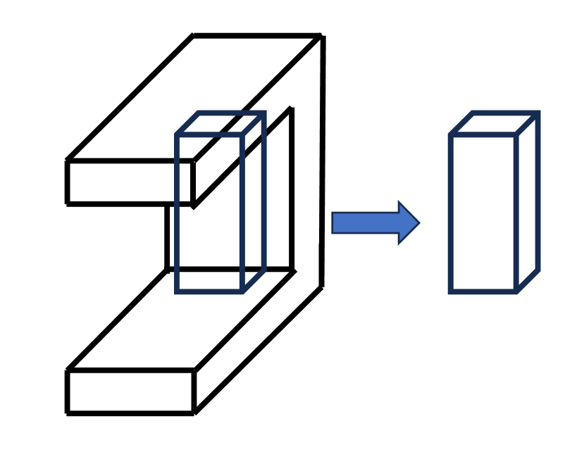
|
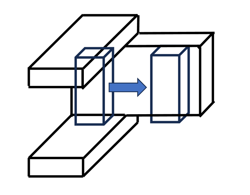
|
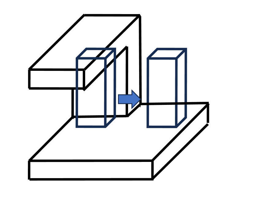
|
|---|---|---|
| (a) | (b) | (c) |
In such case, concerning the direction of motion, the maintenance d-state is maintained. Therefore A1 can be applied. In one dimension orthogonal to the motion, a transition occurs from the detachment d-state to the maintenance d-state. Therefore, B5 can be applied. In the other orthogonal dimension to the motion, the constraint d-state transits to the maintenance d-state. Therefore, B8 is applicable.
In summary,
  Reward OT-NC
    if F-u > delta-collision, then penalty
    if NOT(AfterTransition):
      if F-t > delta-collision, then penalty
      if F-t < delta-zero, then penalty
    else:
      if S = goal-s AND F-t < delta-zero AND
         T = goal-t AND F-u < delta-zero AND
         U = goal-u, then reward
NC-OT
In contrast to the previous scenario, a transition occurs where a peg enters a hook-shaped hole that is partially open in mid-air. In two dimensions orthogonal to the motion, both the detachment d-state and the constraint d-state occur simultaneously from the maintenance d-state.
As for the motion direction, the maintenance d-state is maintained, and A1 can be applied. In one dimension orthogonal to the motion, there is a transition from the maintenance d-state to the detachment d-state and B4 can be applied; a visual sensor is required for this transition. In the other dimension orthogonal to the motion, there is a transition from the maintenance d-state to the constraint d-state and B9 can be applied. This also requires a visual sensor.
In summary,
  Reward NC-OT
    if NOT(AfterTransiton):
      if |T - feature-t| > delta-gap,
        then penalty
      if |U - feature-u| > delta-gap,
        then penalty
    else:
      if F-t > delta-collision, then penalty
      if F-t < delta-zero, then penalty
      if F-u > delta-collision, then penalty
      if S = goal-s, then reward
A.7 OT-PC and PC-OT
The transition from OT (M=1, D=1, C=1) to PC (M=2, D=1, C=0) can occur in two cases: one where the detachment surface remains in contact while the constraint surfaces disappear, as shown in Figure 49 (b), and the other where a portion of constraint surfaces disappear, leading to a detachment state in this dimension, as shown in Figure 49 (c).
OT-PC-a: the detachment surface remains in contact
Regarding the direction of motion, the maintenance d-state is maintained. Therefore A1 can be applied. In one dimension orthogonal to the motion, the detachment d-state is maintained. Therefore B2 can be applied. In the other orthogonal dimension, the constraint d-state transits to the maintenance d-state. Therefore B8 can be applied.
In summary,
  Reward OT-PC-a
    if F-t > delta-collision, then penalty
    if F-t < delta-zero, then penalty
    if F-u > delta-collision, then penalty
    if S = goal-s AND F-u < delta-zero AND
       U = goal-u, then reward
OT-PC-b: a portion of a constraint surface transits to a detachment surface
Regarding the direction of motion, the maintenance d-state is maintained and A1 can be applied. In one dimension orthogonal to the motion, the detachment d-state transits to the maintenance d-state and B5 can be applied. In the other dimension, the constraint d-state transits to the detachment d-state. Therefore B7 is applicable.
In summary,
  Reward OT-PC-b
    if F-u > delta-collision, then penalty
    if F-u < delta-zero, then penalty
    if NOT(AfterTransition):
        if F-t > delta-collision,
          then penalty
        if F-t < delta-zero, then penalty
    else:
      if S = goal-s AND F-t < delta-zero AND
         T = goal-t, then reward
PC-OT-a: the detachment surface remains in contact
As for the transition from PC (M=2, D=1, C=0) to OT (M=1, D=1, C=1), there are also two scenarios. In the PC-OT-a case, regarding to the direction of motion, the maintenance d-state is maintained. A1 can be applied. In one orthogonal direction to the motion, the detachment d-state is maintained. B2 can be applied. In the other orthogonal direction, the maintenance d-state transits to the constraint d-state and B9 can be applied.
In summary,
  Reward PC-OT-a
    if F-t > delta-collision, then penalty
    if F-t < delta-zero, then penalty
    if NOT(AfterTransition) AND
       |U - feature-u| > delta-gap,
      then penalty
    if AfterTransition AND
       F-u > delta-collision, then penalty
    if S = goal-s, then reward
PC-OT-b: the detachment d-state transits to the constraint d-state
Regarding to the motion direction, the maintenance d-state is maintained and A1 can be applied. In one orthogonal dimension to the motion, the maintenance d-state transits to the detachment d-state and B4 can be applied. In the other orthogonal dimension to the motion, the detachment d-state transits to the constraint d-state and B6 can be applied.
In summary,
  Reward PC-OT-b
    if F-u > delta-collision, then penalty
    if F-u < delta-zero, then penalty
    if NOT(AfterTransition):
      if |T- feature-t| > delt-gap,
        then penalty
    else:
      if F-t > delta-collision, then penalty
      if F-t < delta-zero, then penalty
      if S = goal-s, then reward
A.8 OT-TR and TR-OT
The transition from OT (M=1, D=1, C=1) to TR (M=2, D=0, C=1) also occurs through motion in two directions: motion in the detachment direction and motion along the detachment surface.
OT-TR-a: motion in the detachment direction
In the motion direction, the detachment d-state transits to the maintenance d-state. A3 can be applied. In one orthogonal dimension, the maintenance d-state is maintained and B1 can be applied. In the other orthogonal direction, the constraint d-state is maintained and B3 can be applied.
In summary,
  Reward OT-TR-a
    if F-u > delta-collision, then penalty
    if F+s < delta-zero AND S = goal-s AND
       T = goal-t, then reward
OT-TR-b motion along the detachment surface
In the direction of motion, the maintenance d-state is maintained. A1 can be applied. In one orthogonal direction to the motion, the constraint d-state is maintained. B3 can be applied. In the other orthogonal dimension, the detachment d-state transits to the maintenance d-state. B5 can be applied.
In summary,
  Reward OT-TR-b
    if F-t > delta-collision, then penalty
    if NOT(AfterTransition):
      if F-u > delta-collision, then penalty
      if F-u < delta-zero, then penalty
    else:
      if S = goal-s AND F-u < delta-zero AND
         U = goal-u, then reward
TR-OT-a motion toward the detachment surface
The transition from TR (M=2, D=0, C=1) to OT (M=1, D=1, C=1) also occurs in two scenario. In TR-OT-a case, along the motion direction, the maintenance d-state transits to the detachment d-state. A2 can be applied. In one orthogonal dimension, the maintenance d-state is maintained. B1 can be applied. In the other orthogonal dimension, the constraint d-state is maintained. B3 can be applied.
In summary,
  Reward TR-OT-a
    if F-u > delta-collision, then penalty
    if F-s > delta-zero AND T = goal-t,
      then reward
TR-OT-b motion along the detachment surface
In the direction of motion, the maintenance d-state is maintained. A1 can be applied. In one orthogonal direction, the constraint d-state is maintained. B3 can be applied. In the other orthogonal direction, the maintenance d-state transits to the detachment d-state. B4 can be applied.
In summary,
  Reward TR-OT-b
    if F-t > delta-collision, then penalty
    if NOT(AfterTransition):
      if |U - feature-u| > delta-gap,
        then penalty
    else:
      if F-u > delta-collision, then penalty
      if F-u < delta-zero, then penalty
      if S = goal-s, then reward
Appendix B Intrastate transition details
B.1 TR-TR
Regarding the transition from TR (M=2, D=0, C=1) to TR, in the direction of motion, the maintenance d-state is maintained. A1 can be applied. In one orthogonal direction to the motion, the maintenance d-state is maintained. B1 can be applied. In the other orthogonal direction, the constraint d-state is maintained. B3 can be applied.
In summary,
  Reward TR-TR
    if F-u > delta-collision, then penalty
    if S = goal-s AND T = goal-t,
      then reward
B.2 OT-OT
The OT state consists of a set of two Kuhn-Tucker solution classes. OT1 (M=1, D=1, C=1) has the solution domain on a semi-circular arc on the great circle, while OT2 (M=0, D=2, C=1) has a partial arc of the great circle as the domain of solutions.
OT1-OT1
In OT1, there are two possible directions of motion: motion in the detachment direction and motion along the detachment surface. However, to transit to OT1, motion along the detachment surface is required. In this case, the d-state of motion direction is such that the maintenance d-state is preserved. A1 can be applied. On the other hand, in one orthogonal direction to the motion, the detachment d-state is maintained. B2 can be applied. In the other orthogonal dimension, the constraint d-state is maintained. B3 can be applied.
In summary,
  Reward OT1-OT1
    if F-t > delta-collision, then penalty
    if F-t < delta-zero, then penalty
    if F-u > delta-collision, then penalty
    if S = goal-s, then reward
OT1-OT2
The region of solutions for OT1, with further constraints, becomes a partial arc, resulting in OT2. Therefore, the transition from OT1 (M=1, D=1, C=1) to OT2 (M=0, D=2, C=1) occurs in cases where motion along the detachment surface results in encountering another contact surface. Consequently, concerning the direction of motion, the maintenance d-state transits to the detachment d-state. A2 can be applied. One orthogonal direction to the motion maintains the detachment d-state. B2 can be applied. The other orthogonal direction to the motion maintains the constraint d-state. B3 can be applied.
In summary,
  Reward OT1-OT2
    if F-t > delta-collision, then penalty
    if F-t < delta-zero, then penalty
    if F-u > delta-collision, then penalty
    if F-s > delta-zero, then reward
OT2-OT1
The transition from OT2 (M=0, D=2, C=1) to OT1 (M=1, D=1, C=1) is the reverse of the previous transition, where the solution domain restricted to a partial arc, transits through detachment motion to a semi-circle region. Therefore, concerning the direction of motion, a transition from the detachment d-state to a maintenance d-state occurs. Therefore A3 can be applied. One orthogonal direction to the motion maintains the detachment d-state. B2 can be applied. The other orthogonal direction to the motion maintains the constraint d-state. B3 can be applied.
In summary,
  Reward OT2-OT1
    if F-t > delta-collision, then penalty
    if F-t < delta-zero, then penalty
    if F-u > delta-collision, then penalty
    if F+s < delta-zero AND S = goal-s,
      then reward