phloSAR: a Portable, High-Flow Pressure Supply and Regulator Enabling Untethered Operation of Large Pneumatic Soft Robots
Abstract
Pneumatic actuation benefits soft robotics by facilitating compliance, enabling large volume change, and concentrating actuator weight away from the end-effector. However, portability is compromised when pneumatic actuators are tethered to cumbersome air and power supplies. While there are existing options for portable pneumatic systems, they are limited in dynamic capabilities, constraining their applicability to low pressure and/or small-volume soft robots. In this work, we propose a portable, high-flow pressure supply and regulator (phloSAR) for use in untethered, weight-constrained, dynamic soft robot applications. PhloSAR leverages high-flow proportional valves, an integrated pressure reservoir, and Venturi vacuum generation to achieve portability and dynamic performance. We present a set of models that describe the system dynamics, experimentally validate them on physical hardware, and discuss the influence of design parameters on system operation. Lastly, we integrate a proof-of-concept prototype with a soft robot arm mounted on an aerial vehicle to demonstrate the system’s applicability to mobile robotics. Our system enables new opportunities in mobile soft robotics by making untethered pneumatic supply and regulation available to a wider range of soft robots.
I Introduction
Soft robots exhibit passive adaptation to their environment, enabling inherent safety and robustness. Pneumatic actuation is a common choice for soft robots as it facilitates compliance and large volume change while relocating actuator mass away from the end-effector. However, pneumatic soft robots (PSRs) require a method for pressure generation and regulation, and many of these robots rely on pneumatic tubing that tethers them to heavy air compressors [1]. Meanwhile, untethered PSRs leverage methods such as micro pumps [2, 3, 4, 5, 6], syringe displacement systems [7], CO2 gas cartridges [8, 9], and chemical reactions [10]. However, these untethered solutions are intended for PSRs with smaller volumes or low-flow requirements. While untethered pneumatic solutions exist for larger PSRs [11, 12], this comes at the cost of added size and weight, limiting their suitability in PSR applications with stringent payload limits (e.g., soft aerial manipulation).
In this work, we address the limitations of existing solutions regarding performance and portability with a portable, high-flow, pressure supply and regulator (phloSAR). It leverages high-flow pneumatic components for high-speed pressure regulation of large volumes, and it integrates a refillable high-pressure air reservoir that enables untethered operation of PSRs. This work provides the following contributions:
-
1.
The design details of phloSAR, which uses high-flow proportional valves, an integrated pressure reservoir, and Venturi vacuum generation, enabling untethered operation of large-volume pneumatic soft robots.
-
2.
Models, verification, and guidelines that aid in the design of future phloSARs for custom applications.
-
3.
Implementation of a physical phloSAR prototype and a demonstration on a mobile soft robot.
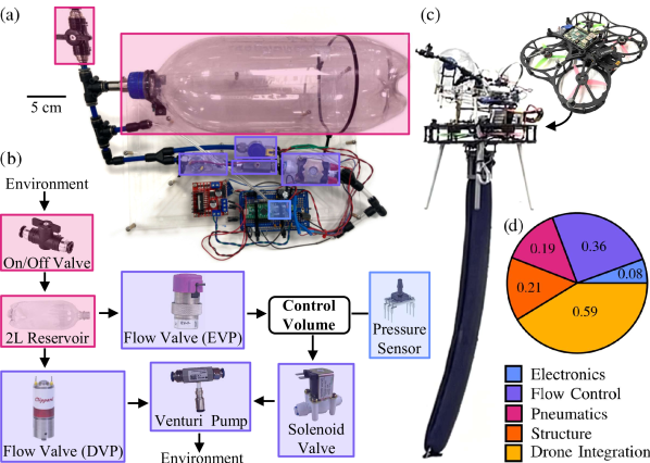
This work aims to be a design guide to aid in implementing a phloSAR given a specific mobile PSR. As a motivating example, the phloSAR implemented in this work was customized for an inflated-beam “vine” robot [17]. These continuum robots grow in length via tip eversion and often feature pneumatic actuation for bending [18]. Traditional vine robots operate from a base fixed in the environment and require pneumatic tethering to heavy air compressors [14, 19]. In this work, we demonstrate that a vine robot with a phloSAR is portable enough to operate onboard an aerial vehicle, opening applications in aerial manipulation not previously feasible for this class of soft robot (Fig. 1).
II Design Considerations and Prior Work
When considering pneumatic solutions for mobile soft robots, three key design factors are its form, dynamic performance, and amenability to untethered operation. For form, we consider cost, weight, size, and customizability. For dynamic performance, we consider speed of pressure change and the output pressure range and resolution. For amenability to untethered operation, we consider whether the solution incorporates a portable pressure source, and whether the choice of air supply impacts system redeployment or operation duration (which we term “renewability”). An overview can be seen in Fig 2.
These design choices are inter-dependent, and the specific balance of requirements will be informed by the PSR for which the pneumatic system is intended.
II-A Dynamic Performance Considerations
A pneumatic soft robot or actuator can be considered as a sealed volume requiring pressure regulation; this paper uses the general term “control volume” (CV). To understand the dynamics of pressurizing an arbitrary control volume, we consider the ideal gas law in its derivative form:
| (1) |
where is the rate of pressure increase of the CV, is the standard volumetric flow rate into the CV, is the universal gas constant, is the number of gas moles in the CV, and , , , are the density, temperature, and molar mass of air at standard conditions, respectively. From this relationship, we see that high-speed CV pressurization requires a high-flow (high ) regulator. To understand the factors that determine flow rate, we consider Ohm’s Law of fluid flow:
| (2) |
where is pressure difference across a valve and is the effective flow resistance across a valve (units can be derived from dimensional analysis). In the context of pressure supply and regulation, a pneumatic system with strong dynamic performance features a large pressure difference between the pressure supply and CV () and operates with a small flow resistance ().
II-B Untethered Pressure Sources
Untethered operation of a PSR is typically dependent on having a portable pressure source. The two main options for this are (1) devices that generate airflow, and (2) pressure reservoirs.
A common device for generating airflow for untethered PSRs is a micropump [2, 3, 4, 5, 6, 12]. These devices exist in small, lightweight form factors and can continuously supply pressure as long as they have battery power. However, their flow rate drops as pressure accumulates at the outlet, and they have limited maximum flow rates up to approximately 10 standard liters per minute (SLPM). While these limitations do not preclude small-volume PSR applications, they are impractical for large-volume, high-speed PSR applications. A second option for generating airflow are syringe methods [7], which similarly suffer from limited flow rates in addition to having a small total capacity.
Air reservoirs can achieve higher pressure gradients but inherently have a limited operable duration. For a fixed mass of air, choosing a reservoir involves a tradeoff between the size, weight, and reservoir pressure. Single-use CO2 cartridges are compact options that contain pressures up to approximately 6000 kPa [8, 9]. However, this comes with practical challenges such as having to manually replace the canister after each use, sourcing components for the regulator that can withstand such a high inlet pressure, and preventing regulator “freeze up”. A lower-pressure or smaller reservoir can be made viable by incorporating a portable air compressor [11] that refills the reservoir, but using a compressor increases system weight, size, and cost, and using a lower-pressure reservoir reduces dynamic performance.
The phloSAR strikes a balance between these methods. It features an air reservoir at a moderate pressure (690 kPa), which facilitates dynamic performance while offering enough capacity to eliminate the need for an onboard compressor.
II-C Methods for Pressure Regulation
Off-the-shelf pressure regulators make different trade-offs in performance, portability, and cost. An off-the-shelf regulator reduces complexity by handling feedback control internally, but requires a pressure source that satisfies the inlet specifications of the regulator.
Alternatively, a pressure regulator can be custom-built by leveraging closed-loop control of flow valve arrays (binary solenoid valves and/or proportional valves) to achieve pressure regulation. This is a common strategy in existing untethered pneumatic systems [2, 3, 4, 5, 6, 15, 11]. Building a custom regulator with flow valves provides flexibility in that the designer selects regulator components jointly with the pressure source. Additionally, flow valves tend to be less bulky, heavy, and expensive than off-the-shelf pressure regulators, and they can operate at higher inlet pressures, making them amenable to use with high-pressure air supplies.
PhloSAR implements pressure regulation via flow control but is intended for dynamic operation of large-volume PSRs, which have higher flow requirements than many of the systems in prior works.
III Design and Implementation
We discuss design decisions for implementing a phloSAR for a specific PSR, but the design is highly customizable in that components can be readily swapped to achieve different performance specifications as needed.
III-A Flow Modulation
Airflow in and out of the CV is modulated with proportional valves that have an affine relationship between flow and input current (Clippard “EVP” EC-P-05-25-A0 and “DVP” DV-PM-10-670100-V). The use of proportional valves, and the Clippard valves in particular, offers several benefits. First, they offer large maximum flow rates (EVP: 23.5 SLPM; DVP: 67.0 SLPM), which enables dynamic performance. Second, they allow the use of high inlet pressures (up to 690 kPa for the chosen valves). This allows the use of high-pressure reservoirs that are directly connected to the valve inlet, eliminating the need for intermediate components that would add weight and design complexity. Third, they are small and lightweight (EVP: 52 mm, 77 g; DVP: 64 mm, 139 g), which is critical for portability.
III-B Pressure Reservoir
A high-pressure air reservoir allows for higher flow rates (Eq. 2) and a longer operation time due to the increased amount of air stored (ideal gas law). Larger reservoirs similarly allow longer operations times but there exists a trade off between portability and operation time. In the implemented prototype, we use a 2-liter bottle made from polyethylene terephthalate (PET). This reservoir choice is lightweight (70 g), low-cost ($1), and readily available (e.g. 2L soda bottle), and can withstand pressures over 900 kPa. We integrate a pneumatic fitting with the reservoir cap for routing tubing to the flow valves and to a manual on/off valve for refilling. The reservoir is easily refilled by opening the on/off valve and supplying compressed air. While it is the largest component of the implemented prototype (30 cm long), the large volume allows for more storage capacity.
III-C Vacuum Source
Passive venting to atmosphere or the use of vacuum pumps are simple solutions for decreasing CV pressure, but they suffer from limited pressure gradients and flow rates that reduce dynamic performance. Instead, the phloSAR design generates a vacuum with a Venturi pump (Coval VR09f14) that enables higher flow rates out of the CV. A Venturi pump is also advantageous in that it is pneumatically driven by the same pressure reservoir used for inflation. Specifically, high-velocity flow through the Venturi pump, from the inlet to the exhaust port, generates vacuum at a third port. This Venturi effect is used to actively draw air from CV, which is also released through the exhaust port.
III-D Operation and Controls
The phloSAR controller coordinates commands to multiple valves to modulate airflow for CV pressure regulation. The first valve, the EVP, modulates flow from the reservoir into the CV. The second valve, the DVP, modulates flow from the reservoir into the Venturi pump. The third valve, a binary solenoid valve (Shenzhen Huamei Technology Co.), enables flow out of the CV and into the vacuum port of the Venturi pump. During inflation, the phloSAR modulates flow into the CV by actuating the EVP, and during deflation, the phloSAR modulates flow out of the CV by coordinating actuation of the DVP and solenoid valve. Actuating the solenoid valve alone allows passive venting from the CV, and actuating the DVP in tandem enables active deflation.
The valves are actuated with an L298N motor driver with commands from a Teensy LC microcontroller. The microcontroller uses pressure feedback from the CV and pressure reservoir (Honeywell pressure sensors ABPDANN030PGAA5 and ABPDANN015BGAA5) to determine the appropriate command. For low tracking errors, we use a PID controller. For high tracking errors, an on-off controller sends commands to maximize flow rate. The tracking error cutoff used to select between the two controllers (1 kPa) was determined empirically. During deflation, the phloSAR selects between passive venting and active deflation, only leveraging active deflation when additional speed is required. This improves air-use efficiency.
IV System Dynamics
While we implement one example phloSAR, the design is highly customizable and intended to be adapted for other mobile PSRs. Here we provide models of system dynamics that give insight into phloSAR performance that can be used for designing other implementations of phloSAR.
IV-A Pressure Reservoir Discharge
Under constant operation, a pressure reservoir has a finite operation time before depletion. We provide a simple model based on the ideal gas law and Ohm’s fluid law in Eq. 2 to capture reservoir pressure over time:
| (3) |
where and . is the initial pressure, is the reservoir volume, and is the flow resistance across the reservoir outlet valve. The model assumes the reservoir is discharging to atmosphere through a valve with constant flow resistance. In practice, the reservoir discharges to a CV, which is typically at a higher pressure than atmosphere, and the flow resistance can be modulated, but this model can be used to provide a conservative estimate of operation time by setting the model resistance to the minimum value for the implemented phloSAR. This model is also conservative because during real operation reservoir discharge halts when CV pressure stabilizes around the commanded pressure. In addition, reservoir discharge during CV deflation is more efficient than CV inflation because the phloSAR leverages both passive venting and active deflation, so the air discharged as motive fluid for the Venturi pump is, on average, less than the air vented from the CV.
IV-B Inflation Speed
The time-rate at which the CV’s pressure can be changed serves as a benchmark for the dynamic performance of a particular phloSAR setup. Assuming a high-pressure reservoir relative to the CV (), we derive the following from Eq. 1 and 2:
| (4) |
This model is intended to aid in component selection for a phloSAR implementation. The size of the control volume depends on the PSR application, but the reservoir pressure () and flow resistance () can be adjusted based on the choice of reservoir and proportional valve by the designer. decreases as the reservoir is depleted; we provide addition discussion in Sec. VI-B.
IV-C Frequency Response
To model phloSAR frequency response, we consider a sinusoidal command and compute the maximum derivative:
| (5) |
where is the command amplitude and is a constant offset. For a phloSAR with a maximum inflation speed, , larger than , the phloSAR tracks the command with unity gain. If is less than , we make a simplifying assumption that the phloSAR exhibits sinusoidal behavior with a maximum slope . This can be used to solve for the output gain. This yields the following model for the phloSAR frequency response and cutoff frequency :
| (6) |
| (7) |
This model shows that phloSAR bandwidth is affected by its PSR application. Specifically, is influenced by the magnitudes of pressure required by the PSR, and depends on the CV and phloSAR setup used (Eq. 4).
V Experimental Verification
Here we verify each model presented in Sec. IV.
V-A Pressure Reservoir Discharge Verification
Equation 3 is verified with discharge tests that use the following procedure: fill a reservoir to an initial pressure, open an outlet valve at constant flow resistance, and monitor the reservoir pressure () over time. We performed discharge tests with varied initial reservoir pressure (), reservoir volumes (), and flow resistances (), and compared the measured and modeled pressures over time with the nRMSE shown in Fig. 3. The nRMSE for the displayed tests are in the range 4.1-5.7% (normalized with respect to ), which suggests that reservoir discharge is captured well by Eq. 3.
V-B Inflation Speed Verification
We verify Eq 4 by analyzing the step response of the phloSAR prototype. We model the response as a piece-wise linear function, in which the pressure increases linearly according to Eq. 4 and then remains constant after reaching the target pressure. We collect experimental data for 3 different test conditions (TC) to show varying inflation speeds:
-
TC1:
= 69 kPa, = 0.5 L, = 689 kPa
-
TC2:
= 34 kPa, = 1 L, = 689 kPa
-
TC3:
= 21 kPa, = 1 L, = 345 kPa
The CVs used were rigid containers.
From Fig. 4, we see that a piecewise linear function for the phloSAR step response captures the behavior well. The nRMSE between the measured and modeled time series, normalized by the commanded pressure, is 2.3%, 10.9%, and 12.9%, for TC1, TC2, and TC3 respectively. For each test, we also compute the average rate of pressure increase and compare it to the rate of change given by Eq. 4. The normalized errors for the three tests, normalized by the model speed, are 0.24%, 44.8%, and 45.0%, for TC1, TC2, and TC3 respectively. In future work, we will explore what causes deviation from the model for larger control volumes. We also note the prioritization of inflation speed, which sometimes caused overshoot (e.g. TC1). We anticipate this could be resolved with further controller design and tuning.
V-C Frequency Response Verification
We verify Eq. 6 by analyzing the phloSAR’s pressure output in response to sinusoidal pressure commands with offset such that kPa (Fig. 5). We consider two test conditions, one with expected operating conditions (TC4) and a second with more extreme conditions (TC5), specifically, a higher amplitude pressure command, larger CV, and lower pressure reservoir:
-
TC4:
= 21 kPa, = 0.5 L, = 689 kPa
-
TC5:
= 34 kPa, = 1 L, = 345 kPa
For each condition, we measure the phloSAR response for a wide range of command frequencies. To compute the gain for a given trial, a Fast Fourier Transform (FFT) is applied to the phloSAR’s pressure time response, and the magnitude at the command frequency is isolated. We used a fixed pressure source of 690 kPa to eliminate the effect of changing on frequency response.
We compare the measured frequency response to the model from Eq. 6, using a measured value for . Both test conditions show qualitative agreement between the modeled and measured frequency response. Although the roll-off rate deviates from the model for the highest frequencies ranges, this is beyond the intended operating bandwidth as these frequencies are much higher than the cutoff frequency. The modeled and measured cutoff frequency for TC4 is 1.35 and 1.6 Hz, respectively, and the modeled and measured cutoff frequency for TC5 is 0.32 and 0.22 Hz, respectively.
Figure 5 also provides a qualitative “baseline” comparison with one of the off-the-shelf regulators from Fig. 2 (Proportion Air QB3TANKKZP6PSG) commonly used to actuate vine robots [14, 20]. However, the baseline regulator is not suited for untethered operation because it does not have an integrated pressure source. Baseline 1 and 2 correspond to TC4 and TC5, except the parameter for reservoir pressure is not applicable. Instead, the baseline regulator is supplied with its maximum recommended inlet pressure. The phloSAR has better performance than the baseline at expected operating conditions (TC4) and worse performance at more extreme conditions (TC5); this is expected when operating outside intended conditions.
Figure 6 provides time-cropped segments from trials with a 1.2 Hz pressure command to visualize the difference in performance for a phloSAR and the baseline regulator. We also overlay the response of a phloSAR with low reservoir pressure to show behavior when operating outside of intended conditions. The peak-to-peak measure of the command is 34 kPa, and the approximate peak-to-peak measure of the phloSAR, low phloSAR, and baseline is 32, 20, and 6 kPa, respectively. This demonstrates the higher dynamic performance of the phloSAR compared to the baseline. As a result, phloSAR exhibits the best tracking performance, although when the reservoir pressure is too low (Low ), the inflation speed is not high enough to track the command. The baseline suffers from slow response times and low inflation speeds leading to poor tracking performance.
VI Influence of Design Parameters on System Operation
Here we synthesize findings from our work to serve as a guideline when implementing a phloSAR.
VI-A Designing for Performance
The high-level insights from Secs. IV-B and IV-C are that maximizing phloSAR dynamic ability can be achieved through:
-
1.
Maximizing starting reservoir pressure ()
-
2.
Minimizing minimum flow resistance () when sourcing proportional flow valves
-
3.
Minimizing volume () and pressure difference between “on” and “off” states () of the CV (e.g. PSR actuators).
However, this needs to be considered jointly with cost, size, and weight considerations of the phloSAR, and performance requirements of the PSR.
VI-B Designing for Operation Duration
The discharge model in Sec. IV-A gives a sense of operable duration, and we supplement this with a metric for the number of CV inflation-deflation cycles () that can be achieved for a given phloSAR and setup.
Given a target inflation speed, , and the change in pressure during inflation, , there is a minimum reservoir pressure for the phloSAR to satisfy the target inflation speed (Eq. 4). For a specific reservoir volume and initial pressure, we can compute the quantity of air that can be supplied before reaching this minimum pressure. Additionally, for a specific CV (), we can compute the quantity of air required per inflation-deflation cycle. These quantities can be related to yield
| (8) |
which gives the number of inflation-deflation cycles possible while satisfying the PSR’s dynamic specification. For simplicity, the model conservatively assumes the quantity of air required by the Venturi pump during deflation is the same as the air required by the CV during inflation.
VII Demonstration
The aim of this work is to enable untethered operation of soft robots. To demonstrate this, we use the phloSAR prototype to inflate the bending actuator of a vine robot mounted to an aerial vehicle. We envision that these “Flying Vines” could be used in hard-to-access areas at high altitude, for example in bridge inspection [21] or canopy sampling [22].
Fig. 1 shows the proof-of-concept assembly in flight and a visualization of mass distribution. The aerial vehicle features a Lumenier QAV-PRO Frame with 12.7 cm propellers and RaceSpec 2300 kv brushless motors (RaceSpec RS2205). The vehicle consumes approximately 1-2 kW of power with a payload of approximately 1.5 kg; however, larger aerial vehicles with longer flight duration may also be used. Meanwhile, the phloSAR consumes 3 W and weighs 0.84 kg, a comparable mass to that of an off-the-shelf regulator. For example, the QB3 regulator commonly used for vine robots is 0.68 kg, but it does not include a pressure source or electronic hardware for sending pressure commands. During testing, the phloSAR inflated a 0.1 L bending actuator to 20.7 kPa at 0.55 Hz. We did not test the maximum number of inflation cycles, but about 30 cycles were performed during testing, and Eq. 8 predicts more than 300 cycles.
VIII Conclusion
We present a portable air supply and pressure regulator that enables untethered operation of soft robots with high-flow requirements. We provide models (verified on hardware) that aid in selecting system components based soft robot requirements. We implement a phloSAR for a “vine” robot, and demonstrate that it is portable enough to be mounted on an aerial vehicle. Our findings show that phloSARs can enable untethered operation of pneumatic soft robots, which can lead to novel soft robot applications. In the future, we plan to develop higher-fidelity dynamic models for more accurate component specification and explore options for onboard reservoir re-pressurization.
Acknowledgement
The authors thank Ian Scholl for helpful discussions, and Jun En Low and Keiko Nagami for assistance with drones.
References
- [1] B. Jumet, M. D. Bell, V. Sanchez, and D. J. Preston, “A data-driven review of soft robotics,” Advanced Intelligent Systems, vol. 4, no. 4, 2022.
- [2] A. Shtarbanov, “FlowIO Development Platform – the Pneumatic “Raspberry Pi” for Soft Robotics,” in Conference on Human Factors in Computing Systems, no. 479, 2021.
- [3] M. Marcin, “Building a fluidic control board,” 2019. [Online]. Available: https://marcin.website/blog/building_pneumatic_control/
- [4] D. P. Holland, E. J. Park, P. Polygerinos, G. J. Bennett, and C. J. Walsh, “The Soft Robotics Toolkit: Shared Resources for Research and Design,” Soft Robotics, vol. 1, no. 3, pp. 224–230, 2014.
- [5] V. Oguntosin, “Low cost Electro-pneumatic circuit for Soft Robots — Soft Robotics Toolkit,” 2018. [Online]. Available: https://softroboticstoolkit.com/low-cost-ep-circuit
- [6] A. Shrivastava, “Programmable Air,” 2019. [Online]. Available: https://www.programmableair.com/
- [7] Y. Wu, “Syringe Control System,” 2020. [Online]. Available: https://www.yufengwu.com/research/soft-robotics/syringe-control-system
- [8] A. D. Marchese, C. D. Onal, and D. Rus, “Towards a self-contained soft robotic fish: On-board pressure generation and embedded electro-permanent magnet valves,” in International Symposium on Experimental Robotics, 2013, pp. 41–54.
- [9] D. Drotman, S. Jadhav, D. Sharp, C. Chan, and M. T. Tolley, “Electronics-free pneumatic circuits for controlling soft-legged robots,” Science Robotics, vol. 6, no. 51, 2021.
- [10] M. T. Tolley, R. F. Shepherd, M. Karpelson, N. W. Bartlett, K. C. Galloway, M. Wehner, R. Nunes, G. M. Whitesides, and R. J. Wood, “An untethered jumping soft robot,” in International Conference on Intelligent Robots and Systems, 2014, pp. 561–566.
- [11] T. Proietti, C. O’Neill, L. Gerez, T. Cole, S. Mendelowitz, K. Nuckols, C. Hohimer, D. Lin, S. Paganoni, and C. Walsh, “Restoring arm function with a soft robotic wearable for individuals with amyotrophic lateral sclerosis,” Science Translational Medicine, vol. 15, no. 681, 2023.
- [12] M. T. Tolley, R. F. Shepherd, B. Mosadegh, K. C. Galloway, M. Wehner, M. Karpelson, R. J. Wood, and G. M. Whitesides, “A resilient, untethered soft robot,” Soft Robotics, vol. 1, no. 3, pp. 213–223, 2014.
- [13] D. A. Haggerty, M. J. Banks, E. Kamenar, A. B. Cao, P. C. Curtis, I. Mezić, and E. W. Hawkes, “Control of soft robots with inertial dynamics,” Science Robotics, vol. 8, no. 81, 2023.
- [14] M. M. Coad, L. H. Blumenschein, S. Cutler, J. A. R. Zepeda, N. D. Naclerio, H. El-Hussieny, U. Mehmood, J.-H. Ryu, E. W. Hawkes, and A. M. Okamura, “Vine robots: Design, teleoperation, and deployment for navigation and exploration,” IEEE Robotics and Automation Magazine, vol. 27, no. 3, pp. 120–132, 2020.
- [15] A. Sinha, “Pneumatic Controller,” 2019. [Online]. Available: https://hdcl.mechanical.illinois.edu/open-source-materials/exo-test-bed/pneumatic-controller/
- [16] F. Heibeck, J. Ou, B. Xu, and H. Ishii, “Pneuduino,” 2015. [Online]. Available: http://pneuduino.org/
- [17] E. W. Hawkes, L. H. Blumenschein, J. D. Greer, and A. M. Okamura, “A soft robot that navigates its environment through growth,” Science Robotics, vol. 2, no. 8, 2017.
- [18] L. H. Blumenschein, M. M. Coad, D. A. Haggerty, A. M. Okamura, and E. W. Hawkes, “Design, modeling, control, and application of everting vine robots,” Frontiers in Robotics and AI, vol. 7, pp. 90–113, 2020.
- [19] P. A. der Maur, B. Djambazi, Y. Haberthür, P. Hörmann, A. Kübler, M. Lustenberger, S. Sigrist, O. Vigen, J. Förster, F. Achermann, E. Hampp, R. K. Katzschmann, and R. Siegwart, “Roboa: Construction and evaluation of a steerable vine robot for search and rescue applications,” in International Conference on Soft Robotics, 2021, pp. 15–20.
- [20] A. M. Kübler, S. U. Rivera, F. B. Raphael, J. Förster, R. Siegwart, and A. M. Okamura, “A multi-segment, soft growing robot with selective steering,” in International Conference on Soft Robotics, 2023, pp. 1–7.
- [21] A. Jimenez-Cano, G. Heredia, and A. Ollero, “Aerial manipulator with a compliant arm for bridge inspection,” in International Conference on Unmanned Aircraft Systems, 2017, pp. 1217–1222.
- [22] J. R. Kutia, K. A. Stol, and W. Xu, “Aerial manipulator interactions with trees for canopy sampling,” Transactions on Mechatronics, vol. 23, no. 4, pp. 1740–1749, 2018.