Characteristics of Dark Current from an S-band RF Gun with Exchangeable Photocathode System
Abstract
Field emission or dark current from RF electron guns is problematic for accelerators for several reasons, and can be more difficult to predict, measure and understand, compared to the main beam. The work presented here is a study of the dark current emitted from the CLARA 3GHz 2.5 cell electron gun with exchangeable photocathode, which is a type of gun used for single pass high quality low emittance beams for uses such as Free Electron Lasers. The main purpose of these studies was to identify sources of dark current emission within the gun, by examining the dark current distribution and patterns on scintillating screens. It is shown that the features of the patterns can be reproduced qualitatively, and to some extent quantitatively, by finite element simulations. Thus, certain surfaces within the gun and cathode apparatus which contribute most significantly to problematic dark current can be identified, and further development and preparation of the guns and their cathodes can be informed to minimise dark current.
I Introduction
Field emission of electrons (or ‘dark current’) in RF guns of the type used to produce high quality beam such as for Free Electron Lasers (FELs) have the potential to cause many different problems related to machine protection. In FELs for example, gun dark current transported to FEL undulators may cause undulator damage [1].
CLARA (Compact Linear Accelerator for Research and Applications) at Daresbury Laboratory was originally designed as a FEL test facility [2], and includes a high gradient RF electron gun very similar to that used in existing X-FELs. Dark current from the CLARA gun has been observed since first commissioning and has been of concern as the machine has developed. For example, the background level caused by gun dark current has been recorded in some non-FEL experiments and applications (electron diffraction studies, very high electron energy for radiotherapy investigations) [3] [4]. Most recently the level of dark current, following a gun upgrade, has increased significantly to a level where the first beam diagnostic screen can be dominated by dark current, and concerns remain about its effect on cathode performance, damage to diagnostic devices like charged couple devices, discolouration of beamline viewports, and even potentially effects on the optical components of the photoinjector laser transport line.
The understanding and mitigation of dark current from the CLARA gun, and other similar guns, presents several difficulties. The field emission may be generated from several different parts of the inner surface of the gun, and the field emission particles have a wide ranging kinematic properties compared to the core electron beam, in particular a large spread of energies. The physical and chemical properties of the photocathode and other gun parts, particularly in the cathode area, have a strong influence on the dark current. However the effects are not well understood, and difficult to measure to a high degree of precision. Disentangling the effects on the macroscopic features of dark current, typically observed on scintillating beam diagnostics screens, is a complex problem. There have been several investigations of these features in different electron guns worldwide, some similar to the CLARA gun. For the Linac Coherent Light Source (LCLS) gun an analytical model has provided a representation of the dark current screen patterns [5]. The APEX gun at Lawrence Berkeley National Laboratory (LBNL) has investigated the dark current screen appearance and associated it to emission points in the cathode area [6]. Detailed simulations have been used in several guns to model dark current emission and transport to screens: at the Argonne Wakefield Accelerator facility (AWA) the macroscopic distribution of surface microscopic field emitters was deduced from screen measurements using these simulations and achieved a high degree of agreement with surface scanning electron microscopy measurements [7]; a similar simulation has been used to model dark current transport at POLFEL [8]; recently a detailed study of dark current screen patterns at the PITZ gun has successfully reproduced the observed features in simulation and associated them surface locations of the cathode [9]. Modelling of the RF electromagnetic (EM) field and consideration of microscopic emission points, particularly on the surfaces of the cathode area of the guns, has been a key element of the above studies.
For the CLARA gun, particle-in-cell (PIC) simulations have been developed using CST Studio [10], to understand the appearance of dark current screen observations, particularly following the gun upgrade. In the following paper we describe the simulation of dark current generation and transport in the CLARA gun and injector, and a comparison of its features to screen observations. It is shown that components of the cathode area can be readily identified as emission sources using these simulations. The results can be used to inform future gun development to mitigate dark current.
II THE CLARA INJECTOR AND GUN
A recent description of the CLARA accelerator is given in [11]. The CLARA gun and photoinjector has been in operation at Daresbury Laboratory since 2013. The gun is a 2.5 cell copper cavity designed to reach a maximum field of 100 MV/m and produce a beam of several MeV energy in single bunches operating at 10 Hz repetition rate. In the initial installation the gun copper backplate served as a bulk photocathode and the electron beam was generated with a laser of wavelength 266 um. In 2019 the gun was upgraded by replacing the backplate with a cathode exchange mechanism, and since then hybrid copper cathodes of different properties have been commissioned [12].
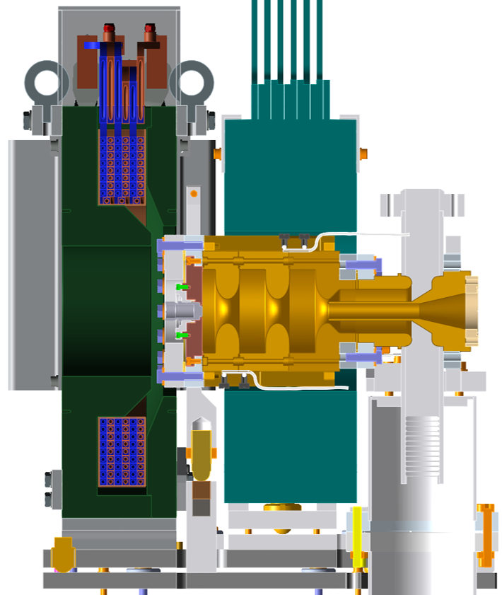
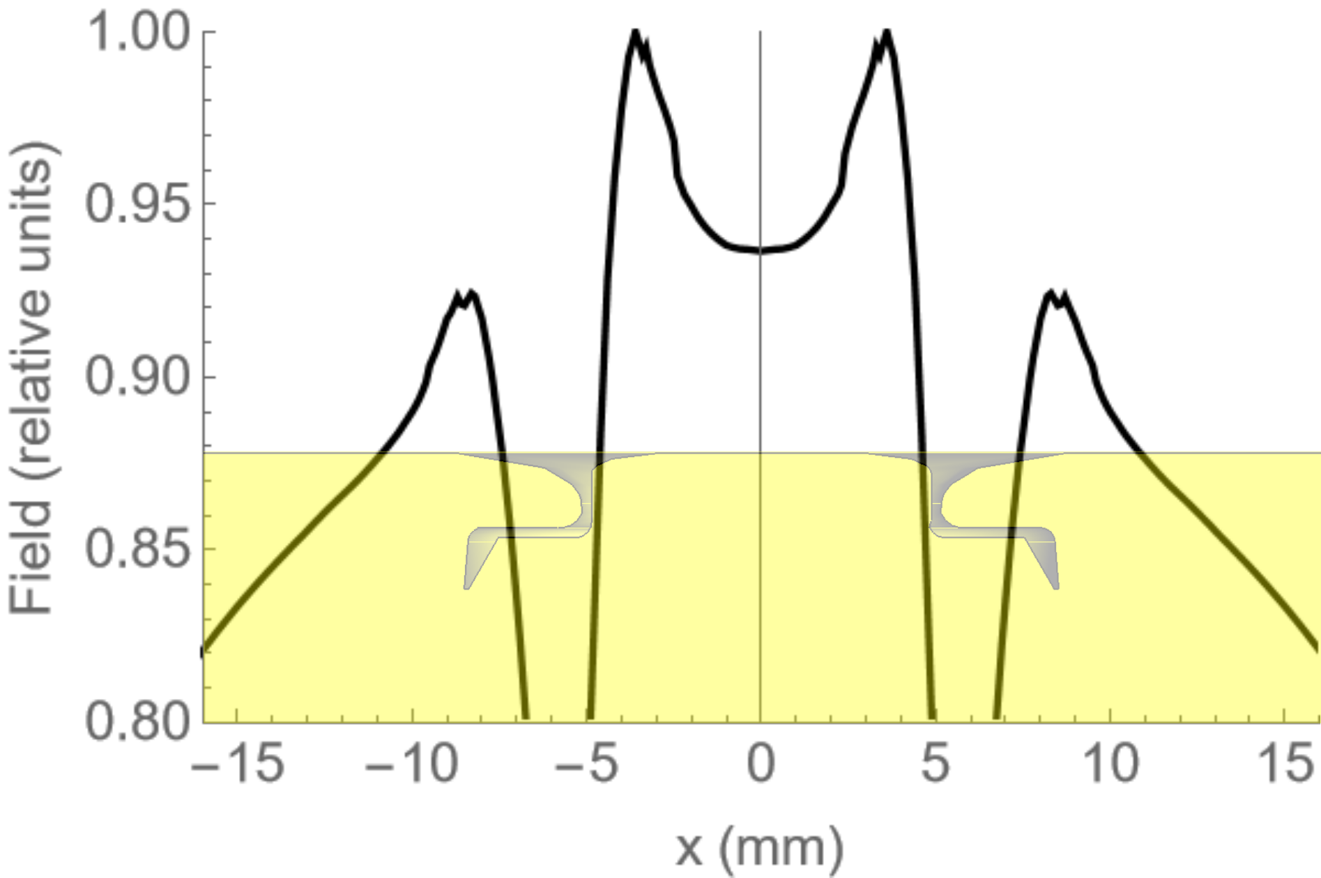
Figs. 1 and 2 show the upgraded CLARA gun and mechanical design of the gun region. The gun incorporates a main solenoid magnet to allow beam focussing, and ‘bucking’ solenoid to cancel the solenoid field on the surface of the cathode. The design of the cathode exchange mechanism was influenced by a project to develop an alternative high repetition rate gun for CLARA (up to 400 Hz). This development sought to optimise performance of the gun, through control of electromagnetic field by shaping of inner gun surfaces including those of the cathode areas. A key element of this design was the elliptical design of cavity irises and the profile of the cathode insert (plug). The cathode plug profile has a flat central section of 6 mm diameter and an elliptical edge (rim). The gun electric field is enhanced at the cathode edges by the plug opening. In the design the ellipticity was optimised to maximise the ratio of the peak field in the centre of the cathode to that on the edges. An elliptical shape falling back to 0.6 mm from the cathode face was found to be the optimum plug shape, achieving a ratio of around 0.9. In other words, even when optimised, the peak field on the cathode edges was still slightly larger then the field in the centre (as can be seen in Fig 3).
The CLARA machine and injector beamline is described elsewhere [11]; the injector line consists of the gun and a beampipe approximately 1m long containing a lightbox through which the photoinjector laser is directed onto the cathode, a wall current monitor to measure beam charge, and a scintillation (YAG) screen on which the beam and the dark current emerging from the gun is observed. Immediately after the screen is the first main accelerating cavity where electrons gain their full energy. The beampipe is nominally 35 mm radius, but the coupler and light box assembly contain narrower apertures through which the beam and dark current pass before they reach the first screen.
III CLARA DARK CURRENT SIMULATION OUTLINE
Finite element method (FEM) simulations of the dark current generation and transport in the CLARA injector have been developed using CST. Both the electric field in the gun and the dark current are simulated within CST, based on FEM methods. The solenoid magnetic field is simulated in an external code OPERA [13] and imported into CST. This method provides a full 3-D model of the situation. It was first used for simulations of dark current in the CLARA gun with its original bulk photocathode and was able to provide a level of agreement with experimental observations [14]. When the CLARA gun was upgraded the CST simulations were modified to reflect the changes, and the complete model used here includes the gun with new cathode geometry, the coupler geometry, and the beam pipe extending through the light box and its narrower aperture, up to the first beam diagnostic screen.
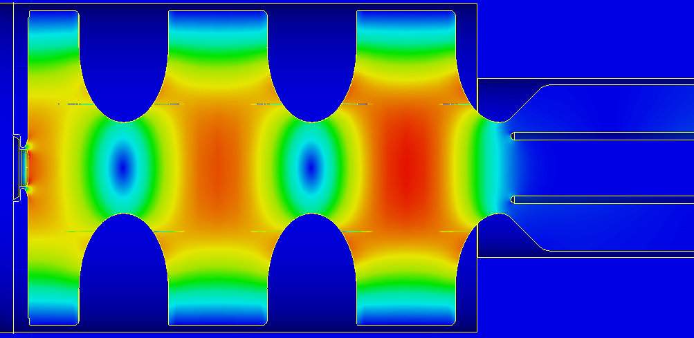
The gun EM field is simulated using the FEM field solver of CST, using the gun and coupler section of the model. Fig. 3 shows the solved electric field of the gun in the x-z plane. To simulate dark current production and transport the PIC simulation of CST is used, which incorporates the EM field generated from the previous step, and the combined gun solenoid and bucking solenoid field modelled by the OPERA package. The dark current generated from the gun surfaces uses the Fowler Nordheim (FN) model of field emission, describing the current density of surface field emission, depending exponentially on the applied electric field
| (1) |
where and depend on the properties of surface and material (work function and surface roughness). In the simulation field emission points are uniformly distributed over the gun surfaces and the FN model determines the emitted current density at each point using the simulated electric field there.
The emitted particles are then tracked through the gun and solenoid fields to the position of the first screen. There are several features related to the discretisation of the FEM nature of this model. A tetrahedral mesh is used solve the EM field, which better describes curved surfaces compared to a hexahededral mesh; however the PIC simulation uses a hexahedral mesh to track the particles through the field. The particle generation uses triangulation to model emission points over the 3-D surfaces of the gun. The parameters of each discretisation, and compatibility between them, may affect both the fine and coarse results of the simulation. In the simulations of the simpler pre-upgrade gun [14], convergence of the amount of charge emitted for each surface was achieved by choosing a sufficiently dense set of mesh parameters. The more complex geometries of the upgraded gun proved did not allow convergence to be achieved. The goal of the studies was to examine the appearance of the dark current on the screen, and so convergence of the total emitted and transported charge was not necessary, as long as the parameterisation was sufficent to achieve physically reasonable results (i.e. demonstrating sufficient symmetry and uniformity). Thus the meshing parameters and the field emission parameters (FN parameters and ) where adjusted to achieve this.
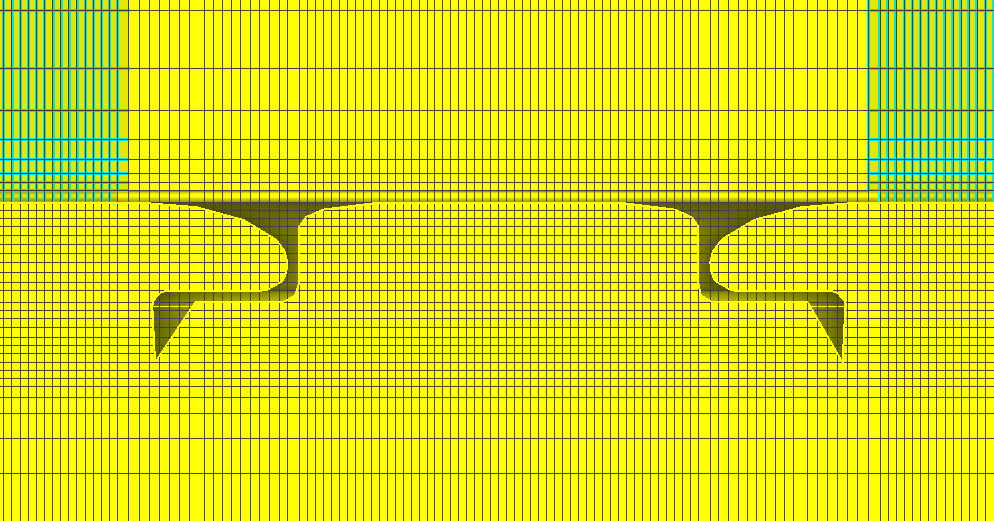
The PIC mesh had different density in different regions of the gun, depending on the geometric complexity of each region. Fig 4 shows a closer detail of the meshing density in the area of the cathode where the most complex geometry in the model arises. The smallest mesh size in the transverse and longitudinal dimensions is 0.2 mm.
IV RESULTS AND DISCUSSION
Following development of the CST model of the upgraded CLARA gun, several experimental observations of dark current were made during the commissioning of the gun, and an attempt was made to match these in the CST simulation. Several different photocathodes of different materials and preparations were used in the commissioning which are detailed in [12].
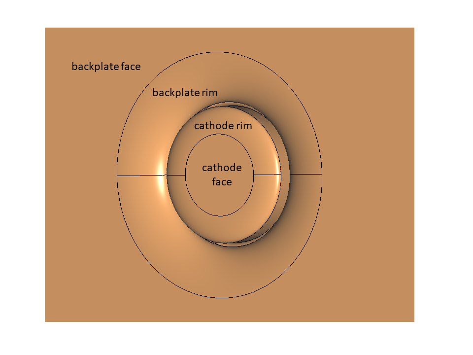
Previous general characteristics of the dark current, such as 6D phase space distributions, have previously been reported [14], and similar general characteristics were seen here. This included the finding that, for nominal operating parameters and assuming uniform emission properties over all surfaces, only the backplate and cathode regions contributed to dark current escaping the gun. In the upgraded gun simulations is was found that the emission from cathode region (including backplate rim) dominated the beamline dark current so greatly that the backplate emission was omitted from the final simulations. Other characteristics included a large energy spread of the dark current from each surface, with significant dark current at the nominal energy of the beam. There was not enough difference in the energy distributions from each surface to suggest the contributions from the flat cathode region and the rims could be separated and identified by dipole spectroscopy.
The main experimental observations presented the appearance of dark current on a scintillating screen near the gun, for different solenoid strengths. During operation of the first photocathode used in the commissioning of the CLARA gun (called cathode ‘#13’ see [12] ), the screen image was taken at 3 different solenoid/bucking-solenoid configurations, showing distinctively different coarse and fine features of the dark current. The solenoid field configurations included 1) the main solenoid on but the bucking solenoid off 2) the bucking solenoid set to a strength which cancels the main solenoid field on the cathode surface which is the nominal setting used for beam focussing 3) the bucking solenoid and main solenoid on but at strength where the field does not cancel on the cathode surface.
The measured and simulated screen images are shown in Fig. 5. For the simulated images, the colour map (middle row) used is the charge per 2D bin, to compare with the intensity colour map of the screen images.
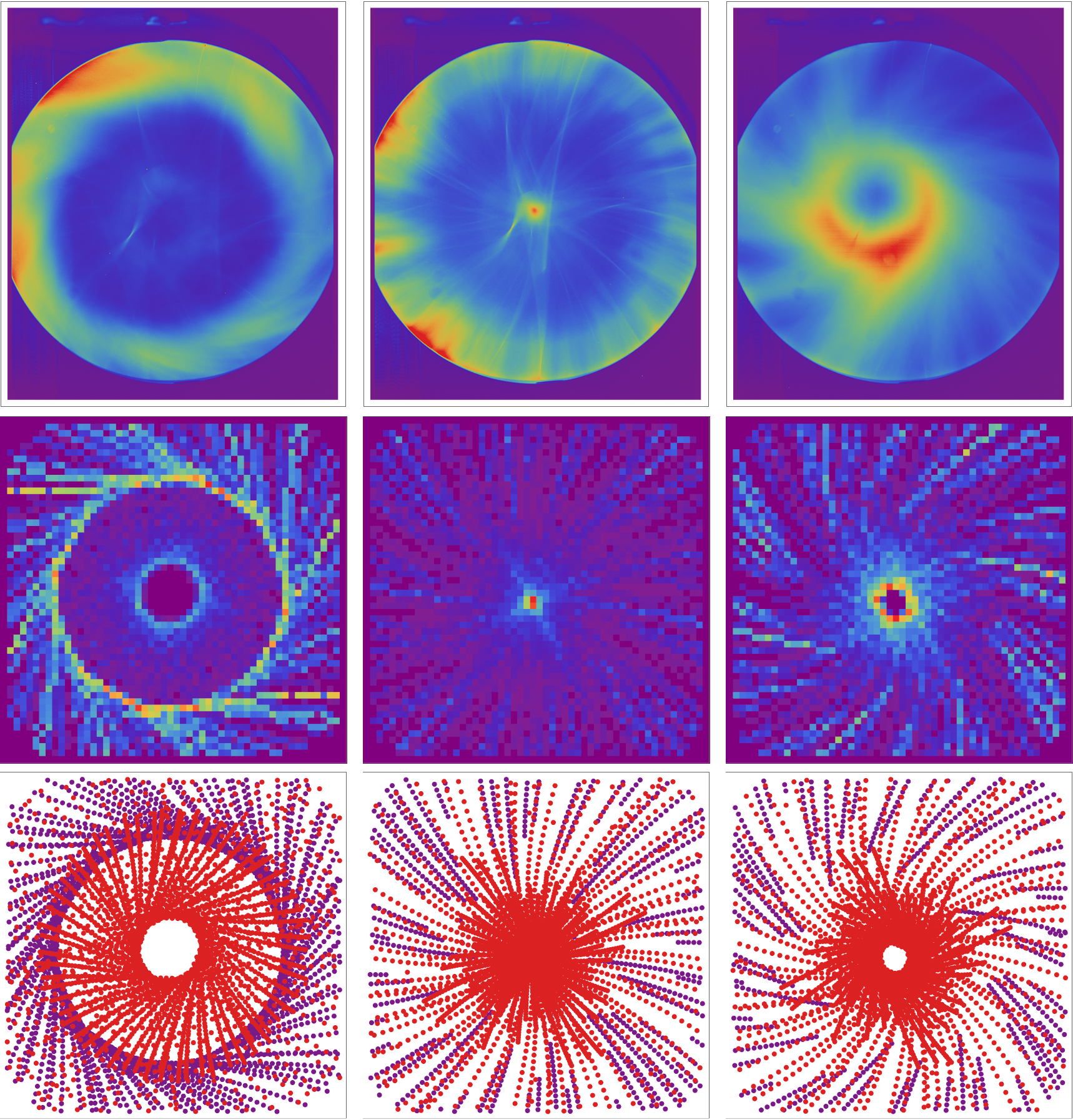
The notional gun field (at its nodal maxima) during these measurements was estimated to be 67 MV/m (using the measured RF power to the gun, a previously measured beam momentum vs RF power calibration, and a simplified simulation with a 1-D model of the field). This may omit some realistic features and errors in the actual gun field. Thus in the CST simulations the overall scaling of the gun field was set to a range (approximately 20 %) around 67 MV/m, and the results which gave the closest match to observed screen images are shown here. In a similar way the FN parameters for each surface, which influence the emitted dark current as described above, were adjusted in an ad-hoc manner to find a closer agreement with the data (a consistent set of FN parameters was chosen for all simulation results compared to data here).
It was found that contributions from the rims in the cathode region (see Fig. 2.) gave rise to the distinctive ‘ring’ features most closely matching the features of observations, which is clarified by the colour coded comparison of the separated contributions from only the rims (Fig 5 bottom row). The relative brightness of the ring features may indicate more intense emission from the rim surfaces compared to the flat central cathode surface which may be expected due to electric field enhancement. The surface roughness on the rims would be expected to be greater than the flat cathode surface (which is diamond polished) and microscopic field enhancement on the (greater) geometric surface imperfections of the rims would generate more field emission. A more complete formulation of the FN model [15] defines surface imperfections by a field enhancement factor and gives the field emission current (integrated over a RF cycle) as . While there is some uncertainty in using this model to extract quantitative values of for RF guns [15], the exponential form indicates strong dependence of the emission on surface quality, which supports the reasoning above. While the (non-enhanced) electric field strength varies over the cathode region, it reaches maxima on the rims (see Fig 3.) which again supports the increased contribution to dark current of the rims.
The results indicate that relatively bright central features (middle column of Fig. 5) are not necessarily due to field emission from the centre of the cathode. They may instead be field emission from the rims which are then focused to the centre of the screen by the solenoid. Some fine features seen in the screen images may be a result of non-uniformly distributed imperfections on the surfaces, which are not reproduced by the uniformly distributed emission points of the simulations.
There were other further observations made throughout the subsequent gun commissioning and operation of different photocathodes which support these findings. For example during the commissioning of a Mo/Cu hybrid photocathode (named ‘#7’) it was retracted for heat cleaning and reinserted; later another hybrid cathode (named ‘#16’) with different surface preparation (diamond-turned) was inserted. The appearance of dark current on the screen during these changes was observed and compared. This is shown in Fig 6 where approximately the same gun electric field and solenoid strength was used in all the images (note these approximately matched, but were slightly different to, those used in the middle column of Fig 6, with the solenoid field cancelled on the cathode surface). The images taken before and after retraction and reinsertion of the cathode highlight the dark current features from emitters on the cathode compared to those on the surrounding backplate and rim. Similarly the inserting of a different cathode shows a clear difference in some features and similarity on others, again allowing the identification of different sources and confirming the ability of the simulations to predict these features.
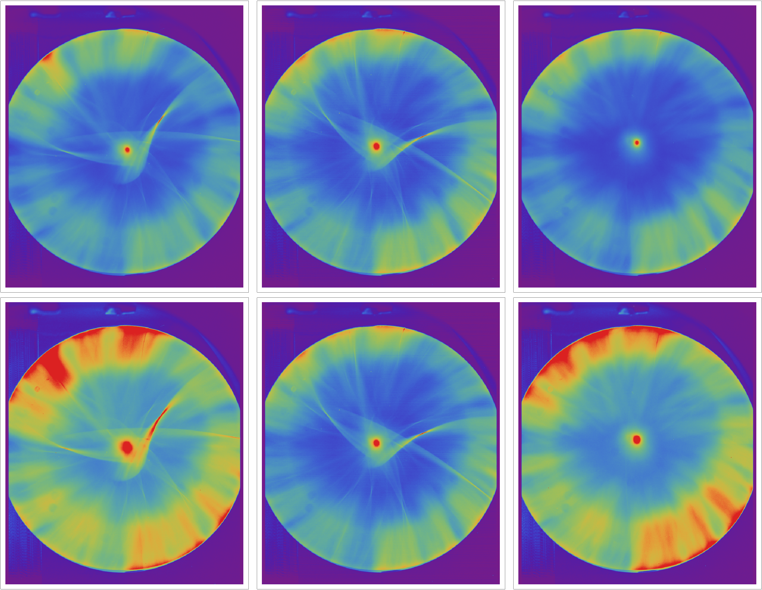
An interesting observation is the difference in brightness of the dark current on the screen for different cathodes and/or different insertions of the same cathode. This may be due to the effect of very small (m) differences in positioning of the cathode and/or the length of the different cathodes. The geometrical change this makes to the gun cavity may change the EM field strength on the cathode surfaces (as seen in [9]), and thus change the intensity of the dark current emission. A wall current monitor (WCM) located approximately 20 cm upstream of the screen was used to measure the dark current, which confirms the reduction in dark current (around 15 %) seen after retraction and reinsertion of the cathode seen in Fig 6.
V CONCLUSIONS
Despite the lack of quantitative convergence, the results above demonstrate the usefulness of simulations in the ability to characterize the effect of each emitting source on the screen pattern. In the screen images of the dark current the emission from the backplate and from the cathode insertion has been identified. This is clear due to the comparison of different experimental conditions (retraction and reinsertion of cathodes), and is also supported by the simulations, where different emission sources can be isolated, and shows some level of agreement with observation. For the CLARA gun, these observations lead to the following conclusions.
Field emission from the curved section of the backplate is significant and, for certain parameters, may dominate the dark current transported through the first part of the beam-line. For the nominal beam setting of the solenoids it appears as an outer bright ring on the screen.
Field emission from the cathode (flat surface and and the curved rim) leads to features observed in the central part of the screen, when the solenoid strength is set approximately to its nominal beam focussing setting. The central bright spot may not be due to ‘field emitters’ in the centre of the cathode, since simulations indicate field emission from the edge of the cathode may be focused to the centre of the screen.
There are several issues and uncertainties with the simulations that would require further work to evaluate further. There are various ways in which the electric and magnetic field in the simulations may differ from reality. At the emission surfaces where the particle energy is low, this may significantly affect the dynamics of the field emission. In simulation, meshing artefacts may affect the gun electromagnetic field shape, even for perfectly described geometries. Other effects which might be thought small may also be important; for example mutual coil excitation included in the modelling of combined solenoid and bucking solenoid field were observed to make a significant different to the simulated screen patterns. We do not have detailed in-situ 3-D measurements of the magnetic and electric fields, which may include other such small effects, to compare against the modelled fields.
VI ACKNOWLEDGEMENTS
We wish to thank members of ASTeC (Accelerator Science and Technology Centre) and Technology Departments of STFC (Science and Technology Facilities Council) for providing technical and operational support of the CLARA accelerator, which made these experiments possible. We wish to particularly thank I. Gessey and P. Tipping for development of the CST field emission simulations of the CLARA gun.
VII REFERENCES
References
- Frolich [2009] L. Frolich, Machine protection for FLASH and the European XFEL, Ph.D. thesis, University of Hamburg, Germany (2009).
- Clarke et al. [2014] J. A. Clarke et al., Clara conceptual design report, Journal of Instrumentation 9 (05), T05001.
- [3] L. K. Rudge et al., Single-shot Multi-MeV Ultrafast Electron Diffraction on VELA at Daresbury Laboratory, in Proceedings of the 6th International Particle Accelerator Conference. IPAC’15 (JACoW, Geneva, Switzerland) pp. 2278–2281.
- Lagzda [2019] A. Lagzda, VHEE Radiotherapy Studies at CLARA and CLEAR facilities, Ph.D. thesis, University of Manchester, UK (2019).
- Dowell et al. [2007] D. Dowell, E. Jongewaard, C. Limborg-Deprey, J. Schmerge, and A. Vlieks, Measurement and analysis of field emission electrons in the LCLS gun, in 2007 IEEE Particle Accelerator Conference (PAC) (2007) pp. 1299–1301.
- Huang et al. [2015] R. Huang, D. Filippetto, C. F. Papadopoulos, H. Qian, F. Sannibale, and M. Zolotorev, Dark current studies on a normal-conducting high-brightness very-high-frequency electron gun operating in continuous wave mode, Phys. Rev. ST Accel. Beams 18, 013401 (2015).
- Shao et al. [2016] J. Shao, J. Shi, S. P. Antipov, S. V. Baryshev, H. Chen, M. Conde, W. Gai, G. Ha, C. Jing, F. Wang, and E. Wisniewski, In situ observation of dark current emission in a high gradient rf photocathode gun, Phys. Rev. Lett. 117, 084801 (2016).
- [8] K. Szymczyk, J. A. Lorkiewicz, R. Nietuby, and J. K. Sekutowicz, Preliminary Results of the Dark Current Modelling for the Polfel Superconducting Lead Photocathode, in Proceedings of the 38th International Free Electron Laser Conference FEL’17 (JACoW, Geneva, Switzerland) pp. 463–465.
- Shu et al. [2021] G. Shu et al., Dark current studies of an l-band normal conducting rf gun, Nuclear Instruments and Methods in Physics Research Section A: Accelerators, Spectrometers, Detectors and Associated Equipment 1010, 165546 (2021).
- [10] Computer simulation technology. https://www.cst.com.
- Angal-Kalinin et al. [2020] D. Angal-Kalinin et al., Design, specifications, and first beam measurements of the compact linear accelerator for research and applications front end, Phys. Rev. Accel. Beams 23, 044801 (2020).
- Noakes et al. [2023] T. C. Q. Noakes et al., Copper photocathodes for the modified 10 hz gun on the CLARA accelerator, in Proceedings of the 14th International Particle Acclerator Conference. IPAC’23, 14 (JACoW, Geneva, Switzerland, 2023) pp. 1408–1411.
- [13] Opera electromagnetic and electromechanical simulation. https://www.3ds.com/products/simulia/opera.
- [14] F. Jackson, I. R. Gessey, J. W. McKenzie, B. L. Militsyn, and P. J. Tipping, Dark Current Studies in the CLARA Front-End Injector, in Proceedings of the 8th International Particle Accelerator Conference IPAC’17 (JACoW, Geneva, Switzerland) pp. 2779–2782.
- Chen et al. [2012] H. Chen, Y. Du, W. Gai, A. Grudiev, J. Hua, W. Huang, J. G. Power, E. E. Wisniewski, W. Wuensch, C. Tang, L. Yan, and Y. You, Surface-emission studies in a high-field rf gun based on measurements of field emission and schottky-enabled photoemission, Phys. Rev. Lett. 109, 204802 (2012).