MethodReferences
Versatile Optical Frequency Division with Kerr-induced Synchronization at Tunable Microcomb Synthetic Dispersive Waves
Abstract
Kerr-induced synchronization (KIS) provides a new key tool for the control and stabilization of the repetition rate of a cavity soliton frequency comb. It enables direct external control of a given comb tooth of a dissipative Kerr soliton (DKS) thanks to its capture by an injected reference laser. Efficient KIS requires its coupling energy to be sufficiently large, and hence both the comb tooth and intracavity reference power must be optimized, which can be achieved through higher-order dispersion that enables phase-matched dispersive waves (DWs), where comb teeth are on resonance. However, such a design is highly restrictive, preventing arbitrary use of reference wavelengths away from the DW(s). In particular, for large spectral separations from the main pump the cavity dispersion yields large detuning between comb teeth and their respective cavity resonances, thereby decreasing the coupling energy and rendering KIS to be highly inefficient or practically impossible. Here, we demonstrate an alternative KIS method where efficient synchronization can be tailored at arbitrary modes as needed. Using a multi-color DKS created from multi-pumping a microresonator, a synthetic DW at the second-color wavepacket can be selectively created where otherwise dispersion is far too large for KIS to be experimentally feasible. Since a unique group velocity for both colors exists thanks to cross-phase modulation, the repetition rate disciplining of the secondary color wavepacket through its KIS automatically translates into the DKS microcomb control. We first investigate this color-KIS phenomenon theoretically, and then experimentally demonstrate its control and tuning of the soliton microcomb repetition rate. As a consequence, we demonstrate optical frequency division that is uncoupled from the main pump that generates the DKS.
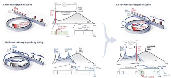
Optical frequency combs (OFCs) are, in their low noise state, an essential component in the metrology toolbox for frequency and time measurement [1, 2]. They can be used as a phase-coherent frequency multiplier/divider between the microwave and optical domains for optical frequency synthesis [3], optical clockworks [4, 5], time transfer [6, 7], and ultra-low noise microwave generation [8, 9], while also increasingly finding application in more widespread consumer technologies such as distance ranging [10]. Integrating such OFCs on chip has been a recurrent quest over the last decade, in particular with the demonstration of dissipative Kerr soliton (DKS) microcombs which convert a continuous wave (CW) pump into a periodically-extracted pulse train [11]. DKSs at their core rely on the dispersion compensation by Kerr nonlinearity present in several CMOS-compatible materials, such as silicon nitride (\ceSi3N4), allowing for low-cost and mass-scale fabrication of high quality factor microring [12] or Fabry-Perot resonators [13] through which DKSs can be generated with low pump power [14]. Although the combs’ technical requirements may vary from one application to another, the control and/or stabilization of their repetition rate is in general a key element [2]. In particular, optical frequency division (OFD) relies on pinning two comb teeth to stable lasers, leveraging the fundamental property that their noise will be divided onto the repetition rate by their comb tooth separation [15]. Although on-chip operation for the laser stabilization [16] and the comb generation [17, 18] can be achieved, the overall architecture mostly relies on lab-scale equipment for the comb-laser locking with only one degree of freedom (i.e. the main pump). Recently, Kerr-induced synchronization (KIS) has been demonstrated as an all-optical approach to address the technical challenge of optically locking the comb [19]. In KIS, the injection of another reference pump laser into the comb-generating resonator results in the closest comb tooth snapping onto the reference [Fig. 1(a)], enabling external control of two comb teeth through both pumps. This method has been successfully shown to enable all-optical OFD through locking of both pumps [19, 20], with performance on par with other techniques [17, 21].
Although KIS greatly simplifies an optical clockwork [19, 22], it can be challenging to implement for other OFD applications. First, it fixes the main pump, rendering the system stiff if low phase-noise is to be achieved. This is contrary to a typical external dual-pinning architecture, which uncouples the DKS generation from the locked reference lasers. Thus, OFD with KIS prevents the main pump from being directly freely tuned across the resonance to generate the DKS, or using the promising approach of self-injection locking for turnkey-DKS generation [23, 24, 25], which complicates further integration. Secondly, this KIS phase locking efficiency relies on the KIS coupling energy, which can be expressed as the geometrical mean of the intra-cavity power of the comb tooth and the reference pump upon synchronization [19, 20]. The injection of the reference laser at a dispersive wave (DW) enhances the KIS energy since the comb tooth is resonant, maximizing both the tooth and reference intracavity power. However, DWs are not always present, especially in microcombs with directly detectable, low repetition rates that are often achieved in resonators with pure quadratic dispersion. Without a DW, KIS can occur, but at a significantly higher reference pump power [20]. In addition, though the larger OFD factor provided by placing the reference far from the main pump would be preferred, the smaller KIS coupling energy due to the resonator dispersion is a hindrance, as the KIS bandwidth could be narrower than the laser linewidth, making synchronization practically unachievable. Here we propose a new scheme that uncouples the main pump soliton – which can remain free-running – with the all-optical OFD enabled through KIS, by using a multi-color cavity soliton system [26].
Physical concept of the color-KIS - Let’s remind of the multi-pumped DKS operation outside of synchronzisation. In this case, the second injected laser does not become a DKS comb tooth [Fig. 1(b)], yet cross-phase modulation (XPM) is sufficient to lock the group velocity of the auxiliary and DKS components in the cavity [27]. Thus, these two traveling waves only differ by their phase velocity mismatch, translating into the output waveguide as two frequency comb components with the same comb teeth spacing yet with a shift of carrier-envelope offset (CEO) from one another. Here, we refer to each component (i.e. the auxiliary and the DKS wave) as colors, defined by their respective phase velocity (CEO in the spectral domain). Interestingly, using this scheme enables a new phase matching condition at the second color [28], whose location is highly flexible since it can be widely tuned by hopping between cavity modes, or finely tuned through tuning within a cavity mode, without disrupting the DKS state. This results in the creation of DW(s) that can be harnessed, for instance, for spectral extension [26, 29], where high power comb teeth can be generated at frequencies of interest. As these new dispersive waves are not solely governed by cavity dispersion, but are instead tunable based on the secondary laser frequency (i.e. tuning the CEO difference between the colors), we refer to them as synthetic dispersive waves. Here, we harness both KIS and the synthetic dispersive waves produced in multi-color solitons [Fig. 1(c)]. By injecting an auxiliary laser on resonance with a cavity mode, hence shifted from its nearest comb tooth because of the resonator dispersion, we create a second color at the same group velocity as the DKS, yet with a spectral shift of tens of gigahertz from the DKS carrier-envelope offset frequency. We show that the second color, which automatically presents at least one DW, can undergo a power efficient KIS by a reference pump (a third laser injected into the resonator). Through XPM, the KIS of the second color is automatically transferred onto the DKS, enabling control and/or stabilization of the DKS repetition rate. Importantly, in this scheme the main pump does not require any locking, since all its noise will be absorbed by the spectral offset between the two comb components while the repetition rate remains locked through the OFD between the auxiliary and reference lasers. Also, as this color-KIS does not impose specific requirements on the resonator dispersion, it widely expands the range of devices and scenarios in which KIS can be utilized to synchronize DKS microcombs to optical references.
Theoretical study of the color-KIS – We aim to study this effect theoretically. The addition of another driving field could be introduced in two fashions which modify the Lugiato-Lefever equation (LLE) that is commonly used to study damped and driven Kerr nonlinear resonators within a mean-field limit. First, it can be simply introduced in the single LLE by adding another pump term that accounts for the frequency offset due to the cavity dispersion from the fixed frequency grid spaced by (defined by the DKS repetition rate), as shown in [30]. Although this multi-pump LLE approach captures the Kerr-induced synchronization phenomenon [19], it does not fully capture the multi-color aspect. Instead, a set of coupled equations can be used, the first one at the DKS phase while the second presents a phase offset, with the two coupled through XPM. To account for the full nature of the system and the nonlinear mixing in the phase domain, another set of equations shifted by an integer multiple of this phase offset, hence accounting for parametric nonlinear phase mixing [31], can be introduced. However, the creation of a so-called two-dimensional comb [32] is not necessary to understand the concept of color-KIS that we focus on in this work, and hence it is sufficient to focus on the DKS color driven by the main pump with power , and the secondary color pumped by the auxiliary laser with power such that:
| (1) | ||||
| (2) | ||||
with and the respective Fourier transforms of and in the azimuthal angle /mode of the microring. The resonator properties that we are using are from the experimental system such that W-1m-1 is the effective nonlinearity calculated at the main pump [19, 26], GHz the total loss rate, the external coupling rate (i.e., the coupling and intrinsic quality factor respectively), µm the resonator circumference, and is the integrated dispersion accounting for the DKS repetition rate THz. The external parameters we experimentally control are the main and auxiliary pump power mW and mW, respectively, is the auxiliary pumped mode, and and are the detuning of the main and secondary color respectively, with the detuning of the auxiliary pump relative to its resonance mode and the resonance frequency at mode .
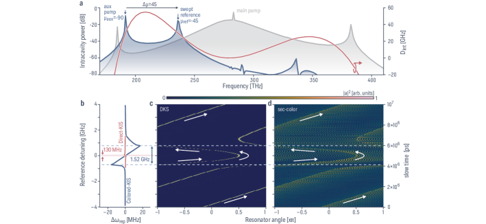
Since the two colors are coupled through XPM, they exhibit the same group velocity, resulting in two equally-spaced comb components offset from one another by . As presented in refs [32, 31], this multi-color LLE formalism allows for straightforward comprehension of the phase matching resulting in the creation of DWs. Since the secondary color is offset from the main DKS by , any zero crossing of will exhibit synthetic DW features at this color. With an anomalous dispersion regime being defined by a concave quadratic integrated dispersion, at least one DW will be created at the secondary color (e.g., at ). For the geometry we study in the experiments presented later, higher-order dispersion is present, resulting in a roll-off in with an eventual zero-crossing and generation of a DKS-DW. We auxiliary pump away from the DKS-DW, with the higher-order dispersion providing a phase-matching point that is on the same side of the main pump [Fig. 2(a)].
We simulate the multi-color LLE system with a main pump at , an auxiliary pump at , and dispersion profile presented in Fig. 2(a). We introduce the reference laser that triggers the synchronization through the inclusion in Eq. 2 of an additional driving force , with , the reference pump detuning, and being the mode (relative to the main pump) at which we send the reference pump. We adiabatically and linearly sweep the detuning of the reference pump while seeding the initial solution with the soliton and secondary color solution for and , respectively, and keeping both main and auxiliary pump fixed.
When out-of-synchronization, the simulation highlights that the auxiliary and DKS colors travel at the same group velocity [Fig. 2(c-d)] since the DKS drifts in at the same rate as the secondary color. Once the reference laser is within the KIS bandwidth, it captures the secondary-color comb tooth, stretching or compressing the microcomb and changing the secondary-color repetition rate [Fig. 2(b)] with a slope given by the optical frequency division (OFD) factor set by , and hence controlling its group velocity. Because of the XPM binding, the DKS must follow any variation of group velocity imprinted onto the secondary color, which is apparent using the two-wave LLE formalism as they drift together. Hence, even if the the synchronization is performed on the secondary-color, the DKS repetition rate can be controlled. We can compare this scheme against a direct KIS at the same mode , where the DKS comb does not present any DW and its shape closely follows a spectral envelope. The KIS bandwidth , with , being the total energy with the soliton or secondary color, and is directly proportional to the energy of the synchronization mode. Hence, for a fair comparison, we have chosen this particular configuration as it conveniently results in the same OFD factor for the direct and color-KIS, with only a change of sign changing the direction of the trend against reference pump detuning. In the direct-KIS scenario, the available comb tooth energy is considerably lower, by about 17 dB compared to the synthetic DW. In addition, the intracavity reference pump does not experience resonance enhancement (and could be considered single-pass) due to the close to 40 GHz offset of the comb and its nearest cavity mode – with assumed losses resulting in an offset of more than 40 resonance linewidths – preventing any significant resonant power build-up. This translates to a KIS bandwidth about 10 times smaller than the color-KIS bandwidth, with 130 MHz and 1.53 GHz synchronization bandwidths, respectively [Fig. 2(b)].
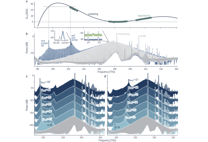
Experimental nonlinear characterization of the microring – Experimentally, we use silicon nitride (\ceSi3N4) microring with a nominal thickness of nm embedded in \ceSiO2 with a designed ring width of nm, presenting a similar dispersion profile as the one used in simulations in Fig. 2. The higher-order dispersion results in roll-off, enabling the creation of new synthetic dispersive wave phase-matching in the 230 THz range (i.e., 1300 nm range) for auxiliary pumping in the 190 THz range (i.e., 1550 nm range), and vice-versa. The experimental dispersion is measured using wavemeter-calibrated resonance frequencies of the first order transverse electric mode [Fig. 3a]. The experimental setup is discussed in detail in Appendix S.1. To generate the DKS, we use a 283 THz pump with about 150 mW on-chip power. The DKS is adiabatically accessed using a 308 THz counterpropagating cooler laser that pumps a fundamental transverse magnetic mode [Fig. 3b], which thermally stabilizes the resonator and enables long-term operation of the DKS state [34, 33]. To generate the secondary color, we use continuously tunable lasers (CTLs) spanning between 184 THz to 198 THz with about 2 mW of on-chip power, and 227 THz to 232 THz with about 1 mW of on-chip power. One of these lasers acts as the auxiliary pump that creates the second color (i.e., is fixed), while the other is used as the reference. It is apparent that no direct-KIS could occur between the DKS and the secondary color since the two comb components are separated by about 40 GHz (resolved with an optical spectrum analyzer; see left inset to Fig. 3b). We further verify the flexibility and efficiency of the creation of new synthetic DWs by auxiliary pumping different modes in the 190 THz band and 230 THz band. Figure 3c-d highlights the creation of a new DW in these other laser bands, and how the synthetic DW spectral position, which will determine where the KIS reference laser is applied, can be flexibly controlled by tuning the auxiliary laser frequency. A significant improvement of 25 dB (190 THz band auxiliary pump) or 32 dB (230 THz band auxiliary pump) of the comb tooth power available at the new DW where the color-KIS will happen is observed compared to the nearest DKS comb tooth. Along with the possibility to send the reference on-resonance, it confirms the theoretical investigation previously conducted that color-KIS will be more highly efficient than conducting a direct-KIS at these modes.
DKS repetition rate entrainment from color-KIS – To characterize the color-KIS we measure at the same time the repetition rate and the frequency offset between the reference laser and the secondary color (see experimental setup in Appendix S.1). As our focus is on DKS repetition rate control, the repetition rate of the system is measured only at the DKS color. This is done by measurement around 272 THz, where the secondary color presents negligible power in comparison to the DKS, as evident through a comparison of the spectra with and without the auxiliary/reference pumps [Fig. 3b]. We use an electro-optic comb apparatus [19, 35] to modulate two adjacent DKS comb teeth and frequency translate THz to a detectable microwave beat note; an example spectrum is shown in the right inset to Fig. 3b. We sweep the reference laser using an electrical ramp signal sent to the CTL piezo element, enabling small detuning to be studied, and measure both and by recording simultaneously their temporal trace with a fast oscilloscope. We then process these data to create a spectrogram where the temporal dependence of and are obtained. The detuning calibration is obtained through beating the reference laser against the secondary color comb tooth while bypassing the resonator (i.e., no nonlinearity, hence no synchronization), calibrating the amplitude and the zero of the detuning. For more details, the complete procedure is described in Appendix S.2.
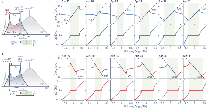
First, we use the 190 THz CTL as the auxiliary pump generating the secondary color, and keep its detuning fixed. We use the 230 THz CTL to act as the reference and it is frequency swept close to the secondary color comb tooth [Fig. 4a]. We use the different modes that have been presented in Fig. 3c-d, resulting in a variation of to . A clear change in the repetition rate following a linear trend with the reference detuning occurs when is locked to zero, consistent with conventional KIS behavior, except in these measurements is at the second color while the measurement of the repetition rate variation is at the DKS color, highlighting the XPM interplay linking the color-KIS to the DKS. We verify the linear trend of the repetition rate entrainment by overlaying the reference laser detuning divided by , which closely matches . We note here that this linear trend is plotted without offset or scaling, since the zero detuning is accurately calibrated using the technique presented in Appendix S.2 and since the OFD factor is a simple comb tooth counting. We can then switch the system, where the 230 THz CTL becomes the fixed auxiliary pump creating the secondary color while the 190 THz CTL becomes the swept reference pump [Fig. 4b]. Similar results as previously described are obtained, yet this time the OFD coefficient is negative. The repetition rate entrainement slope becomes negative when , and is once again accurately captured by a simple linear trend accounting for . We note that this experiment has been conducted while maintaining the same exact DKS state, highlighting the little impact the secondary color and its synchronization has on the stability of the DKS, further providing flexibility to the system for on-the-fly reconfigurable OFD.
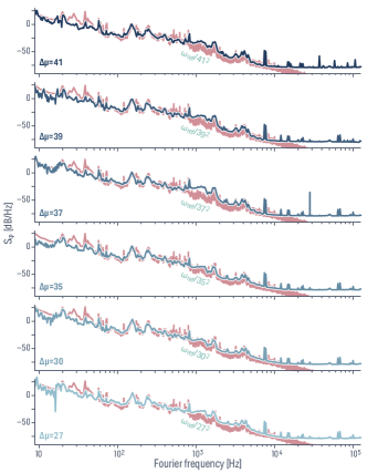
DKS repetition rate phase noise from color-KIS – We investigate the phase noise of the DKS repetition rate while the second color becomes synchronized. For the different OFD factors presented in Fig. 4, we enter the color-KIS regime and lock both auxiliary and reference lasers to independent fiber Mach-Zehnder interferometers (MZIs) with a 10 MHz free spectral range, while the main pump and cooler pump are free running. Using a third similar MZI, we measure the optical phase noise of both pump lasers. We note that in this measurement we account for the noise of both lasers; however, since the 230 THz laser carries larger phase noise while locked than the 190 THz laser (see Appendix S.3), only accounting for the former to compare against phase noise enables verification of OFD. For each value of , the repetition rate is well-matched to the laser phase noise divided by the OFD factor [Fig. 5]. Although the repetition rate entrainement presented in Fig. 4 already demonstrated OFD based on the color-KIS technique, these additional phase noise measurements highlight that the XPM-mediated transfer of synchronization of the second color onto the DKS does not carry additional noise, so that color-KIS can be used to stabilize a DKS repetition rate indirectly. We further note that for , we have swept the reference pump over a range of about 120 MHz at a 75 Hz rate following a triangular waveform, and confirmed that no additional noise is present in the repetition rate phase noise. This is consistent with being locked for both colors, while the frequency offset between the two combs is not. Essentially, while in the color-KIS regime, all of the phase noise of the main pump is transferred onto the carrier-envelope offset noise of the DKS.
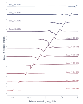
Large tunability of color-KIS frequency – Finally, we address the large tunability that the color-KIS enables. In contrast to the standard-KIS scheme, the color-KIS does not occur on the fixed frequency markers defined by the repetition rate and the main pump (i.e., the CEO frequency). Instead, the secondary colors live at a CEO offset from the main pump, which can be widely tuned through mode hopping between cavity resonances, as previously demonstrated [Fig. 3(c)-(d)]. Additionally, a finer tuning of the CEO frequency offset of the second color can be obtained through auxiliary pump detuning from its resonance, resulting in the tuning of the synthetic DW [28]. In particular, since the quality factor and coupling regime requirements are much less stringent than for DKS generation, one can harness the natural overcoupling at lower frequencies than the main pump from straight-waveguide coupling [36], resulting in large secondary color CEO offset tunability while still dropping significant auxiliary power from the waveguide to the cavity. The repetition rate of the DKS remaining mostly unperturbed with the auxiliary pump detuning enables one to tune the secondary-color comb tooth at which the color-KIS occurs. We demonstrate this effect experimentally using a OFD factor between the auxiliary and reference pump in the same DKS presented previously [Fig. 6]. The reference laser is swept, similarly to Fig. 4, while the auxiliary pump is fixed. The detuning of the auxiliary pump enables all the comb teeth of the secondary color to also be shifted by , thus shifting the color-KIS window accordingly. We demonstrate a tuning of over 10 GHz of the KIS window with 5 mW of on-chip power for both pumps, respectively, corresponding to a tunability of about ten times the optimized color-KIS bandwidth at this power when both pumps are at the center of their respective resonances. This tunability is only limited by the available power of the auxiliary pump, and could be further increased by using a more powerful laser while remaining in the thermal stability range of the DKS. Such tunability is a key feature of the color-KIS scheme, as it enables synchronization to occur at a precise target frequency, for instance to match a fixed frequency ultra-stable laser.
Discussion – In conclusion, we have demonstrated a novel way to efficiently access the Kerr-induced synchronization regime, enabling cavity soliton repetition rate control, and optical frequency division with all-optical synchronization of the comb. Using the fundamental group velocity binding between a DKS color and a secondary color created by an auxiliary laser traveling in the same microring resonator, we create new phase-matching conditions which enable new synthetic DWs that can be used for synchronization, and whose spectral locations can be flexibly tuned. Compared to synchronization to a reference laser at the same frequency using a single-pumped DKS, the comb tooth power is orders of magnitude larger while providing on-resonance operation for the reference laser to efficiently transfer its power inside the resonator. We show theoretically that the KIS bandwidth for a similar situation between direct and color-KIS is increased by at least an order of magnitude. Experimentally, we have demonstrated this effect using an integrated microring resonator, where repetition rate entrainment according to the optical frequency division factor between the auxiliary and the reference pump is verified. The spectral separation between the auxiliary and reference pump, and hence the division factor, can be widely controlled with respect to the underlying cavity dispersion without disrupting the stability of the DKS. We also show that the locking of the group velocity of the second-color through auxiliary and reference pump locking in the color-KIS regime is transferred onto the DKS repetition rate in a noiseless fashion, despite the indirect control of the DKS through the XPM-coupled secondary color. Finally, we have demonstrated the versatility of the color-KIS approach in comparison to the standard KIS one, where the synchronization frequency (and window) can be largely tuned without impacting the DKS. Our work enables a new efficient way to control the large repetition rate of integrated microresonator combs, in particular in situations where the cavity dispersion could otherwise prevent direct KIS.
We further discuss a few important implications of the color-KIS effect. For example, KIS-enabled optical frequency division has recently been shown in the context of low noise microwave generation with a greatly simplified architecture [21]. Our color-KIS scheme enables further important simplifications. Indeed, it is interesting to note that the main pump does not play a role in the repetition rate control and stabilization since the CEO offset between colors is unlocked and therefore uncoupled from optical frequency division approach. This enables the main pump to be freely tuned as needed to generate the DKS, without further conditions on its stability. In addition, although we have mostly focused on demonstrating the control of the single repetition rate of the different colors, it is important to point out that the secondary color forms its own frequency comb whose repetition rate can also be detected and stabilized. As a result, the color-KIS scheme brings the possibility to coherently phase lock an auxiliary laser to an ultra-narrow linewidth laser, through the repetition rate feedback onto the auxiliary laser. As noted above, in color KIS, such a scheme is independent of the main pump; indeed, the main DKS essentially acts as an intermediary whose XPM interactions with the second color enable a single group velocity to exist. Finally, the creation of synthetic DWs can be extended to other colors, which has been demonstrated to expand the comb bandwidth well beyond an octave [26], and hence the color-KIS scheme may find application in the stabilization of such ultra-broadband integrated frequency combs. Beyond the above, our work could find direct application in distance ranging while enabling new techniques for fundamental studies of DKS dynamics in micrometer-scale resonators.
References
- [1] Fortier, T. & Baumann, E. 20 years of developments in optical frequency comb technology and applications. Communications Physics 2, 1–16 (2019).
- [2] Diddams, S. A., Vahala, K. & Udem, T. Optical frequency combs: Coherently uniting the electromagnetic spectrum. Science 369, eaay3676 (2020).
- [3] Spencer, D. T. et al. An optical-frequency synthesizer using integrated photonics. Nature 557, 81–85 (2018).
- [4] Newman, Z. L. et al. Architecture for the photonic integration of an optical atomic clock. Optica 6, 680 (2019).
- [5] Oelker, E. et al. Demonstration of 4.8 × 10⁻¹⁷ stability at 1 s for two independent optical clocks. Nature Photonics 13, 714–719 (2019).
- [6] Giorgetta, F. R. et al. Optical two-way time and frequency transfer over free space. Nature Photonics 7, 434–438 (2013).
- [7] Caldwell, E. D. et al. Quantum-limited optical time transfer for future geosynchronous links. Nature 618, 721–726 (2023).
- [8] Tetsumoto, T. et al. Optically referenced 300 GHz millimetre-wave oscillator. Nature Photonics 15, 516–522 (2021).
- [9] Xie, X. et al. Photonic microwave signals with zeptosecond-level absolute timing noise. Nature Photonics 11, 44–47 (2017).
- [10] Riemensberger, J. et al. Massively parallel coherent laser ranging using a soliton microcomb. Nature 581, 164–170 (2020).
- [11] Kippenberg, T. J., Gaeta, A. L., Lipson, M. & Gorodetsky, M. L. Dissipative Kerr solitons in optical microresonators. Science 361, eaan8083 (2018).
- [12] Liu, J. et al. High-yield, wafer-scale fabrication of ultralow-loss, dispersion-engineered silicon nitride photonic circuits. Nature Communications 12, 2236 (2021).
- [13] Wildi, T., Gaafar, M. A., Voumard, T., Ludwig, M. & Herr, T. Dissipative Kerr solitons in integrated Fabry–Perot microresonators. Optica 10, 650–656 (2023).
- [14] Stern, B., Ji, X., Okawachi, Y., Gaeta, A. L. & Lipson, M. Battery-operated integrated frequency comb generator | Nature. Nature 562, 401–405 (2018).
- [15] Fortier, T. M. et al. Generation of ultrastable microwaves via optical frequency division. Nature Photonics 5, 425–429 (2011).
- [16] Liu, K. et al. 36 Hz integral linewidth laser based on a photonic integrated 4.0 m coil resonator. Optica 9, 770–775 (2022).
- [17] Kudelin, I. et al. Photonic chip-based low noise microwave oscillator (2023). eprint 2307.08937.
- [18] Sun, S. et al. Integrated optical frequency division for stable microwave and mmWave generation arXiv 2305.13575 (2023).
- [19] Moille, G. et al. Kerr-induced synchronization of a cavity soliton to an optical reference. Nature 624, 267–274 (2023).
- [20] Wildi, T., Ulanov, A., Englebert, N., Voumard, T. & Herr, T. Sideband injection locking in microresonator frequency combs. APL Photonics 8, 120801 (2023).
- [21] Sun, S. et al. Kerr optical frequency division with integrated photonics for stable microwave and mmWave generation arXiv 2402.11772 (2024).
- [22] Moille, G. et al. Octave Spanning Microcomb Dispersive Wave Optimization from Self-Balanced Soliton under Kerr-Induced Synchronization. In Frontiers in Optics, FTh3E–2 (2023).
- [23] Shen, B. et al. Integrated turnkey soliton microcombs. Nature 582, 365–369 (2020).
- [24] Ulanov, A. E. et al. Synthetic reflection self-injection-locked microcombs. Nature Photonics 1–6 (2024).
- [25] Voloshin, A. S. et al. Dynamics of soliton self-injection locking in optical microresonators. Nature Communications 12, 235 (2021).
- [26] Moille, G. et al. Ultra-broadband Kerr microcomb through soliton spectral translation. Nature Communications 12, 7275 (2021).
- [27] Wang, Y. et al. Universal mechanism for the binding of temporal cavity solitons. Optica 4, 855 (2017).
- [28] Qureshi, P. C. et al. Soliton linear-wave scattering in a Kerr microresonator. Communications Physics 5, 1–8 (2022).
- [29] Zhang, S., Silver, J. M., Bi, T. & Del’Haye, P. Spectral extension and synchronization of microcombs in a single microresonator. Nature Communications 11, 6384 (2020).
- [30] Taheri, H., Matsko, A. B. & Maleki, L. Optical lattice trap for Kerr solitons. The European Physical Journal D 71 (2017).
- [31] Shandilya, P. H., Moille, G., D’Aguanno, G., Srinivasan, K. & Menyuk, C. R. A study of dual-pumped microresonator solitons using 3-Wave equations. In Frontiers in Optics, JW4A–48 (2023).
- [32] Moille, G. et al. Two-Dimensional Nonlinear Mixing Between a Dissipative Kerr Soliton and Continuous Waves for a Higher-Dimension Frequency Comb. arXiv 2303.10026 (2023).
- [33] Zhou, H. et al. Soliton bursts and deterministic dissipative Kerr soliton generation in auxiliary-assisted microcavities. Light: Science & Applications 8, 50 (2019).
- [34] Zhang, S. et al. Sub-milliwatt-level microresonator solitons with extended access range using an auxiliary laser. Optica 6, 206 (2019).
- [35] Stone, J. R. & Papp, S. B. Harnessing Dispersion in Soliton Microcombs to Mitigate Thermal Noise. Physical Review Letters 125, 153901 (2020).
- [36] Moille, G. et al. Broadband resonator-waveguide coupling for efficient extraction of octave-spanning microcombs. Optics Letters 44, 4737 (2019).
- [37] Crameri, F. Scientific colour maps. Zenodo (2023).
- [38] Crameri, F., Shephard, G. E. & Heron, P. J. The misuse of colour in science communication. Nature Communications 11, 5444 (2020).
- [39] Moille, G., Li, Q., Xiyuan, L. & Srinivasan, K. pyLLE: A Fast and User Friendly Lugiato-Lefever Equation Solver. Journal of Research of the NIST 124, 124012 (2019).
- [40] Virtanen, P. et al. SciPy 1.0: Fundamental algorithms for scientific computing in Python. Nature Methods 17, 261–272 (2020).
Acknowledgments
The photonic chips were fabricated in the same fashion as the ones presented in [19].
The Scientific colour map batlow [37] and subsequent color set is used in this study to prevent visual distortion of the data and exclusion of readers with colour-vision deficiencies [38].
We acknowledge partial funding support from the Space Vehicles Directorate of the Air Force Research Laboratory, the Atomic–Photonic Integration programme of the Defense Advanced Research Projects Agency, and the NIST-on-a-chip program of the National Institute of Standards and Technology. P.S and C.M. acknowledges support from the Air Force Office of Scientific Research (Grant No. FA9550-20-1-0357) and the National Science Foundation (Grant No. ECCS-18-07272). We thank Sean Krzyzewski and Marcelo Davanço for insightful feedback.
Author Contributions
G.M. and K.S. led the project. G.M. designed the resonators and performed the measurements and simulations. P.S. and C.M. helped with the theoretical and numerical understanding. A.N. and G.C. helped with the experimental understanding. K.S. helped with data analysis. G.M. and K.S. wrote the manuscript, with input from all authors. All the authors contributed and discussed the content of this manuscript.
Competing Interests
G.M., C.M. and K.S have submitted a provisional patent application based on aspects of the work presented in this paper.
Data availability
The data that supports the plots within this paper and other findings of this study are available from the corresponding authors upon request.
Code availability
The simulation code is available from the authors through the pyLLE package available online [39], with a modification that is available upon reasonable request, using the inputs and parameters presented in this work.
Appendix S.1 Experimental Setup
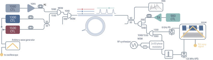
The experimental setup used in this work is depicted in Fig. S.1. We use a 1060 nm continuously tunable laser (CTL) amplified with an ytterbium-doped fiber amplifier (YDFA) to generate enough power at 283 THz to pump the microring to harness the resonator’s third-order nonlinearity. An on-chip power of about 150 mW is sufficient to reach a dissipative Kerr soliton (DKS) state in the fundamental transverse electric mode (TE) of the 23 µm \ceSi3N4 microring resonator. To help access this state, we use a 980 nm CTL amplified using a taper amplifier (TA) and set to be counterpropagative and cross-polarized relative to the main pump, so that this cooler pump only thermally stabilizes the resonator for adiabatic access to the DKS [34, 33] while minimizing potential nonlinear mixing with the main pump and/or the DKS. We use a combinations of wavelength demultiplexers (WDMs) at the input and output to avoid any injection of the cooler (main pump) into the main pump (cooler). The auxiliary and reference laser from the 1300 nm and 1550 nm CTLs are injected in the resonator by combining them with the main pump using a WDM, and are also set in the TE polarization. We tap 50 % of the output to probe the microcomb optical spectrum using an optical spectrum analyzer (OSA). We use another WDM at the other 50 % output to separate wavelengths close to 1100 nm, which are electro-optically (EO) modulated at GHz. The EO-generated sidebands of two adjacent DKS comb teeth fill the DKS repetition rate over EOcomb teeth, providing a measure of the DKS repetition rate GHz (the minus sign is configuration dependent and has been verified for our experiments), with the EOcomb beat note that can be detected by a 50 MHz avalanche photodiode (APD), similar to the methods presented in [35, 19]. The other WDM output is used to measure the beat note between the secondary color and the reference pump. Both signals are processed in the time domain using a high speed oscilloscope. We trigger the scope with the ramp signal used to sweep the piezo element of the CTL, obtaining a temporal trace which can be processed and converted into a spectrogram, enabling instantaneous frequency measurement. The calibration of this technique is further discussed in the next section.
Appendix S.2 Repetition rate and detuning calibrations from temporal traces
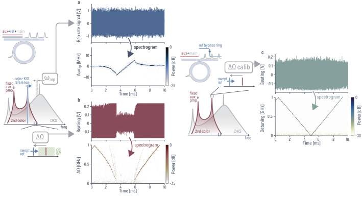
The EOcomb beat note , which directly lets us precisely characterize the repetition rate , and the reference pump and secondary-color beat are measured in the optical domain using a fast oscilloscope [Fig. S.2a-b], with a temporal resolution of 320 ps. The piezo element is swept at a 50 Hz rate around the detuning of interest. We record simultaneously the temporal trace of and , which we process using the scipy.signal.spectrogram python package [40]. We use a binning slice of points, allowing a frequency resolution of about 104 kHz. The fast Fourier transform (FFT) windowing is performed using a Hanning filter, with an overlap of points. We obtain a spectrogram with a clear peak for each time sample that correspond to either , from which we extract using the RF synthesizer frequency and the number of comb teeth as previously described, or .
However, the detuning needs to be calibrated accurately. We harness the fact that the frequency comb, if unsynchronized, can act as a local oscillator. To this extent, for each of the different measurements shown in Fig. 4, we proceed to calibrate the detuning by bypassing the microresonator with the reference and directly beating it with the closest secondary color comb tooth (i.e., no nonlinearity present since we bypass the ring, and hence no KIS) as shown in Fig. S.2c. Once again, we proceed to obtain the spectrogram from the temporal trace, from which we can calibrate the detuning over time, with a precise calibration of the zero-detuning (i.e. position of the secondary color comb tooth). We note that we obtain the absolute value of the detuning and need to process to change its sign based on the direction of the triangular waveform applied to the CTL piezo element. From knowledge of the CTL characteristics, we know that a high-to-low voltage results in a high-to-low frequency, hence the detuning is negative for times before the calibration frequency reaches zero, since the oscilloscope is triggered for positive slope with the piezo ramp signal.
Appendix S.3 Laser phase noise measurement
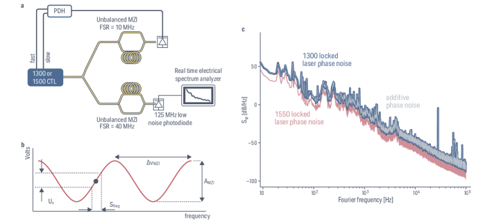
We lock the 1300 nm and 1500 nm CTLs using independent 10 MHz free spectral range (FSR) Mach-Zenhder interferometers (MZIs), and using a Pound-Drever-Hall technique allows us to actuate the current and piezo element of the laser (respectively fast and slow feebdack) to lock to the side of a fringe of the MZI [Fig. S.3]. To measure their respective phase noise, we use another MZI with a 40 MHz FSR. Setting the laser to be at a quadrature point of this MZI, we measure the residual MZI noise using a real time electrical spectum analyzer (RSA). Understanding the noise obtained from the MZI [Fig. S.3b], we can retrieve the frequency noise of the laser following:
with the voltage obtained from spectral measurement, where is the optical power in decibels normalized to 1 mW of the MZI noise at quadrature (i.e., in dBm), the spectrum analyzer impedance is assumed to be 50 , mV is the amplitude of the sinusoidal modulation with frequency of the MZI, and MHz is the free spectral range of the MZI used for noise measurement.
We can obtain the phase noise from the frequency noise, where the power is referenced to that of the carrier, namely, dBc/Hz:
When comparing the phase noise of the two locked lasers, the 1500 nm laser exhibits lower noise Fig. S.3. When accounting for additive noise since the two lasers are locked to independent MZIs, as the 1300 nm laser being more noisy than the 1500 nm laser, the noise of the 1300 nm laser is predominant. We therefore consider OFD of the 1300 nm laser noise when assessing the repetition rate noise under color-KIS.