11email: tonym@eso.org 22institutetext: Kavli Institute for Cosmological Physics, University of Chicago, Chicago, IL, 60637, USA 33institutetext: OHB Digital Connect, Weberstraße 21, D-55130 Mainz, Germany 44institutetext: Independent Consultant, Kirchgasse 4, D-61184 Karben, Germany 55institutetext: Institute of Theoretical Astrophysics, University of Oslo, P.O. Box 1029, Blindern, 0315 Oslo, Norway 66institutetext: Instituto de Astrofísica and Centro de Astro-Ingeniería, Facultad de Física, Pontificia Universidad Católica de Chile, Santiago, Chile 77institutetext: UK Astronomy Technology Centre, Royal Observatory Edinburgh, Blackford Hill, Edinburgh EH9 3HJ, UK 88institutetext: Department of Physics and Astronomy, University of Pennsylvania, 209 South 33rd Street, Philadelphia, PA, 19104, USA 99institutetext: Department of Technology Systems, University of Oslo, Gunnar Randars Vei 19, 2007 Kjeller, Norway 1010institutetext: Department of Physics, Cornell University, Ithaca, NY 14853, USA 1111institutetext: Department of Astronomy, Cornell University, Ithaca, NY 14853, USA 1212institutetext: INAF - Osservatorio Astronomico di Cagliari, 09047 Selargius, Italy 1313institutetext: European Southern Observatory, Alonso de Cordova 3107, Vitacura, Santiago, Chile 1414institutetext: Instituto de Astrofísica de Canarias (IAC), E-38205 La Laguna, Tenerife, Spain 1515institutetext: Universidad de La Laguna, Dpto. Astrofísica, E-38206 La Laguna, Tenerife, Spain 1616institutetext: Departamento de Física de la Tierra y de la Atmósfera e Instituto de Física de Partículas y del Cosmos (IPARCOS). Universidad Complutense de Madrid, Av. Complutense, s/n, 28040 Madrid, Spain
Design of the 50-meter Atacama Large Aperture Submm Telescope
Submillimeter and millimeter wavelengths can reveal a vast range of objects and phenomena that are either too cold, too distant, or too hot and energetic to be measured at visible wavelengths. For decades the astronomical community has highlighted the need for a large, high-throughput submm single dish that can map statistically significant portions of the sky with sufficient surface brightness sensitivity and angular and spectral resolution to probe truly representative source populations. The Atacama Large Aperture Submillimeter Telescope (AtLAST), with its 50-m aperture and maximal field of view, aims to be such a facility. We present here the full design concept for AtLAST, developed through an EU-funded project. Our design approach begins with a long lineage of submm telescopes, relies on calculations and simulations to realize the optics, and uses finite element analysis to optimize the mechanical structure and subsystems. The result is an innovative rocking chair design with six instrument bays, two of which are mounted on Nasmyth platforms. AtLAST will be capable of scanning and acceleration, and will feature a surface accuracy of m half wavefront error allowing observations up to GHz. Further, AtLAST will be a sustainable, visionary facility that will allow upgrades for decades to come. The demanding design requirements for AtLAST, set by transformative science goals, were met by combining novel concepts with lessons learned from past experience. While some aspects require further testing, prototyping, and field demonstrations, we estimate that the design will be construction-ready this decade.
Key Words.:
Telescopes – Astronomical instrumentation, methods and techniques – Instrumentation: high angular resolution – Submillimeter: general1 Introduction
The desire to understand the Universe and how we came to be—our cosmic origins—has been the driving force behind enormous scientific and technological progress in the field of astrophysics, leading to advances that have benefited society as a whole.111We note that by using the phrase cosmic origins, we do not mean to imply any formal association with any other ongoing effort, though synergies exist. While recent usage has included NASA’s Cosmic Origins Program (officially founded in 2011; see https://cor.gsfc.nasa.gov/news/news.php) and the film ALMA—In Search of Our Cosmic Origins (released in 2013; see https://www.eso.org/public/videos/eso1312a/), the term has long been in use by the community. For instance, it appears in the book title Our cosmic origins: from the Big Bang to the emergence of life and intelligence (Delsemme & de Duve, 1998), in the name of the Hubble Space Telescope’s Cosmic Origins Spectrograph (Bangert & Meyer, 1997), and in papers dating back to a century ago (Bongards, 1923; Millikan, 1925). Many of these advances require us to look beyond visible wavelengths, and to the millimeter and submillimeter in particular—into the so-called ‘Invisible Universe’ (Vallini et al., 2023). Our ambitious concept for a new large222Here we reserve the subjective term ‘large’ to refer to telescopes with primary mirrors meters in diameter. The exception to this is if the word ‘Large’ is part of the telescope name. aperture (50-meter), large field of view (2∘) single dish observatory with the capability to probe submillimeter and millimeter wavelengths ( mm) is motivated by equally ambitious and disruptive scientific goals: (i) to perform the deepest, widest (100-1000 deg2), and most complete imaging and spectroscopic surveys of the Galactic and extragalactic sky at a few arcsecond resolution, beating the confusion limits of previous experiments and resolving the cosmic infrared background (CIB); (ii) to study the morphology, kinematics, and chemistry of the multi-phase gas—as well as to study diffuse and low surface brightness gaseous structures—in the interstellar and circumgalactic media of our own and other galaxies, which can extend across angular scales of degrees and carry the imprints of the baryon cycle, by observing them through multiple molecular and atomic emission lines; (iii) to measure the thermodynamics and kinematics of the hot ionized gas in massive cosmic structures through the most sensitive subarcminute-resolution observations of the Sunyaev-Zeldovich (SZ) effect yet. The high surface brightness sensitivity, angular resolution, mapping speed and imaging dynamic range of the Atacama Large Aperture Submillimeter Telescope (AtLAST)333https://atlast-telescope.org/ concept result directly from the needs of delivering on these science cases. None of them can be achieved through current or funded future facilities. Further, they all require a high and dry site with excellent atmospheric transmission across the submm bands, and a telescope able to make the most of such conditions.
A brief introduction to AtLAST’s scientific goals was presented in Klaassen et al. (2020), who summarized the motivations and goals from the AtLAST design study proposal submitted to the European Commission in 2019. These science goals were further broadened and updated in Ramasawmy et al. (2022) after consultation with a wider user community. Presently, the science cases for AtLAST are examined in much greater detail through a large, concerted collection of dedicated papers (Booth et al. in prep; Cordiner et al. 2024 in prep; Di Mascolo et al. 2024 in prep; Klaassen et al. 2024 in prep; Lee et al. 2024 in prep; Liu et al. 2024 in prep; Orlowski-Scherer et al. 2024 in prep; van Kampen et al. 2024 in prep; Wedemeyer et al. 2024 in prep).444See https://open-research-europe.ec.europa.eu/collections/atlast. As a side note, the science case presented in Wedemeyer et al. 2024 in prep motivates Solar observations, which have been a key stretch goal for AtLAST since its inception; they now however constitute a compelling science driver in the project, and this in turn impacts a few of the design choices discussed here. As a benefit, the same ability to safely point the telescope towards the Sun will also improve the overall observing efficiency by obviating the need for a daily Sun avoidance shutdown.
AtLAST is conceived as a facility observatory that will serve a wide community of users for a long project lifetime ( years). It will be sited on the Llano de Chajnantor (Chajnantor plateau), approximately 5100 m above sea level in the Atacama Desert in northern Chile, which has long been a demonstrated site for mm and submm observations (see e.g. Radford & Holdaway, 1998). Commensurate with AtLAST’s broad and multifaceted science community, our science goals drive the necessity for a large receiver cabin able to host multiple instruments that can access its large field of view and that can be upgraded throughout the lifetime of the observatory. In order to make the best use of sudden changes in weather conditions on the Llano de Chajnantor, the telescope operators need to be able to switch quickly (within a few minutes) between different instruments. This of course needs to be a safe task to carry out during both night and daytime operations.
The design concepts of AtLAST build upon nearly 50 years of experience with submillimeter observations and observatories, from pioneering projects like the Caltech Submillimeter Observatory (CSO; Leighton, 1977; Phillips, 1988), the Swedish-ESO Submillimeter Telescope (SEST; Booth et al., 1987, 1989), and the James Clerk Maxwell Telescope (JCMT; Hills, 1988, 1990), to the Atacama Large Millimeter/Submillimeter Array (ALMA). AtLAST will be an excellent and much needed complement for ALMA. Along with upgrades to ALMA itself (Carpenter et al., 2019, 2023), AtLAST will contribute to keeping ALMA relevant for the foreseeable future: it will provide new targets and positions for high-resolution follow-up campaigns and offer the short uv baseline coverage needed for single-dish and interferometric data combination at high frequencies (e.g. Plunkett et al. 2023).
The concept of a large and truly submm single dish itself—reaching frequencies GHz—has a long history, dating back a number of decades (Herter et al., 2004; Giovanelli et al., 2006; Kawabe et al., 2016; Testi et al., 2016; Lou et al., 2020), and has evolved and matured over this time. A key step in this process is that we are now poised to deliver a design with truly transformative qualities, from the large field of view (FoV) and optical throughput (étendue) that will ultimately allow megapixel-scale submm cameras, to the power generation and energy storage and recuperation systems necessary to carry out the project sustainably, to the metrology systems required to keep the beam performance exceptionally stable in a system not sheltered by a dome.
The climate-change concerns and fuel price vulnerability faced by modern day society have informed the development of the AtLAST concept, which has incorporated from the start a dedicated environmental sustainability study (as noted in, e.g., Klaassen et al., 2020). The AtLAST project has driven new research to devise an energy system that not only needs to accommodate the high demand of the telescope and its instrumentation through the most environmentally sustainable off-grid energy generation and storage solutions, but also provide a constant and reliable supply across the full diurnal and seasonal cycles (Viole et al., 2023b, 2024). This work is already motivating other astronomical research infrastructures to either emulate these solutions, or produce similar alternatives, and so we hope that they will have a wide impact on astronomy and throughout society as a whole. Building on combined approaches relying on previous studies from energy communities in the European Union (e.g. the Renaissance Project555https://www.renaissance-h2020.eu/.), the AtLAST project is considering the objectives of the local community and local stakeholders in the San Pedro de Atacama region in the design of its renewable energy system, contributing to the just and equitable use of energy resources in the area (Valenzuela-Venegas et al., 2023).
In this work, we present for the first time the full conceptual antenna design for AtLAST, developed during the first three years of the EU-funded design study (see Acknowledgments for further details) and of which Mroczkowski et al. (2023) presented a brief update and overview. This paper is organized as follows. In Sect. 2, we describe the overall motivation and scope of the AtLAST design study, and discuss the key design requirements. In Sect. 3, we describe the final optical design and how it was optimized. In Sect. 4, we present the antenna structure and key results of the finite element modeling and analysis. In Sect. 5, we discuss and show how the optical performance, and the pointing and surface accuracy in particular, are achieved. In Sect. 6, we present the features of the receiver cabin and concepts for instrument installation and access. And finally, in Sect. 7, we provide our conclusions and discuss the next steps for the design and the AtLAST project. As a convenience to the reader, we list the acronyms and abbreviations we use in Table 6 of Appendix A.
2 The AtLAST Design Study
The key design goals of AtLAST are perhaps deceptively simple: we aim to build a facility with a large collecting area, high resolution, and the ability to observe up to frequencies THz. Further, in order to serve a multitude of science goals, this facility must feature a large receiver cabin capable of housing multiple massive instruments. The space allocated for each receiver is large, as two of them must ultimately be able to fill a field of view roughly two orders of magnitude larger than any previous large submm single dish has had, while the mounting points for the smaller receivers must also be capable of hosting instruments that fill a significant portion of the field of view.
While the AtLAST concept is straightforward, no such design had previously been worked out in detail. To this end, a project including the telescope design — structural engineering, optical design, finite element analysis, and end-to-end modeling — was proposed to the European Union’s Horizon 2020 research and innovation program, and in March 2020 it was awarded. While the project officially commenced a year later, in March 2021, the telescope design work began in earnest in July 2020 with the optical design considerations later summarized in Hills (2021).
2.1 Design approach
As described in Sect. 3 and further detailed in Gallardo et al. 2024 (in prep), the AtLAST optical design goal was to maximize the field of view while minimizing the mass (for a fixed 50 m diameter primary mirror). This in turn drives many of the structural choices for the antenna.
The overall design approach was iterative, as many of the design choices cannot be treated as independent. Feedback from one step often led to reconsidering the previous step, until convergence was reached. Our structural design approach began from the optical layout and, building from experience with previous design, followed the principles of homologous support (described in Baars & Kärcher, 2018) for the primary mirror support structure to converge on a preliminary concept for the overall antenna structure. From there, we produce a model for the telescope (Sect. 4.2), which is then iterated through finite element modeling (Sect. 4.3) until converging on a working structural design for the telescope. Further tests and modeling are then used to assess the telescope design properties and, if necessary, adjust the structural design.
2.2 Design requirements
The key science drivers of AtLAST lead to a set of demanding observational capabilities, which in turn set most of our key design requirements; a number of other requirements are also set by the demanding environment or the desire to facilitate maintenance and operations. The overall design goals and requirements for AtLAST were presented in Klaassen et al. (2020). We provide an updated version of the key technical requirements in Table 6 in order to guide the general discussion in this work. Of the requirements in Table 6, the following are key in driving the telescope design.
| Parameter | Value |
|---|---|
| Wavelength () range | 0.3-10 mm |
| Primary Mirror Diameter | 50 m |
| Field of View (FoV) | 2∘ (1∘)††footnotemark: † |
| Number of Instruments | |
| Effective Focal Length | m |
| Number of Mirrors | |
| Number of Segments | |
| Sizes of Segments | m2 |
| Total Collecting Area | m2 |
| Optical surface accuracy | 20-25 m |
| Surface Coating | similar to ALMA |
| Optical Design | Cassegrain-Nasmyth |
| Description of Active Optics | active surface with metrology |
| Actuator Precision | m |
| Pointing accuracy | 2″ |
| Scan Speed | 3 |
| Acceleration | 1 |
| Elevation (EL) range | |
| Azimuthal (AZ) range | |
| Mount Type | AZ-EL |
| Support Structure Material | steel & invar |
2.2.1 Wavelength range and Surface Accuracy
AtLAST aims to cover approximately the same wavelength range ( mm, GHz) as ALMA, with the lower end of the frequency range extended down to 30 GHz as requested by some of the key science goals, such as those relying on AtLAST’s complementarity with current and planned Cosmic Microwave Background (CMB) survey experiments (albeit at higher resolution, and source sensitivity).
The high frequency goal for AtLAST drives not only the site selection, but also the surface accuracy, or half wavefront error, which limits the aperture efficiency at the highest attainable frequency. Here, a relative aperture efficiency of 50% that of the lowest frequencies is generally considered acceptable. As a first approximation in this work, we use the Ruze (1966) formula to estimate what surface accuracy is required to achieve a sufficiently high aperture efficiency. We note that our surface accuracy goal of 20 m half wavefront error (Table 6) is comparable to that achieved by ALMA, which has been shown to be sufficient for observations up to GHz, making use of the highest frequency atmospheric windows available from Llano de Chajnantor. The surface accuracy goal considers the errors caused by surface deformations on small scales (2-5 m), while we note that the large scale deformations ( m) of the primary reflector will be compensated by an active surface working in a closed-loop mode with a sensor system as well as by the pointing model. On the Chajnantor plateau, the best observing conditions are typically available at night and early mornings (e.g. Cortés et al., 2020; Gómez Toribio et al., 2021; Morris et al., 2022), and so we refer to 20 m as our nighttime surface accuracy goal. We also set a strict requirement of 30 m half wavefront error for daytime observations, when thermal effects are worse and both wind speed and precipitable water vapor (PWV) are generally higher.
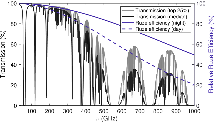
In Fig. 1, we show the results of our Ruze efficiency calculation, arbitrarily renormalized to 100% at the lowest frequency, for both the 20 m nighttime surface accuracy goal and for the 30 m daytime surface accuracy expectation. We compare this to the atmospheric transmission, computed using the am code (Paine, 2018), to illustrate the case that the telescope surface accuracy in the best quartile conditions will not be the limiting factor for high frequency observations. In short, the losses due to Ruze scattering can be expected to be subdominant to the losses due to atmospheric transmission. Gallardo et al. (in prep) and Puddu et al. (in prep) will provide more details for the optics, including calculations of the overall optical performance as well as a full physical optics calculation of the beam and cross-polarization performance. The nuances and limitations of applying the Ruze formula are discussed further in Sect. 5.1.
2.2.2 Pointing accuracy
The pointing accuracy is perhaps one of the most challenging aspects for the AtLAST design, due to its large surface area, high frequency science drivers, and unsheltered, domeless structure. Unlike optical telescopes, submm telescopes cannot generally check their pointing direction with a dedicated camera that can resolve the current pointing direction – although star cameras can be installed, their light path does not use the same mirrors and so will not reflect the full pointing errors. Therefore the initial blind pointing error must be in the range of the width of the main lobe of the submm telescope while the tracking and offset pointing accuracy need to be even better by a factor . The required blind pointing accuracy of AtLAST can be derived by considering the full width at half maximum (FWHM) of the first maximum of an Airy disk for the minimum wavelength of 350 m and an aperture diameter of 50 m. The resulting FWHM value can be calculated to be approximately . It is important to note that for observing modes that do not use large arrays, such as VLBI, any pointing corrections need to be carried out in real time.
We set a requirement of 2″ for the pointing accuracy, driven by the demonstrated results using astronomical pointing models for essentially all (sub-)mm telescopes yet built. For instance, the 64-m Sardinia Radio Telescope (SRT; Prandoni et al., 2017), which will observe at frequencies up to 116 GHz, achieves 13″ uncorrected mechanical pointing accuracy, but has demonstrated 2″ pointing accuracy when corrected with a standard astronomical pointing model. Similarly, using the 100-m Green Bank Telescope (GBT), White et al. (2022) demonstrated they could correct the root mean square (RMS) error to 12 accuracy using an astrometrically corrected pointing model. This is a dramatic improvement over the previous pointing model corrected value of 28 (Prestage et al., 2009). The GBT also observes up to 116 GHz, where it has a beam FWHM of 85, and was designed to achieve an uncorrected pointing accuracy . Both examples highlight the commendable levels of improvement (by factors of better) attainable with standard astronomical pointing models applied to large aperture telescopes.
To achieve a pointing accuracy of for AtLAST, we expect that a static pointing error correction model combined with closed-loop control compensation techniques (e.g., flexible body control, Baars & Kärcher 2018) will need to be implemented, or alternatively, a new approach using machine learning algorithms that can include sensor data and more factors needs to be developed, such as that recently tested by Nyheim et al. (2024). We describe our approach to achieving the pointing accuracy requirement in Sect. 5.4.
2.2.3 Primary Mirror Diameter
Our goal is to build AtLAST with a 50-meter aperture, the choice of which is driven by both resolution and sensitivity, which in turn sets a requirement for a large collecting area. While larger aperture sizes may in principle be achievable (see e.g. Kärcher & Baars, 2014), we found 50 meters to be the minimum size to fully resolve the Poissonian cosmic infrared background (CIB) at our highest frequencies, allowing the emission from sources to be distinguished rather than limited by confusion (see e.g. van Kampen et al., 2024 in prep). Similarly, we can expect the confusion noise in observations of the thermal Sunyaev-Zeldovich effect to be a factor of lower for AtLAST than it was for the Planck satellite (see e.g. Di Mascolo et al., 2024 in prep), allowing much better constraints on cluster astrophysics and cosmology.
A more stringent lower limit on the aperture size is also set by the desire to provide sufficient overlap in Fourier space with the ALMA 12-meter Array for data combination that results in high spatial fidelity imaging at even smaller scales than those that will be probed by AtLAST alone. As shown in, for example,Frayer (2017) and Plunkett et al. (2023), the minimum requirement for reliable data combination is that the single dish be the array element’s diameter. For ALMA this would be 36 meters. Regardless, our 50-m goal ensures we will be able to achieve more than sufficient overlap in Fourier space with both ALMA and ngVLA, as well as any high frequency upgrades to the Square Kilometer Array (SKA).777See for example SKA Memo 20-01.
2.2.4 Field of View (FoV)
The large field of view of AtLAST is one of the key drivers for the optical design (Sect. 3) and places significant demands on the overall antenna structure (Sect. 4), ultimately driving us to the choice of a rocking chair design for the elevation structure (described in Sect. 4.1).
The field of view of an imaging submm single dish telescope like AtLAST determines two key parameters: the mapping speed, which scales as the number of beams on sky, and the largest angular scale that can be recovered in the observation after removal of the atmospheric signal. Following Cordes (2008) and Wilson et al. (2013), we define a figure of merit (FoM) for survey mapping speed as
| (1) |
Here is an efficiency factor which can be assumed to be approximately the same for telescopes with similar surface accuracy, is the number of fields of view probed simultaneously, is the solid angle of the field of view, is the bandwidth, is the effective area, is the Boltzmann constant, and is the system noise temperature. For both AtLAST and ALMA, we set ; ALMA is single beam, and has not been upgraded to host focal plane arrays, while we consider AtLAST to have a single, large field of view. The ratio of the collecting area of AtLAST to that of ALMA is 0.34 assuming 50 ALMA 12-m antennas.888We note that the current minimum number of antennas for ALMA 12-meter Array observations is 43 (Remijan et al., 2019). Therefore, assuming the same bandwidth, efficiency, and , the advantage for AtLAST lies in . For instance, at 850 m we expect the recoverable999The recoverable FoV is greater than or equal to the diffraction limited FoV of the telescope itself, and depends on optical corrections in the instrument. FoV of AtLAST to be in diameter (see Mroczkowski et al. 2023 and Gallardo et al. in prep), yielding a and . While we can expect an aperture efficiency comparable to ALMA (see Sect. 2.2.1), further improvements to this figure of merit can be realized through, for example, wider receiver bandwidth , instruments that allow simultaneous observations in multiple bands, or by achieving lower receiver noise temperatures, which in turn would result in lower (see e.g. Carpenter et al., 2023, who note the receiver noise temperatures in all current ALMA bands are factors higher than the quantum noise limit).
2.2.5 Scanning Speed and Acceleration
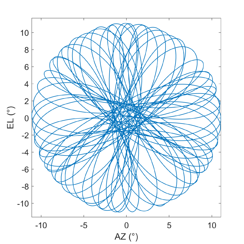
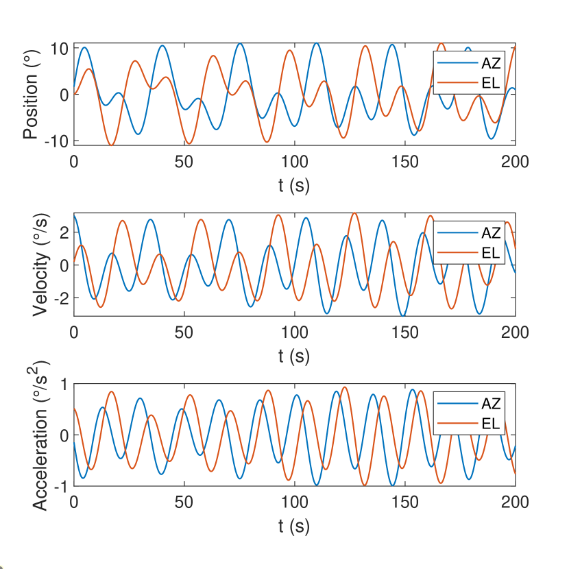
As a user facility, AtLAST will support a wide range of scanning patterns similar to those already implemented in several other telescopes. These include azimuthal scans at constant elevation (e.g. Swetz et al., 2011), Lissajous daisy scans (see e.g., Fig. 2), simple daisy scans, classic Lissajous scans, and several tracking modes, such as sidereal tracking or more rapid tracking of solar system objects like comets, asteroids, and near Earth objects. Of these, we expect those placing the strongest demands on the structure and antenna drives will be the fast azimuthal survey scans at constant elevation and the more compact Lissajous Daisy scans (see e.g. Fig. 12). We note that both the azimuthal and elevation scan speeds will be limited in general to , while the accelerations will be (Table 6). As a precaution, the maximum allowed speed linearly declines from to in the last of the AZ/EL ranges (i.e. , , and ).
For single dish observations, recovery of faint continuum emission as well as faint line emission whenever the line frequency is not known a priori depends critically on the ability to modulate the astronomical signal faster than the atmospheric signal (van Marrewijk et al., 2024). This drives the requirement for AtLAST to scan quickly compared to both motion of the atmosphere (wind) and evolution of atmospheric substructures, while the operational requirement to keep observational overheads to a minimum drives the need for rapid acceleration.
At the same time, the noise power spectrum of a bolometer or heterodyne receiver generally has a component of ‘pink’ noise. This noise, generally related to drifts in gain and thermal properties of the instrument, is higher at lower temporal frequencies (on longer timescales) than at higher ones (on shorter timescales). In the case of phase-incoherent detectors such as bolometers or kinetic inductance detectors, this is often referred to as noise (e.g. Mather, 1982), while for phase-coherent heterodyne instruments this is usually measured as the Allan variance (e.g. Yagoubov et al., 2020). In practice, this also drives the requirement to scan quickly enough that the astronomical signal is out of the pink noise-dominated portion of the instrument’s noise power spectrum, and generally in a Gaussian white noise (i.e. featuring a more flat power spectrum) portion, where the amplitude of the total cumulative noise is lower (see the discussion in van Marrewijk et al., 2024).
Recently, using data from the Atacama Cosmology Telescope (ACT) and sophisticated modeling of the atmospheric turbulence and time-evolution, Morris et al. (2022) showed that the optimal scan speed is that which keeps the atmospheric signal relatively stationary in the time domain, facilitating for instance filtering and common mode subtraction (again, see van Marrewijk et al., 2024). For the typical scale height of the atmosphere above Llano de Chajnantor this implies an average scan speed of 1.5 when scanning in the same direction as the wind. In order to include a margin for faster wind conditions and the elevation dependence, we thus chose a scan speed requirement of 3. Further, in order to be able to map small regions and achieve high scanning speeds quickly, we chose an acceleration limit of 1. A representative Lissajous Daisy scanning pattern for AtLAST, which attains the maximum allowed acceleration and speed, is shown in Fig. 2.
The choices of maximum acceleration and scan speed were also guided by previous experience with large single dish telescopes, and have implications for the stiffness and resonances of the structure, which we examine through finite element analysis and modeling. We discuss this further in Sect. 4.3.
2.2.6 Sustainability
While not a formal requirement of the telescope design itself, a crucial goal and driving philosophy in the AtLAST design study has been to maximize the environmental as well as social sustainability of the project. This is in line with the recommendation of, for example, the United Nations Intergovernmental Panel on Climate Change (IPCC; see e.g. Shukla et al., 2022), who recommend achieving carbon neutrality before 2050. To this end, the AtLAST design study included a crucial work package on delivering solutions for sustainably powering the facility (Viole et al., 2023b, 2024). The two prospective sites101010See the AtLAST site selection criteria report. being considered for AtLAST, both of which at an altitude of 5050 meters above sea level in the Atacama Desert in Northern Chile, are not connected to the power grid. While a number of astronomical projects in the region are now implementing solar arrays that will vastly reduce their reliance on carbon-based fuels, AtLAST is the first, to our knowledge, designed to be fully powered by renewable energy sources (RES) from its inception.
AtLAST is also among the first astronomical design studies to publish a life cycle assessment of its possible energy system setups, which are described in Sect. 4.4. Viole et al. (2023a, 2024) found systems relying on large shares of solar photovoltaic generation to have significantly lower carbon footprints over the system’s life cycle compared to today’s diesel generators, while requiring more water and metal resource use. Further work is needed to also include the telescope itself within the scope of such an environmental assessment, as proposed by Knödlseder et al. (2022). Valenzuela-Venegas et al. (2023) have also addressed social sustainability and energy justice through including the energy system preferences of stakeholders of the nearby community of San Pedro de Atacama in the design process.
In addition to the sustainability study mentioned above, the telescope itself will implement innovative concepts to reduce its power demand. As one of the design drivers is fast scanning and acceleration (Table 6 and Sect. 2.2.5) of a massive structure, it follows that the energy required for such motions is also high. We therefore developed an energy recuperation system concept based on supercapacitors, which allow regenerative braking and thus drastically improve the energy efficiency of the telescope’s motion. To our knowledge, it is the first time that regenerative braking is implemented in a telescope design.
We provide an overview of the power demands and the energy recuperation system in Sect. 4.4. We note that the full description of the energy recuperation system will follow in Kiselev et al. (in prep), while the concepts for power generation and energy storage were presented in Viole et al. (2023b, 2024).
3 AtLAST Antenna Optics
The optical design for AtLAST takes a Ritchey-Chrétien hybrid Cassegrain/Nasmyth approach, with the primary and secondary mirrors (M1 and M2, respectively) located on axis, and a flat, folding tertiary mirror (M3)111111Here we mean ‘folding’ in optical sense, that it is flat and does not change the focal length, hence it ‘folds’ the beam. The tertiary mirror does not fold mechanically. that allows fast instrument selection. Like many of the current generation of submm and mm telescopes that are smaller (generally meter) than AtLAST but achieve high throughputs (FoV times collecting area) and correspondingly high mapping speeds, AtLAST features fast optics, with a primary mirror focal ratio of , and a focal ratio at the instrument of . Here we refer to what is normally termed the ‘focal plane’ as the ‘focal surface’, in recognition of its significant curvature.
A focal ratio of was chosen both to keep the physical scale of the focal surface as small as reasonably possible and to maximize compatibility with existing receiver designs from, for example, the Simons Observatory (SO; Zhu et al., 2021; Bhandarkar et al., 2022), CCAT (Vavagiakis et al., 2018), and CMB-S4 (Gallardo et al., 2022, 2024) with relatively few changes. In the next sections, we describe the evolution of the design, followed by a description of the final optical design for AtLAST.
3.1 Evolution of the optical design
We initially considered several approaches for the optical design before making a down-selection, as detailed in AtLAST Memo #1 (Hills, 2021). These included a Cassegrain, a Nasmyth, a three-mirror symmetric approach similar to that taken by the Vera Rubin Observatory, and a three-mirror off-axis approach inspired in part by the design of the 100-m Green Bank Telescope (GBT; White et al. 2022), which has 2 mirrors, and the CMB-S4 Three Mirror Anastigmatic design (TMA; Padin, 2018; Gallardo et al., 2024).
Due to the size, mass, and overall feasibility considerations outlined in the memo, we converged on a Ritchey-Chrétien design which optimizes the compactness of the structure while achieving a wide field of view. For comparison, AtLAST’s geometric FoV is roughly larger than that of the 50-meter Large Millimeter Telescope/Gran Telescopio Millimetrico Alfonso Serrano (LMT/GTM; Kärcher & Baars, 2000). We note that historically, though the Ritchey-Chrétien design was developed in the early 1900’s for visible wavelength telescopes, it was developed essentially for the same reason AtLAST chose to adopt it now. The Ritchey-Chrétien optical design reduces coma and maximizes the FoV, allowing much larger images to be taken than with traditional parabolic reflectors (Wilson, 1996). In this sense, AtLAST is among the first large submm telescopes to be designed specifically for wide field imaging.
3.2 The final optical design
Fig. 3 presents AtLAST’s optical layout, and the optical parameters are summarized in Table 2. Here, the back focal distance is defined as the distance along the optical path from the central opening in the primary mirror surface to the center of the focal surface.
| Parameter | Value | Units |
|---|---|---|
| Primary Mirror (M1) Diameter | 50.0 | m |
| Primary Focal Length | 17.5 | m |
| Secondary Mirror (M2) Diameter | 12.0 | m |
| Back focal distance | 14.0 | m |
| Tertiary Mirror (M3) Diameter | m | |
| Focal Surface (FS) Diameter | 4.7 | m |
The AtLAST optical configuration—in particular, the short focal length coupled with a folding M3—is what enables the geometric FoV. The rotating M3 allows AtLAST to select among at least six large instruments (Section 6.2), exceeding the initial minimum requirements we set for AtLAST (Table 6). This design choice also reduces the number of mirrors to fewer than four, which adds the advantage of reducing the optical loading in the instrumentation. The full geometric optical design will be presented in detail by Gallardo et al. (in prep), while Puddu et al. (in prep) will show a detailed analysis of the physical optics performance, including calculations of the effects of diffraction from the gaps in the primary mirror and from scattering off of the secondary mirror support structure.
We must note here that the geometric FoV of the design does not ensure a diffraction-limited FoV for the full range of frequencies AtLAST will cover. Two-mirror telescopes like AtLAST are in general able to cancel two of the three first-order optical aberrations, leaving astigmatism uncorrected.121212In this context, we consider AtLAST optically to be a two-mirror design. The folding tertiary mirror (M3) of AtLAST is flat, and therefore does not enter the considerations for the correction of aberrations. Options for a shaped M3 were considered early in the AtLAST design study, but were found to introduce an unwanted elevation dependence in the beam shape. The presence of astigmatism limits the diffraction-limited FoV, in the absence of corrective optics. The result can be seen in Fig. 4, which shows the uncorrected Strehl ratios for several representative frequencies. A Strehl ratio is considered diffraction-limited, so it is clear that without correction the useful FoV AtLAST would be quite limited at high frequencies.
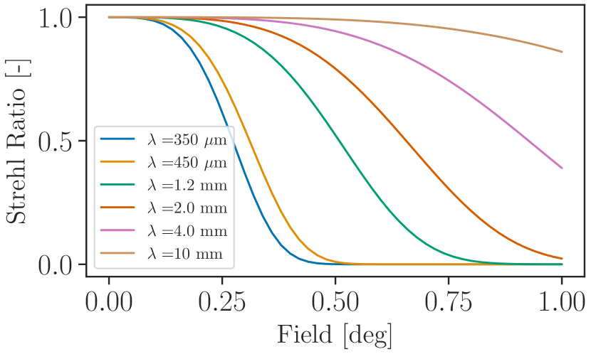
Fortunately, it is possible to correct astigmatism within the science instruments themselves by introducing an asymmetric biconic optical element (e.g. a lens) in the optical chain. The optimal place to insert this asymmetric optical element is the image of the entrance aperture (Lyot stop), or a neighboring optical surface. This approach has been developed and presented elsewhere (Lou et al., 2020; Gallardo et al., 2022; Huber et al., 2022), and has been implemented in various mm/submm instruments (e.g. Dicker et al., 2018; Parshley et al., 2018). Mroczkowski et al. (2023) showed preliminary results with corrective optics, while Gallardo et al. (in prep) will present full design concepts for optics within the instrument that correct much of the astigmatism and help recover significant portions of the geometric field of view of the telescope.
4 AtLAST Antenna Structure
In this section, we discuss the overall antenna structure and how it achieves the design requirements from an observer’s perspective. Reichert et al. 2024 (in prep) will present the final design concept for AtLAST from an engineering perspective, along with a more complete discussion of the structure, finite element analysis, and end-to-end modeling. We summarize the salient points with the astronomical observer user community in mind here.
4.1 Structural design approach
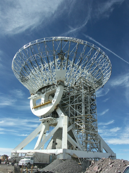
The final choice for the optical layout, as described in this work in Sect. 3.2 and in Hills (2021), had a significant impact on the structural and mechanical design of the telescope mount. The required space in the receiver cabin for the science instruments of AtLAST (discussed in Sect. 6.2) is significantly larger than that of any previous or existing mm/submm telescope. As a consequence, it was no longer possible to stick to the classical bearing concepts used for other altitude-azimuth mounted mm/submm telescopes, with a wheel-on-track type azimuth axis and the elevation axis defined by two roller bearings (as used by, for instance, the 50-meter LMT/GTM shown in Fig. 5).
An innovative solution was found by switching to a rocking chair design for the elevation structure, similar to those currently used for extremely large optical telescopes (e.g. the Extremely Large Telescope, ELT; Spyromilio, 2007; Tamai & Spyromilio, 2014). Large openings in the center of the elevation wheel provide ample space for two Nasmyth platforms, which in turn support two large science instruments that remain stationary in elevation (see left upper panel of Fig. 6). Four smaller receivers are attached to the top of the elevation wheel structure and rotate together in elevation (discussed in detail in Sect. 6). The design of the backup structure follows the so-called isostatic four-point support principle, which was introduced in the 1970s for the design of large radio reflectors (Baars & Kärcher, 2018). The principle introduces homology into the design, avoids first-order astigmatism and coma, and reduces the relative gravitational deformations of the reflector by an order of magnitude. The proportions of the elevation wheel are adapted to the four points of the backup structure (see upper right and lower central panel of Fig. 6), which ensures isostatic decoupling between the backup structure and the elevation wheel (Kärcher & Baars, 2014; Baars & Kärcher, 2018).
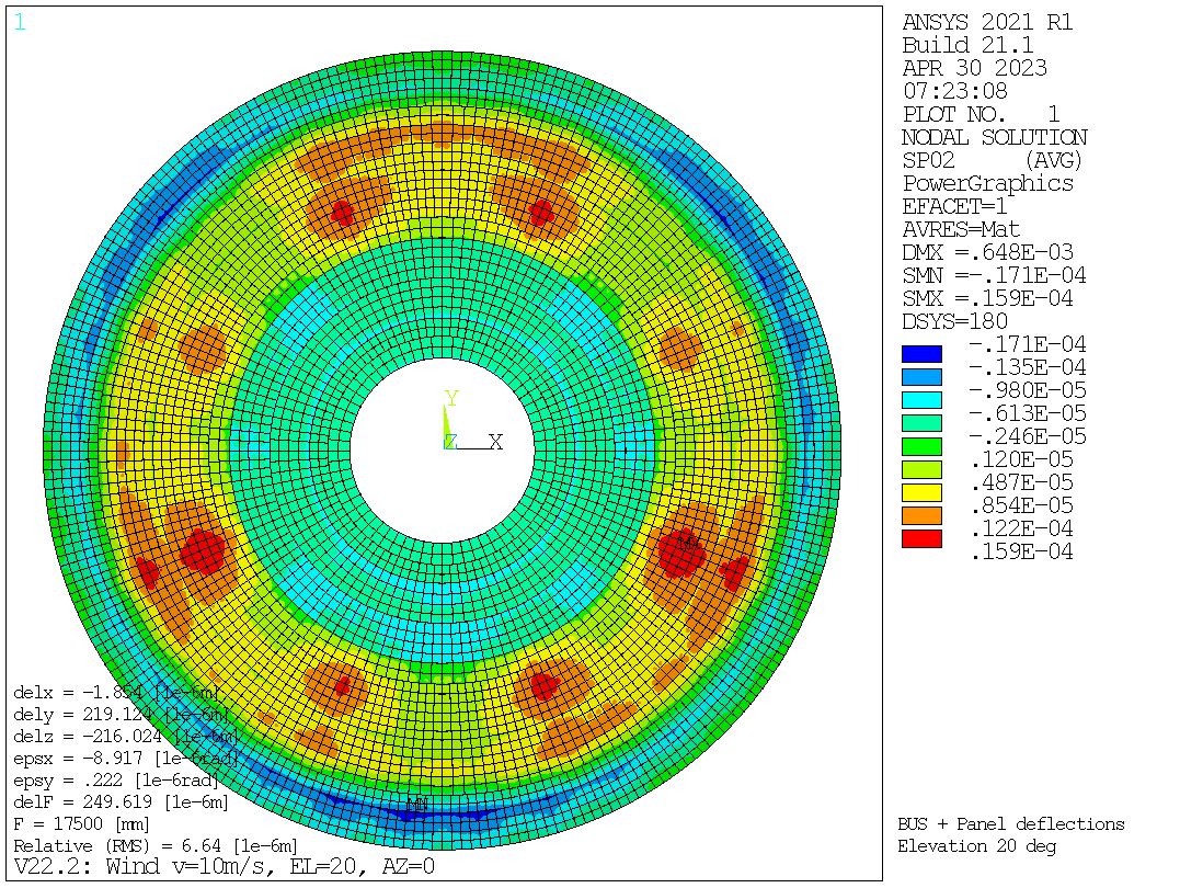
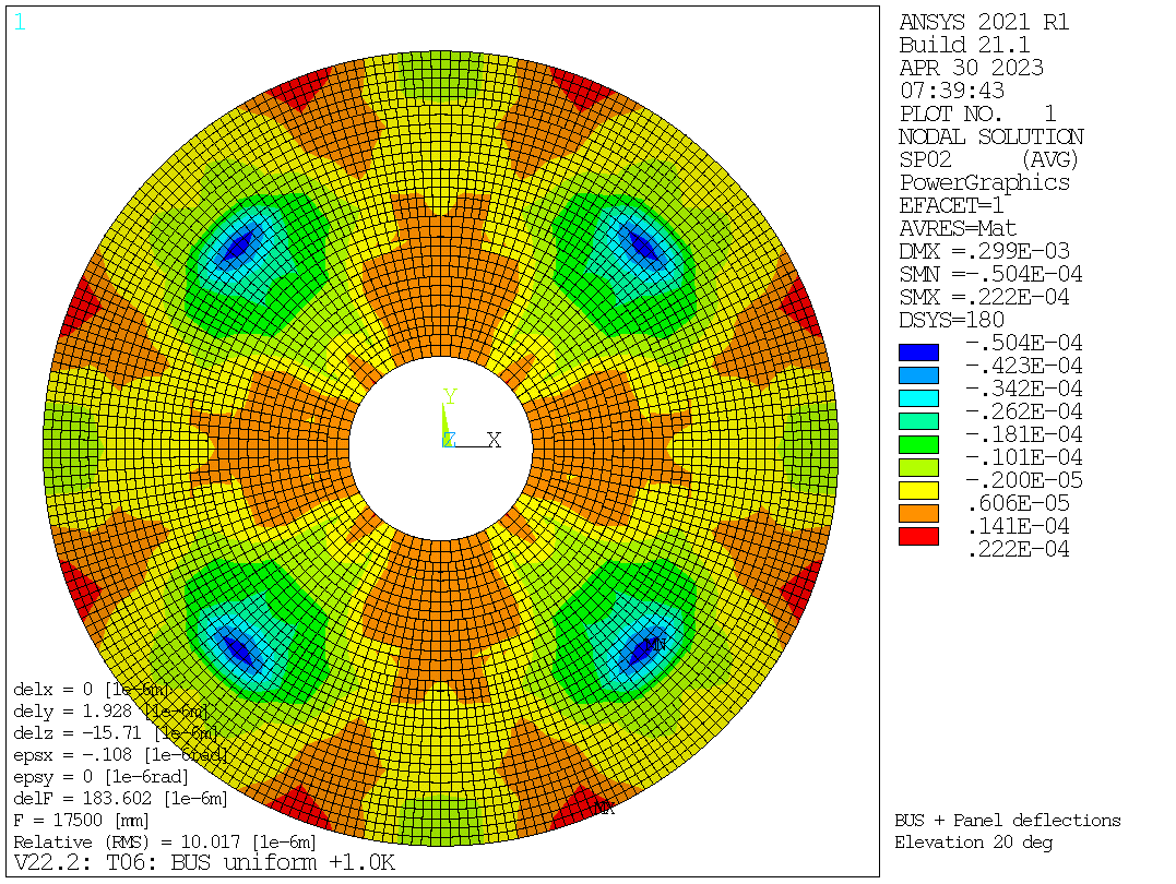
We verify the intended deformation behavior through finite element analysis (FEA) of the concept described in Sect. 5, and provide detailed outputs of the FEA in Appendix B. The final accuracy of the passive reflector under gravity load is better than than 200 m RMS over the whole range of motion, from 20∘ to 90∘ in elevation. The deformations are very repeatable and can be largely corrected using look-up tables. Major effects occur only in small areas around the four-point supports. The steady-state type deformations under 10 m s-1 wind are less than 25 m RMS, mainly due to strong astigmatism. Active corrections are only required for very low order Zernike polynomials. The dynamic wind effects on the reflector shape are an order of magnitude smaller than the steady state effects and are only relevant for pointing. Deformations due to temperature effects are minimized by external cladding and forced ventilation inside the backup structure and the elevation wheel, similar to the Institut de radioastronomie millimétrique 30-meter Telescope (IRAM 30-m; Baars et al. 1987) and the 50-m LMT/GTM (Kärcher & Baars, 2000). Temperature sensors inside the backup structure and the rocking-chair can be used for closed-loop corrections to improve the response to thermal deformations.
4.2 AtLAST Computer Aided Design (CAD) Model
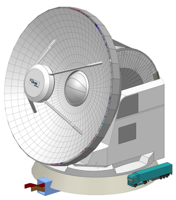
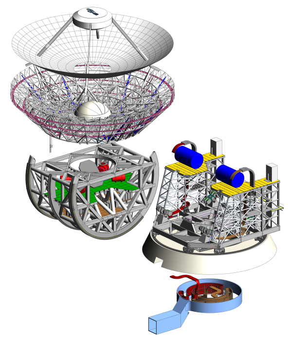
The full computer aided design (CAD) model for AtLAST is shown in Fig. 7, with an exploded view in the right panel in order to show how several of the major assemblies come together. In Fig. 7, one can see the 50-m primary mirror and 12-m secondary mirror, which are carried along with the rocking chair elevation rotating structure (Sect. 4.3.2). The rocking chair is cradled on the azimuthal support structure, carried by two nested azimuthal tracks. Also carried by the azimuthal support are the Nasmyth platforms and the housing for the receiver cabin discussed in Sect. 6.2. The light blue shaded assembly, representing the cable wrap and power housing, will be located underground. Mass estimates for the major components as well as the receivers, discussed in Sect. 6, are provided in Table 3.
| Structure or Component | Mass (tons) |
|---|---|
| Telescope structure total | 4400 |
| Azimuthal structure (w/o instr.) | 1390 |
| Elevation rotating structure (incl. ballast) | 3000 |
| main reflector, backup structure, subreflector | 1080 |
| Wheel load AZ. wheel | 200 |
| On-elevation-axis (Nasmyth) instruments | 230 |
| Off-elevation-axis (Cassegrain) instruments | 410 |
4.3 AtLAST Finite Element Modeling
The key drivers for the structural design of the AtLAST telescope are the surface accuracy and the blind pointing accuracy requirements. As is customary in antenna design, these requirements were distilled into error budgets for each engineering consideration. A finite element model was built and used to verify the budget allocations of the passive structure due to environmental loads (gravity, wind, and temperature). Here we use the term ‘passive structure’ to refer to that before any active compensation of unwanted deformations by a closed-loop control system. The approach chosen for the structural telescope design is to use cost efficient materials such as steel and aluminum for the large scale structures, and to use materials with optimized mechanical properties such as Carbon Fiber Reinforced Plastics (CFRP) only when compensation by a metrology system is not possible or practical. At the current state, the primary reflector panel segment and the secondary reflector require the use of CFRP to reduce thermal deformations and weight.
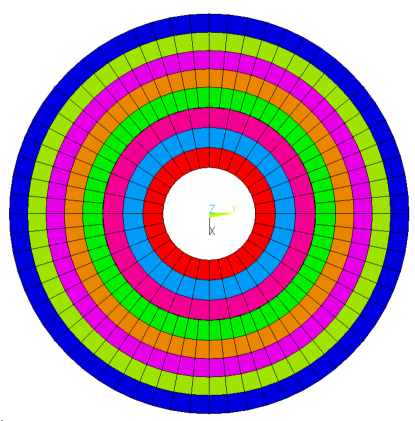
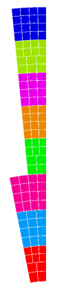
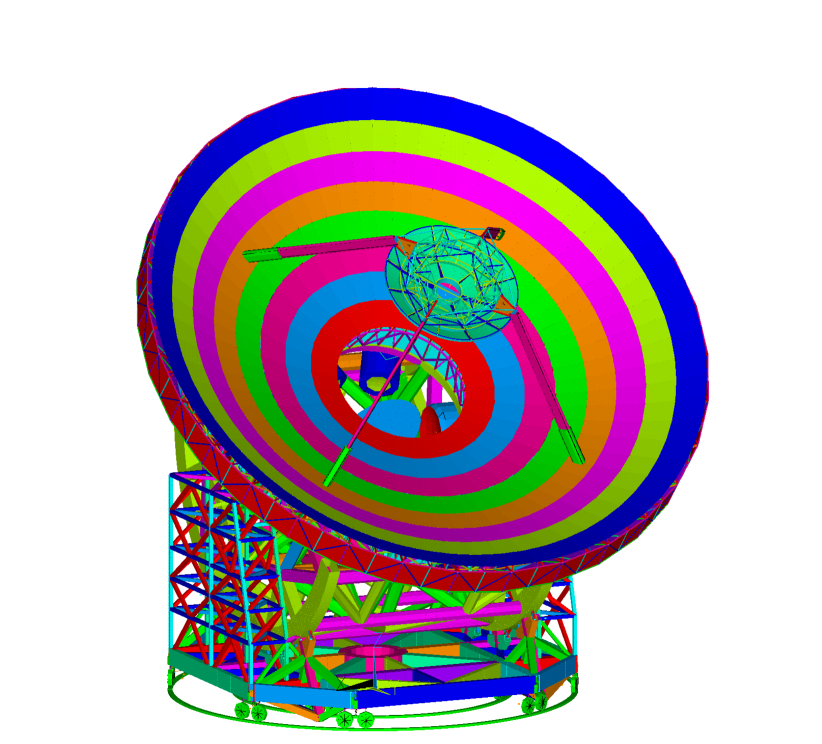
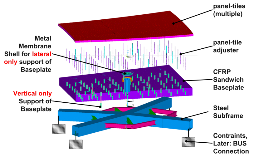
For the modeling and the evaluation, we used the Ansys 2021 R1 software suite.131313https://www.ansys.com/ The finite element analysis was done using two analysis submodels. The first is the overall telescope model (see Fig. 8) comprising the major load carrying structural elements with simplified panel segments to analyze error contributors allocated to the primary backup structure and overall structure. The second is a detailed model of the panel segments (see Fig. 9) that aims at the design of a panel segment to fulfill the surface error budget allocation.
4.3.1 Main Reflector Surface
The main reflector consists of eight rings of panel segments (see Fig. 23 in Appendix B). Each panel segment consists of a pattern of 10-16 tiles of machined aluminum, depending on location in the primary. The arrangement of tiles for a specific panel rings depends on the maximum tolerable edge length of the panel tiles. This value is driven by the material chosen and the required machining precision, which depends on the absolute part size. For instance, because the part heats up during milling, thermal deformations become manufacturing errors. In addition, flexible deformations due to milling forces also depend on clamping conditions and can lead to manufacturing errors. For these reasons, we chose a tile size of 0.7 m for the design. Using larger panel tile sizes requires research on alternative materials, presumably, composite materials, their manufacturing and cost. In a preliminary trade-off, the choice was made to use aluminum machined panel tiles like those in existing radio telescopes (e.g. on IRAM’s Northern Extended Millimeter Array, or NOEMA) since composite materials would incur higher costs.
Due to the desire to allow solar observations (see Sect. 5.7), we estimate a temperature differential C in the range of potential temperatures experienced by the panels in the primary reflector. For aluminum, we expect a linear expansion of 1.7 mm per tile, and we design the gaps to be 3 mm in order to provide a safety margin for thermal expansion and contraction. We note this gap size is slightly larger than the typical 1-2 mm gaps for smaller, 6-meter aperture mm/submm telescopes (Fluxa Rojas et al., 2016; Gudmundsson et al., 2021). As in Fluxa Rojas et al. (2016); Gudmundsson et al. (2021), we simulate the impact of the gap size on the beam shape using the physical optics package Ticra GRASP,141414https://www.ticra.com/software/grasp/ and find that the range of gap sizes considered do not significantly affect the beam or the loading (Puddu in prep. 2024).
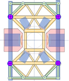
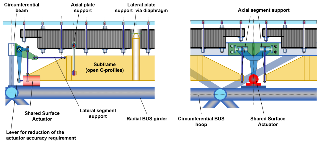
The panel tile array is supported by a dedicated panel segment frame. A typical model of a panel segment frame can be seen in Fig. 9. The panel tiles are mounted and adjusted on a CFRP sandwich baseplate, which is mounted to a steel subframe by four normal (to the mean panel surface) adjuster rods and a thin metal membrane that takes the panel’s in-plane (lateral) loads (e.g. when the reflector is oriented in low elevation angles). The membrane is located in the center of gravity of the set consisting of panel-tiles, panel-tile-adjusters and CFRP sandwich baseplate to avoid the introduction of bending moments by lateral gravity reactions. In this regard, the design principle is similar to a classical optical mirror support. The CFRP baseplate has the function to decouple thermal deformations of the steel backup structure and the steel subframe from the panels.
The panel-segment’s steel subframe is mounted to the main reflector steel backup structure at the panel segment’s corners by a set of four longitudinal actuators in a statically overdetermined way, normal to the mean panel segment surface (one normal translational degree of freedom, two rotational degrees of freedom). Additionally there are three actuators controlling the panel segment’s in-plane translation (two degrees of freedom) and rotation (one degree of freedom). Four panel segments share one actuator for the normal adjustment direction. The intention is to constrain the four panel corners in normal direction to follow the global backup structure deformations (which are then compensated by the actuators in a closed control loop) without generating offsets between the edges of the panel segments. The alternative to this approach is to resort to a static fully determined support of a panel segment in 6 degrees of freedom where edge sensors are required between each set of neighboring panel segments. The latter alternative has the downside of an overwhelmingly large sensor number (for a structure that is constantly fully exposed to the natural environment) and resulting control effort, and is therefore not considered as a baseline solution.
4.3.2 Elevation Rotating Structure
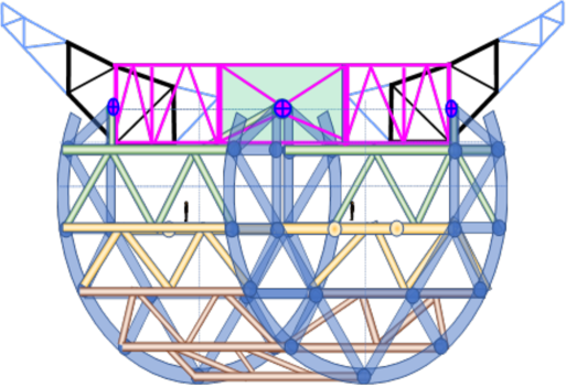
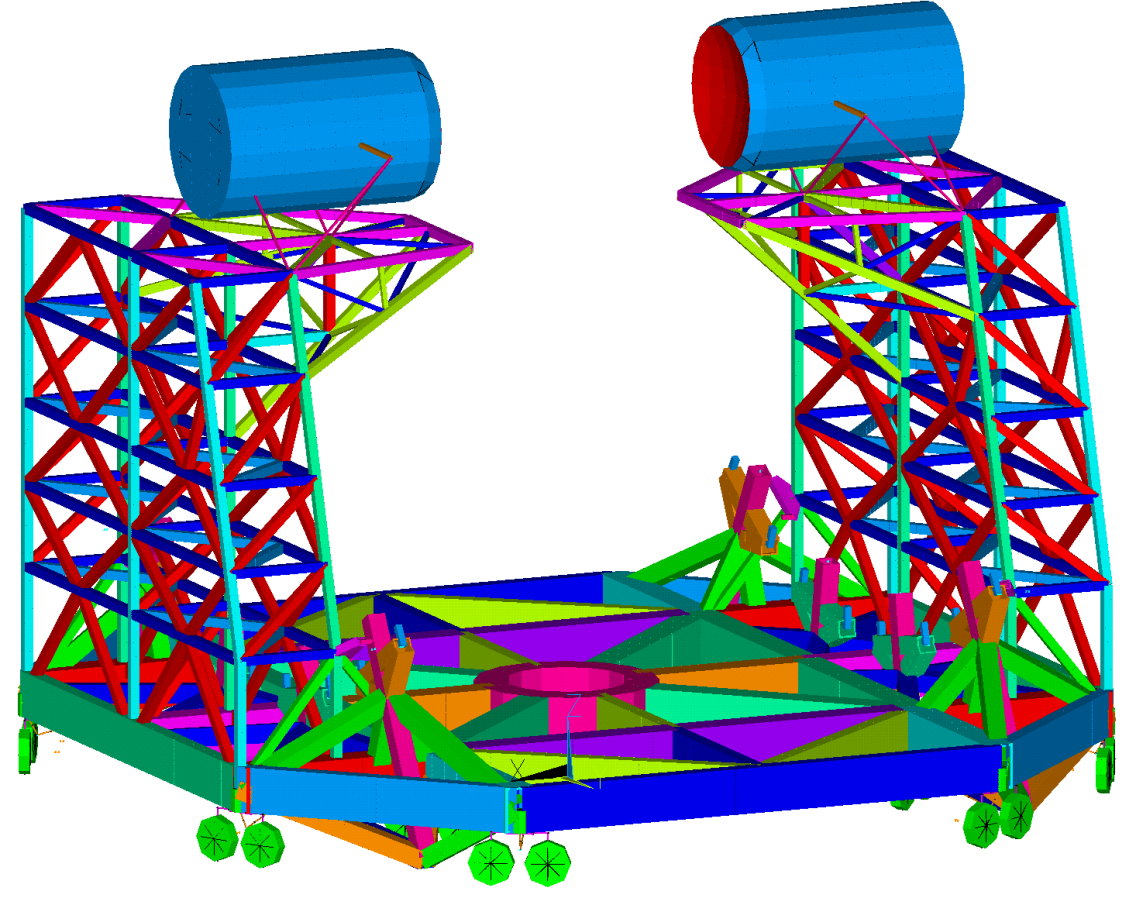
The elevation rotating structure comprises a rocking-chair like structure that provides a large support base for the main reflector and leaves space around the elevation axis to host huge (30 ton; see Table 3) Nasmyth instruments. As an elevation bearing, the rocking chair provides two skids whose tracks are supported by bogies on the azimuth rotating structure which react to radial and lateral forces. The best arrangement of bogies for a robust centering of the elevation axis and the feasibility of a very precise yet robust track that resists high Hertzian stress is still under investigation, the details of which will be reported in Reichert et al. 2024 (in prep). The approach intends to avoid hydraulic bearings due to their maintenance effort and operational costs at the geographic altitude at which the telescope will be constructed. As shown in Fig. 10, the elevation rotating structure consists of all components rotating about the elevation axis. The rocking chair structure to which the elevation tracks are fixed enables rotation about the elevation axis by sitting on bogies.
A cut through the elevation structure is shown in Fig. 10. The elevation rotating structure is currently expected to weigh 2810 tons with some trim mass for later auxiliary components already included. The goal is not to exceed 3000 ton in the course of the ongoing development (see Table 3).
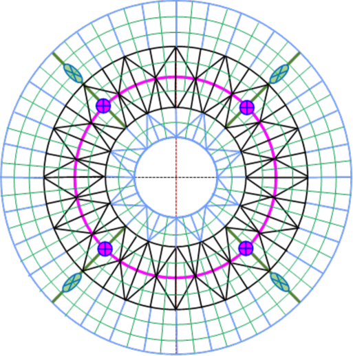
4.3.3 Azimuth Rotating Structure
The azimuth rotating structure is a wheel on track design based on the design concepts used in the 64-m Sardinia Radio Telescope (SRT) and in the 50-m LMT/GTM. It comprises:
-
•
twelve bogies, with two wheels per bogie, riding on on two track rings.
-
•
the azimuth support truss supported by these bogies.
-
•
the elevation bogies (lateral+radial support) carried by the azimuth support truss.
-
•
the Nasmyth instruments racks/towers, also carried by the azimuth support truss.
The azimuth rotating structure can be seen in Fig. 11. The bogies (small green wheels shown in Fig. 11) run on seamless, welded tracks similar to the approach chosen for the LMT/GTM.
One can also see in Fig. 11 the approximate package volumes of the Nasmyth instruments as blue cylinders on top of the racks/towers, and are supported by (motorized, controlled) hexapods, which provide stable support with six degrees of freedom for translational and rotational adjustments.
4.3.4 Eigenfrequencies and mode shapes
The mechanical natural frequencies, or eigenfrequencies, of the structure are an important property as they represent a limitation for the control loop bandwidth of the main axes drives. The controllers’ bandwidths limit their ability to reject environmental disturbances on shorter time scales (higher frequencies) such as wind gusts. The eigenfrequencies are a function of the structure’s ratios of stiffness to mass. For the current design status the first five eigenfrequencies can be seen in Table 4. The first natural mode shape at 1.8 Hz is a twist of the M2 and crown on the quadripod. This mode can be probably improved but is not critical for the main axes control loops. The second and fourth mode shapes are more important for the main axes control loop bandwidth, and show reasonable frequencies given the size and weight of the structure to cope with excitation by wind gusts and earthquakes.
| Mode | [Hz] | Shape Description |
|---|---|---|
| #1 | 1.8 | M2 twist about LOS on quadripod |
| #2 | 1.9 | ERS longitudinal w.r.t. the ARS |
| #3 | 2.1 | ERS lateral w.r.t. the ARS |
| #4 | 3.0 | Full telescope on track rotation about AZ |
| #5 | 3.1 | Lateral bending for Nasmyth instr. |
4.4 Energy Supply and Power Demand
In designing the energy system for AtLAST, determining the future demand of the new 50-m telescope can pose challenges. Both the integration of innovative instrumentation with yet undefined power requirements, and the need to drive such a large (4400 ton; see Table 3) structure faster than similar structures add complexity to the challenge. Presently, we estimate that the power demand, summarized in Table 5, will include 500-700 kW for instrumentation electronics, 480 kW for cryogenic cooling, and an average demand of 500 kW for the telescope drives (namely, the motors), with peak loads for the drives reaching up to 1.7 MW.
| Item | Value | Units |
|---|---|---|
| Instrument Electronics | 600 | kW |
| Cryogenic Demand (on-elevation-axis insts) | kW | |
| Cryogenic Demand (off-elevation-axis insts) | kW | |
| Peak AZ Drive Demand | 1100 | kW |
| Peak EL Drive Demand | 600 | kW |
| Heating, ventilation, & air conditioning | 200 | kW |
| Total Peak Demand | MW |
Recently, we have studied the feasibility of off-grid RES-based energy systems to meet AtLAST’s power needs on the Chajnantor plateau. Hybrid energy systems featuring a large photovoltaic array, lithium-ion batteries, and backup diesel generation were identified as significantly cheaper compared to diesel-only setups (Viole et al., 2023b; Valenzuela-Venegas et al., 2023). Furthermore, hydrogen is gaining traction as an energy carrier in Chile, and is considered a suitable future substitute for backup diesel generation. We have therefore included hydrogen in the proposed energy system.
As noted earlier, the main drives (AZ and EL) are expected to be the main sources of power consumption. Due to the high inertia of the full telescope structure, combined with a high acceleration requirement, considerable power peaks will occur during the acceleration and deceleration phases. During acceleration, the power peak is present as a high power demand with a flow direction from the grid to the drives. On the other hand, during deceleration the drive system generates power, which is typically converted to heat in corresponding brake resistors in most large telescopes.
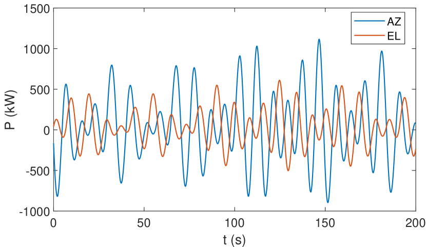
Taking into account the considerable power demand of AtLAST’s main drives, “classic” telescope power management is not acceptable. Assuming the representative example of a Lissajous scan shown in Fig. 2, the expected peak electric power is kW for the AZ-drive and kW for the EL-drive. A time-ordered plot of the power demand is shown in Fig. 12. The major part of this power is due to inertia during acceleration and deceleration, and is thus reusable. For this reason, an energy recuperation system based on supercapacitors is foreseen. The system will shave the electric power peaks and drastically improve the overall efficiency of the telescope’s drive system, which is a major energy consumer; this energy would normally have to be dissipated as heat through braking, but instead can be largely recovered. The full concept will be presented in detail in a separate work (Kiselev et al. in prep).
4.5 Environmental effects
The Atacama Desert is not immune to poor weather or strong seismic events such as earthquakes and volcanic activity. While lightning protection and wind limits (), which necessitate stowing, have already been considered, the team is now working on the detailed modeling of the acceleration during earthquakes. As noted in Otárola et al. (2002), Geo Ambiental Consultores Ltda. (2002), and numerous other ALMA reports, the strength of seismic events is greatly diminished in the Llano de Chajnantor region compared to that at observatories like ESO’s Paranal Observatory, which is closer to the Chilean coast and Chilean fault line. Preliminary results from this work will be reported in Reichert et al. 2024 (in prep), while the modeling will continue into the future as the design approaches full subsystem engineering. In addition, the team plans to perform detailed hydrodynamic simulations to more robustly model the impact of high winds speed and turbulence.
5 Achieving the required surface and pointing accuracy
5.1 General approach
The science cases place very stringent requirements on the antenna design, considering the size of AtLAST and the exposure of its mechanical parts (especially M1 and M2) to the environment. Without compensation, structures of the size and weight of AtLAST will deform on scales that are orders of magnitude larger than the required accuracy of the optical surfaces and optical alignment. Therefore, the structural design of the reflectors and optical path components is an art of maintaining the correct shape of the optical geometry in the presence of deformations due to environmental loads (gravity, wind, thermal loads) as much as possible.
The approach to mitigate the deformations of the AtLAST telescope consists of two main steps:
-
1.
Design and FE analysis of the static structure using structural engineering principles as described in Baars & Kärcher (2018) to achieve a baseline level of performance.
-
2.
Using sensors and actuators in a closed-loop control system to compensate for residual deformation beyond what can be achieved within the static structure. This is expected to bring performance to a much higher level of accuracy. This approach is what is meant here when referring to the “metrology system” in the context of the AtLAST project.
Due to its size, AtLAST is one of the first submm telescopes where active, closed-loop compensation systems are mandatory to fulfill its essential scientific purpose. For example, the primary reflector surface requires an active system to adapt to the gravitational orientation and other environmental loads on seconds time scales. A more detailed overview of the closed-loop compensation concepts considered for AtLAST can be found in Sect. 5.5. A performance analysis using the finite element model described in Sect. 5.3.1 & 5.4 was carried out to verify analytically the performance of the static design as the basis for the closed-loop compensation systems.
5.2 Optical quality metrics
The motivations for the high surface accuracy requirements of AtLAST were discussed in Sect. 2.2.1. Another specific requirement of the AtLAST telescope is its particularly large field of view, in diameter, as discussed in Sect. 2.2.4. The required surface accuracy combined with the wide field imaging capability is a quality metric usually applied to optical telescopes rather than submm telescopes.
To fulfill its scientific requirements, the 2∘ FoV of AtLAST, as mentioned in Sect. 3.2, must be corrected, as the nominal, undisturbed optics alone cannot reach the criterion of being diffraction limited over the full geometric FoV at frequencies GHz (see Mroczkowski et al. 2023 and Gallardo et al. 2024 in prep). We note, however, that the number of beams grows significantly with frequency (), implying that the number of detectors required to fill the usable field of view at higher frequencies will likely remain a goal for the second generation instrumentation. In the first generation, we can anticipate that only the inner portion of the focal surface may be populated with high frequency detectors, while the outer parts could be populated by detectors at GHz, as is done in other mm/submm telescopes.
The Ruze formula (Ruze, 1966), discussed in Sect. 2.2.1 (see Fig. 1), aims to provide an estimate of how surface deformations contribute to the loss in antenna gain. This loss is due to the disturbed propagation of electromagnetic waves through the antenna optics. However, as a metric, Ruze scattering does not account for the full wavefront error for initially undisturbed wavefronts traveling from the aperture stop to specific locations in the focal surface (at the receiver). In addition to the net deformation of the reflecting surfaces themselves, other aspects that affect signal quality include:
-
•
the misalignment of the reflecting surfaces as quasi-rigid bodies relative to each other;
-
•
the specific shape of the instrument geometry and how it matches the focal surface.
These latter two aspects are not covered by classical surface errors evaluated using the Ruze equation. The AtLAST optical design results in a large and curved instrument focal surface. The wavefront error, or proportionally the half wavefront error (HWFE), can be considered as an equivalent metric to the Strehl ratio, discussed in (see Sect. 3.2, Fig. 4). It describes the signal degradation at the focal surface of the instrument, taking into account disturbances that can affect an electromagnetic wave traveling through the entire optical path of the telescope. The wavefront error also allows a spatially resolved assessment of the signal degradation across the curved focal surface. The local RMS surface error of a single reflecting surface is identical to its RMS half wavefront error.
5.3 Optical quality, half wavefront error
As a consequence of the arguments presented in Sect. 5.2, which discussed the requirements and structural design, the half wavefront error was considered as a metric to establish an engineering “error budget.” This error budget is used to set constraints on each subsystem or component by tracking how their tolerance and achievable precision impact the overall result. While the full engineering error budget is beyond the scope of this work, we discuss the salient aspects in the following.
5.3.1 Primary mirror half wavefront error finite element analysis
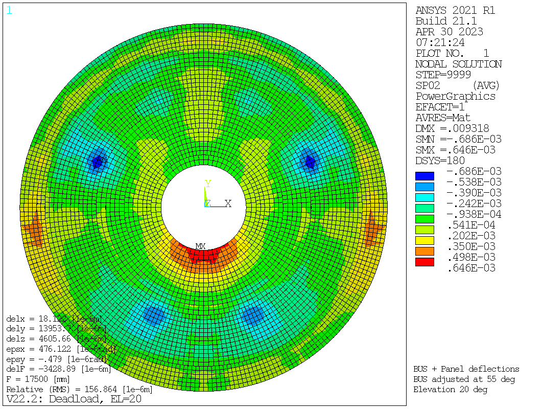
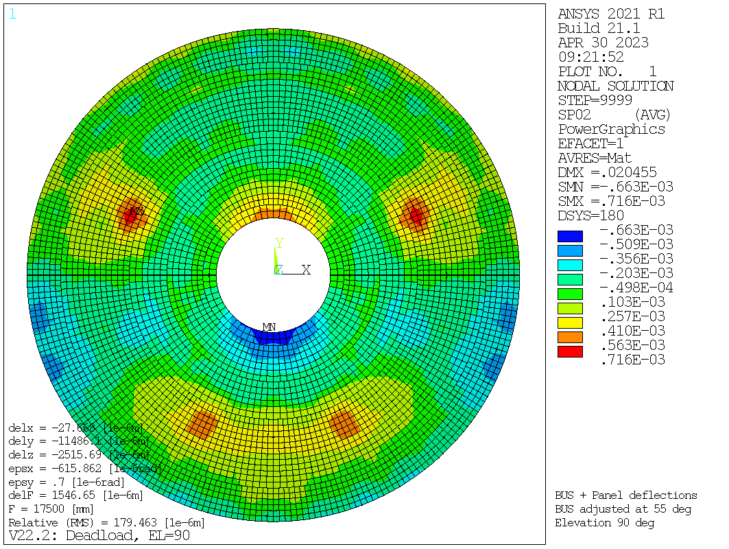
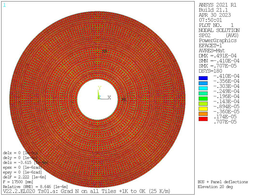
One of the major contributors to the telescope’s half wavefront error budget is the surface deformation introduced by the primary reflector backup structure and the panels. From an engineering point of view, the contribution of the backup structure and the panels can be assessed in separate FE models, since their contribution to the error budget can be expressed as root sum squares. We show the results of the FE modeling of the primary mirror deformations under different conditions in Appendix B. For the results presented in Figs. 24-28, the full panel segment models as shown in Fig. 9 were included in the global telescope model. As a result, the half wavefront errors shown are the root mean squared contributions from the backup structure (whose repeatable contributions can be compensated by the active surface by and large), the global structure and the panel segments. Figs. 24 & 25 show the mostly repeatable contribution of the gravity deformations at the extreme limits in elevation (namely, and ), where the fractional error contributed by the backup structure can be compensated by the active surface. Fig. 26 shows the HWFE caused by a quasi-static wind load for a wind speed of at and for the worst case, wind from the front (which means the azimuth angle of attack is ). Fig. 27 shows the HWFE for a temperature deformation mode that can be compensated by an active primary reflector surface. Fig. 28 shows a temperature gradient normal to the surface within the panel tiles that cannot be compensated by any control system considered so far. It should be noted, however, that the magnitude of the temperature gradient is a deliberately chosen assumption, and its real magnitude will have to be verified in future analysis or prototype measurements.
5.4 Pointing accuracy
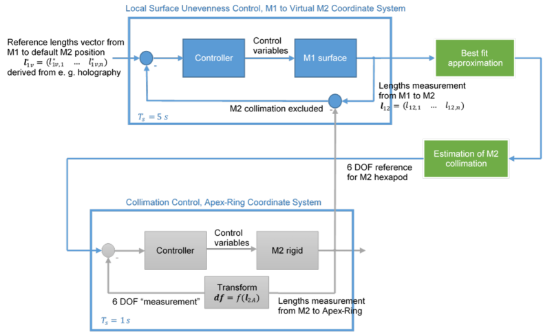
The pointing accuracy needs to considered in conjunction with the closed-loop control system for the active surface and the optical alignment, described in 5.6. The pointing will be the secondary property to be controlled after the primary control of the M1 surface and the alignment of the optical components to ensure the required half wavefront error. This alignment, when considered as rigid bodies, can be described by three translations and three rotations, which are coupled to the pointing direction by a sensitivity matrix. The remaining pointing errors contributors will be addressed by the measures described in the following passage. To achieve our pointing accuracy requirement, we plan to implement a static pointing error correction model (SPEM) combined with closed-loop control compensation techniques, such as the so-called flexible body compensation (FBC) approach (Kärcher, 1999, 2006; Baars & Kärcher, 2018). Additionally, a new approach using machine learning algorithms that can include sensor data and more factors must be developed. A description of such a new approach is given in Nyheim et al. (2024).
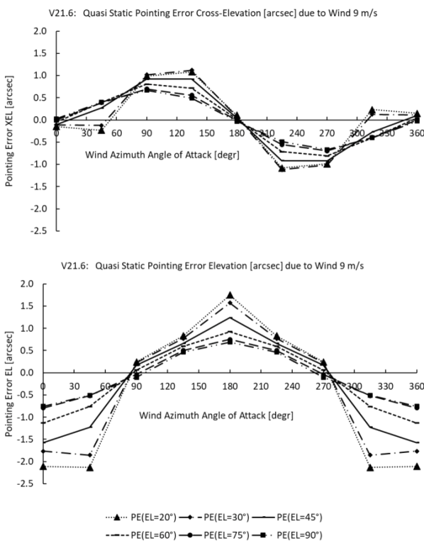
The most critical and difficult pointing errors for which to compensate are likely to come from wind loads. The wind loads can be divided into stationary and dynamic loads relative to the antenna structure by the eigenfrequencies of the principal axis control loops, which are limited by the first eigenfrequencies of the structure. Fig. 13 shows the residual pointing error due to stationary wind loads (assuming that the measured values of the principal axis angle sensors are already compensated to zero). The diagram shows elevation and cross-elevation pointing errors separately (cross-elevation is the axis of rotation perpendicular to the elevation axis, the position of which is defined by the current elevation angle). The abscissa shows the wind azimuth angle of attack. The ordinate indicates the directional error in arc seconds. Each line represents the pointing error for a specific elevation angle of the telescope.
5.5 Metrology concepts
AtLAST surface accuracy requirements (nighttime value of 20 m RMS, as in Table 6) are more demanding than any mm/submm large single dish has achieved, and—unlike smaller aperture submm telescopes—will require an active surface coupled with a metrology system to measure it continuously. A number of large single dish telescopes with active surfaces, such as the 100-meter GBT, have met or even exceeded their original surface accuracy requirements by relying on out-of-focus (or phase retrieval) holography using bright, compact astronomical sources, and have achieved good results (Hunter et al., 2011; Mason, 2014; White et al., 2022). However, astro-holographic approaches also incur large observing overheads and can lead to unknown calibration systematics as the beam quality degrades between focusing procedures. Recently, many of the large single dish telescopes operating at mm-wavelengths have begun to upgrade their systems to implement metrology. This provides a valuable pathfinder, and AtLAST plans from the beginning to include in its design the ability to have closed-loop metrology continuously updating the focusing solutions within seconds.
To our knowledge, there are three main approaches151515Additionally, live photogrammetry, updating on timescales of a few seconds, can be expected to achieve 150-500 m accuracy depending on the configuration of targets on M1 and the angles covered by the cameras (see Buffa et al., 2016, for simulations of different configurations on the 64-m SRT). now being developed into potentially viable metrology systems: those based on direct measurements using lasers to scan the surface (e.g. Salas et al., 2020), those based on millimetric wavefront sensing (e.g. Naylor et al., 2014; Tamura et al., 2020), and those using laser interferometry to track changes in the path length (Rakich et al., 2016; Attoli et al., 2023). The first was being developed on the 100-m Green Bank Telescope as the Laser Antenna Surface Scanning Instrument (LASSI), but appears to be limited by the scanning strategy to slower than real time performance and will require further technical development before a full demonstration (private communications). The second technology, has now been tested as a two-element prototype on the Nobeyama 45-meter telescope (Nakano et al., 2022), and has demonstrated a precision of m, though further work will be required to fully implement it and show how it scales. The third technology, being developed for the Giant Magellan Telescope (GMT) and the 64-m SRT, relies on the Etalon Absolute Multiline Technology161616See https://www.etalonproducts.com/en/products/absolute-multiline-technology/. to achieve, in principle, a precision of m, exceeding the requirement that the measurement system deliver better precision than the surface accuracy requirement in order to implement real time corrections.
We note that the approaches considered here are broadly and more properly “active optics,” which correct the telescope focus and relative alignment of the optical components, but do not account or attempt to correct for the atmospheric phase variations in the way adaptive optics used on visible band optical telescopes can by using an artificial guide star to track atmospheric seeing. A by-product of the live metrology will be lower beam uncertainty and better calibration accuracy. Calibration systematics have been one of the primary limitations or uncertainties in many mm-wave surveys, presenting few percent level systematics that affect constraints from CMB analyses (Hasselfield et al., 2013; Lungu et al., 2022).
5.6 Closed-loop approaches for optical quality and pointing corrections
The metrology approach (meaning, in this context, the sensors, controllers, and actuators in a closed loop) for the AtLAST telescope aims to address two performance domains which are physically coupled by separated correction loops:
-
•
Control loop for the optical quality for maintaining the surfaces accuracy (across the primary reflector) and keeping the optical elements aligned as rigid bodies in six degrees of freedom per element. It must be noted that the latter alignment couples with the pointing direction.
-
•
Pointing correction loop to correct pointing direction of the overall optical assembly while using solely the main axes drives for corrections. Temperature and distance measurement sensors in the major support structure are planned to be used.
The control system can be considered as a cascaded design. The primary, inner, control loop is the one that keeps the optical elements aligned and the surfaces as nominal as possible. The secondary, outer control loop corrects the residual pointing error and the fraction that is contributed by observable, but non-repeatable deformations of the structure, as far as possible.
5.6.1 Closed-loop active surface and optical alignment approach
The system that ensures the optical quality by maintaining the primary reflector surface accuracy and keeping the optical elements aligned can be divided in the following groups:
-
1.
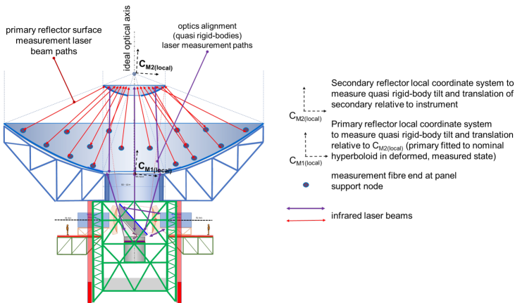
Sensors detecting deformations of the primary reflector surface relative to the secondary reflector, where the secondary reflector is considered as a virtual rigid body (e.g. by fitting its deformation to its nominal shape). The choice of a sensor system that achieves the required accuracy over the large, absolute dimensions of the primary reflector while being exposed to the environment is a major challenge. The only sensor system showing both the required accuracy and the best technology readiness level (TRL)171717See https://horizoneuropencpportal.eu/store/trl-assessment for definitions of TRL. so far was the Etalon Absolute Multiline Technology. Its TRL is estimated to be 5-6, and thus will require further development and testing before being considered ready for AtLAST.
-
2.
Sensors detecting alignment changes between the optical elements. Here the same technology as for the primary reflector surface can be used. The Etalon Absolute Multiline Technology is already used for this purpose in optical telescopes such as ESO’s Very Large Telescope (VLT), the Large Binocular Telescope (LBT) and the future Giant Magellan Telescope (GMT; Rakich et al., 2016).181818See also https://www.etalonproducts.com/en/absolute-multiline-technology-for-the-giant-magelan-telescope/. The arrangement of the sensors (surface and alignment) can be seen in Fig. 14.
-
3.
Linear Actuators for the alignment of the primary reflector panel segments. It can be expected that not all panel segment corners need to be supported by actuators since the deformation patterns to be corrected originate from the backup structure, and are of large scale, corresponding to or including mainly low order Zernike terms. A scheme for how the linear actuators can be arranged at the corners of a panel segment frame is shown in Fig. 15.
-
4.
Actuators controlling six (or fewer if not required) rigid body degrees of freedom of the optical elements (except for the primary reflector). The secondary reflector and the instrument are intended to be adjustable by six linear actuators comparable to a Stewart platform, but with a different geometrical arrangement of the actuators.
-
5.
The control system driving the corrections as a cascaded loop which is shown as a sketch in Fig. 16.
5.7 Panel surfacing and solar scattering
The main challenge to performing Solar observations with a submm telescope is to reduce the loading power from the Sun that, if focused onto the receiver or any other component, would likely be dangerous and would at minimum jeopardize equipment, while still retaining the ability to carry out the submm observations. Due to this challenge and the associated risks, most millimeter and submillimeter telescopes cannot observe the Sun; ALMA is a notable exception and can provide an example for AtLAST in this regard.
In fact, the ALMA observatory features several different antenna designs, providing three demonstrated approaches for implementing surface treatments that would enable direct observations of the Sun. All of these approaches rely on some form of scattering of the infrared and optical radiation by adding features that are sub-wavelength sub-terahertz frequencies, and with surface roughnesses well below the 20 m half wavefront error demanded by AtLAST’s science requirements (Table 6).
In short, the approaches in use by ALMA are 1) sandblasting of the mandrell used to electro-form the nickel subreflector panels, which are then plated in aluminum to avoid corrosion, 2) chemical etching of aluminum subreflector panels, or 3) scalloping of the subreflector surfaces during their manufacture by milling (direct machining). Control of the feature size and shape in the third case is achieved through the choice of tool size and milling feed rate parameters.
ALMA Memo #329 (Lamb, 2000), which supersedes ALMA Memo #266 (Lamb, 1999), shows that the efficiency that the panel reflects solar radiation at frequencies well above AtLAST’s range of interest can be reduced to only through the use of simple triangular grooves. Later, Schwab & Cheng (2008) showed that a more random, chemically-etched surface will have a specular reflection , roughly three times lower.
We further note an advantage AtLAST has in this regard, due to its 12-meter large secondary mirror (M2). While the collecting area of AtLAST M1 is larger than that of an ALMA antenna, the ratio of the areas of the primary to the secondary reflectors is much smaller for AtLAST than for ALMA, meaning the energy reflected by AtLAST M1 will be distributed over a greater area. Concretely, that ratio is for AtLAST, and for an ALMA 12-m element, which features a 0.75 meter diameter secondary mirror. Considering the intrinsic concentration of scattered light at the AtLAST secondary will be lower than it is for ALMA, this will further reduce the heat loading and therefore reduce the challenges associated with implementing Solar observing modes.
6 Instrumentation Considerations
AtLAST is designed to be a facility telescope serving a broad range of scientific goals. Following the recommendations of the instrumentation community and of the operations study, we have designed the telescope to facilitate the large number of science goals described in Ramasawmy et al. (2022), Booth et al. (in prep), and the AtLAST science cases (Cordiner et al., 2024 in prep; Di Mascolo et al., 2024 in prep; Klaassen et al., 2024 in prep; Lee et al., 2024 in prep; Liu et al., 2024 in prep; Orlowski-Scherer et al., 2024 in prep; van Kampen et al., 2024 in prep; Wedemeyer et al., 2024 in prep). The design allows up to six nominal dedicated instrument positions, selected only by an axial rotation of the tertiary mirror. As discussed in Groppi et al. (2019), van Kampen (2022), and Kohno et al. (2020), the types of instrumentation are expected to fall into one of the four following broad categories:
- •
- •
- •
-
•
Multi-band single-beam heterodyne receivers that would allow AtLAST to participate in very long baseline interferometry (VLBI) or, potentially, the Next-Generation Event Horizon Telescope (ngEHT) observational campaigns (Johnson et al., 2023).
Of these, the power and cryogenic cooling requirements will likely be driven by the first, which are the most massive.
6.1 Instrument sizes and cooling requirements
It is difficult to convey intuitively just how large each of these instruments can ultimately be in comparison to current facility instruments. The four smaller Cassegrain-mounted, or off-elevation-axis, instruments, with diameters of meters (about the width of a standard shipping container). These are specified to be up to 10 tons each, and will be secured to the top of the elevation wheel structure as they are co-moving in elevation (see the red instruments in Fig. 17). They are expected to be comparable in diameter (and focal ratio, as discussed in Sect. 3), to the receiver designs for SO (Zhu et al., 2021; Bhandarkar et al., 2022), CCAT (Vavagiakis et al., 2018), and CMB-S4 (Gallardo et al., 2022). Based on this experience, the power requirements for the cryogenic cooling systems for the off-elevation-axis instruments are estimated to be kW per receiver (Table 5). For example, Zhu et al. (2021) noted that the SO Large Aperture Telescope Receiver (LATR) uses two Cryomech PT90191919See https://bluefors.com/products/pulse-tube-cryocoolers/pt90/. and two Cryomech PT420202020See https://bluefors.com/products/pulse-tube-cryocoolers/pt420/. pulse tubes, which total kW. While tilting and tipping of the off-elevation-axis instruments could present an engineering challenge for the cryogenics, a number of instruments have been operating while tipping over a greater range of angles for over a decade (e.g. Dicker et al., 2008; Tan, 2008; Dicker et al., 2014). Further, dedicated tests (Tsan et al., 2021) have shown that the impacts of tipping a cryogenic pulse tube typically used for sub-4 K receivers as much as are minimal. We also note that the heterodyne receivers in ALMA are co-moving in elevation and have been operating for over a decade.
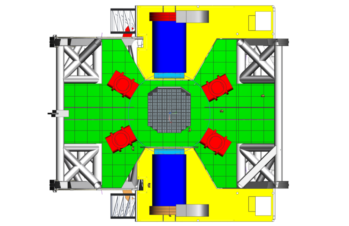
The two larger instruments, meanwhile, are larger as the are intended to take advantage of the full 4.7-meter focal surface of AtLAST, corresponding to the full 2∘ diameter geometric FoV. We chose to design the mount points for these to be Nasmyth (i.e. fixed in elevation while the telescope points; see the blue instruments in Fig. 17). This is due to their exceptional volumes and masses (up to 30 tons, see Table 3), the desire to facilitate operations, installation, access to the large instruments, cabling, and electronics for maintenance, and to accommodate the likely scenario they will be modular. We refer to these as ‘on-elevation-axis’ since they are co-axial with the elevation axis. As the focal surface areas of the on-elevation-axis instruments are four times larger than those of the smaller instruments, we estimate the cooling requirements to be four times larger as well, resulting in a power budget of 160 kW per instrument for the cryogenics alone (Table 5).
All six instruments are allocated a length of up to 6 meters, about the length of a typical shipping container used for freight, which will allow for readout and back-end electronics to be directly mounted on the backs of the instruments or the floor nearby.
We note that the Nasmyth support platforms put the weight of the instruments directly on the azimuthal support structure, rather than the primary mirror backup structure. This places an additional demand on the antenna stiffness as the on-elevation-axis instruments are no longer directly attached to the same support structure that carries the telescope optics (i.e. M1, M2, and M3). Finite element analysis shows that the relative pointing offset between the optical field of view and the instrument is acceptable, with the worst offsets during azimuthal turnaround (see Table 4, modes #2 and #4).
6.2 Receiver cabin and instrument installation
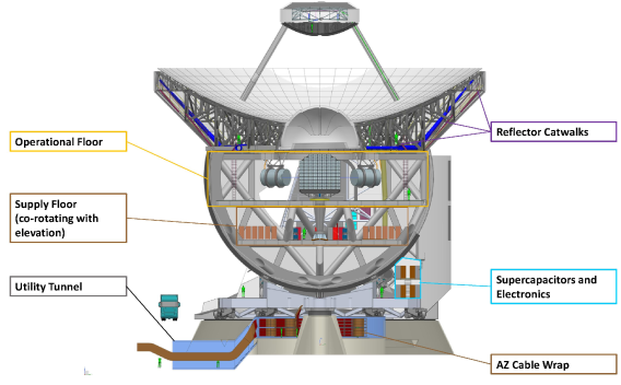
A cutaway view of the AtLAST CAD model is shown in Fig. 18, revealing the telescope interior. At the top, a catwalk structure allows access to the backs of the main reflectors’ panels, the backup structure’s heating, ventilation, and air conditioning (HVAC) system (blue), and the tile segment actuators. A yellow box in the same figure shows the main floor of the receiver cabin, where the science instruments themselves are located. Along with the instrument position within the telescope comes the task to install the six instruments into their operational position. This is essential during commissioning, and is also expected be required occasionally during the lifetime of the instrument (e.g. for maintenance and upgrades). Taking the foundation of the AZ-track as the zero-level, the instrument must be lifted by 18.6 m to reach the operational floor.
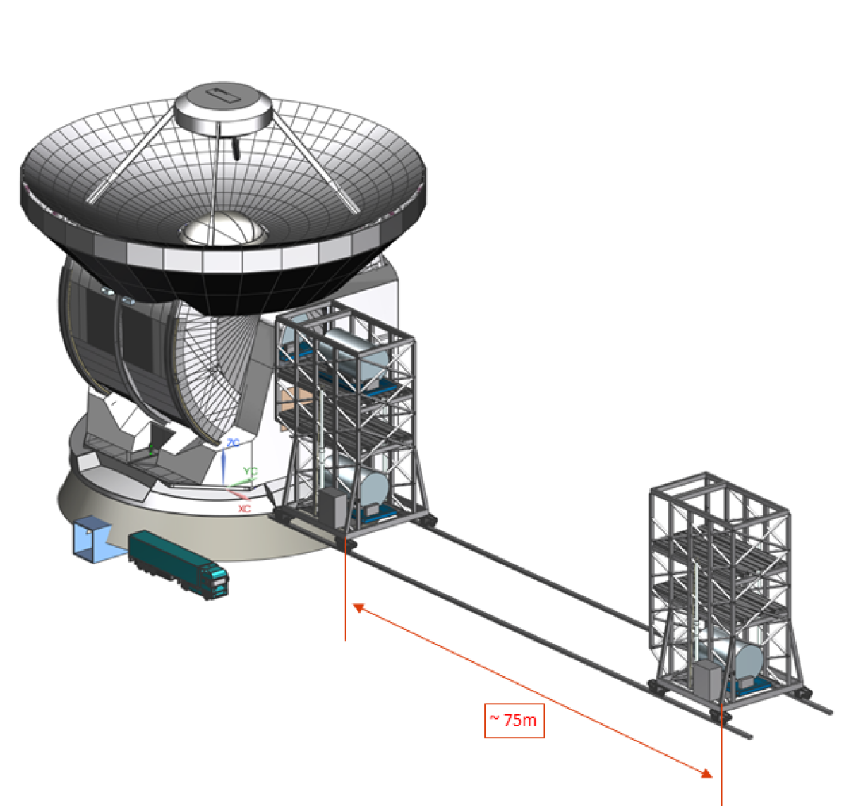
We identified a system completely separate from the telescope structure to fit best AtLAST’s requirements (shown in Fig. 19). A stand-alone system can access all four sides of the telescope, so that all instruments (and as necessary other devices) can be lifted with the same shared device and the transport systems in the telescope can be reduced to a minimum. As a result, it removes weight from the telescope structure and thus reduces the main axis moments of inertia and system complexity. As an additional benefit, this lifting device is also to be equipped so that it can be used for M2 maintenance activities. Since such a separate system would interfere with the beam, it must either be foldable or be able to be removed from the vicinity of the telescope. It was determined that the minimum distance must be at least 75 m to be clear of the beam when the telescope is pointing at its lower elevation limit. The rail mounted system shown in Fig. 19 was designed by taking into account the prospective AtLAST sites,212121See “Measuring the wind at 5000 m above sea level” (2023). both of which are rather flat. For transportation, the instruments should be mounted on special, actively driven racks (Fig. 19, blue platform below the science instrument), which can also remain on the instruments for transportation to the final maintenance building using a customized trailer. In addition to this instrument lifting device, there are two standard passenger elevators located at each Nasmyth tower for transportation of personnel and small equipment.
Below the receiver cabin in Fig. 18, the brown boxed region shows the space dedicated for support electronics, computing/data storage, and cooling equipment (e.g. compressors) for the off-elevation-axis instruments and the active M1 surface system. The light blue region shows the space on the azimuth disk hosting the supercapacitors to be used in the regenerative braking/power recuperation system and the main axis control systems (see Sect. 4.4).
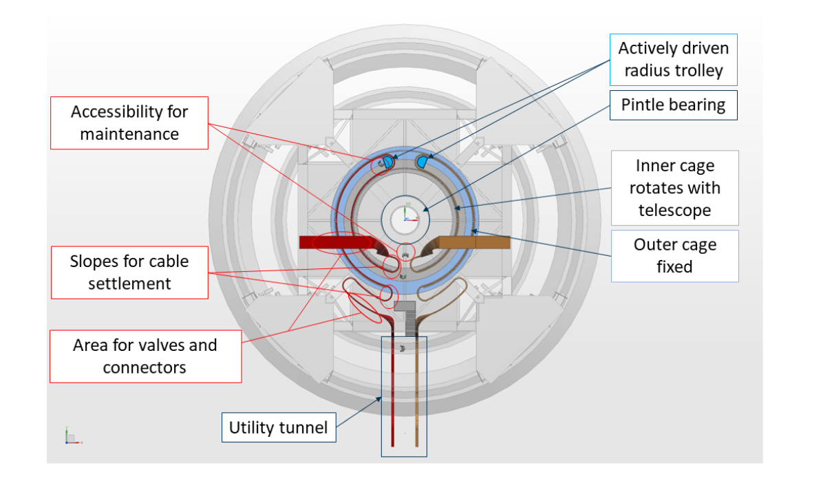
To supply all these systems with sufficient electrical power, helium, data network, chilled water and compressed air most of the area within the foundation—below the azimuth wheel on track system—is reserved for the azimuth cable wrap. Fig. 20 presents the minimum sizes needed for cable wrap in terms of bending radii and maintenance areas. According to the telescope movement the azimuth cable wrap will have a turning range of 540∘ and must be able to deal with the telescope’s maximum turning speed of 3 and max. acceleration of 1. Multiple drives and brakes are installed that pull robotic energy chains synchronized to the telescope movement. To guide the chains and for protection of staff, the AtLAST cable wrap should have an inner and outer guide channel, with the inner one rotating with the telescope and cable wrap drives. The outer guide channel shall be fixed to the foundation and has a diameter of 14.5 meters. The most challenging design drivers are the size, maintenance requirements (accessibility) and the bearing design of the cable wrap. The AZ cable wrap is served by a utility tunnel that runs beneath the telescope’s azimuth rails (see Fig. 18 for comparison).
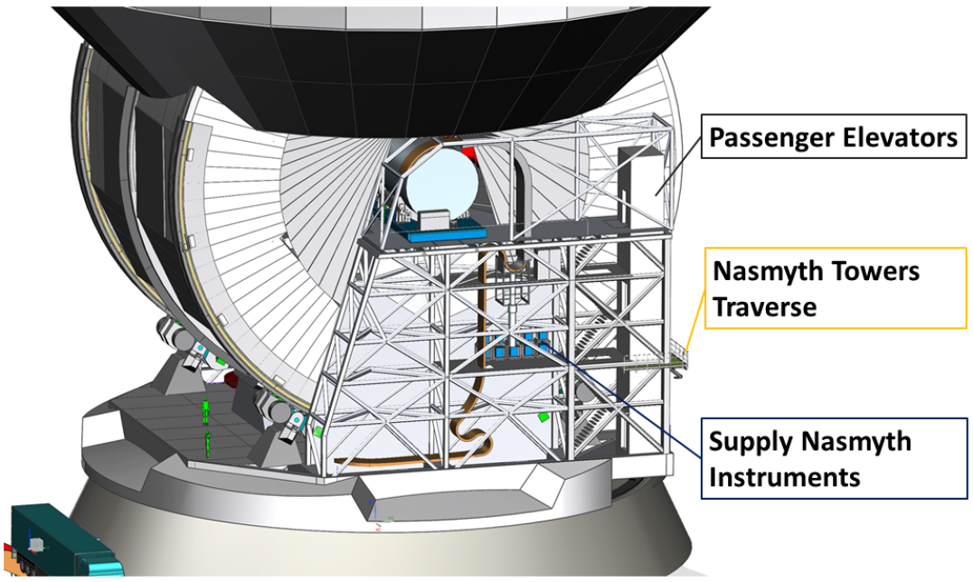
For systems that are co-rotating in elevation and that need to be supplied, for instance, the off-elevation-axis instruments or the active M1 surface, the elevation cable wraps are located in each Nasmyth tower, visible in Fig. 21. This guarantees excellent accessibility for maintenance. The EL-cable wraps require a turning range of 76∘ (to allow margin for safety beyond the nominal elevation range), a maximum speed of 3, and a maximum acceleration of 1. They are also actively driven by linear actuators. The on-elevation-axis instruments can be supplied and supported separately with equipment hosted in the areas within the Nasmyth towers (see Fig. 21).
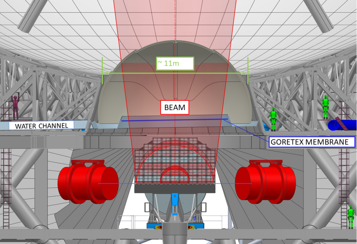
Fig. 22 shows the planned concept for protecting the receiver cabin from the elements (e.g. rain, snow, wind, and dust). Along with the optical layout described in Sect. 3 comes the fact that the M1 reflector has an opening of 11 meters in its middle. Given the environment in which AtLAST will be situated, it was decided to have two complementary systems for protecting the receiver cabin from the outside elements. As a baseline, the function to protect the interior during operation is to be executed by a Goretex® membrane that is considered acceptable for submillimeter wavelengths (e.g. Koller et al., 2000), and has been demonstrated at larger sizes by the JCMT, where the screen shields the entire 15-meter telescope (e.g Hills, 1990). We note, however, that there is evidence that GoreTex® may not be ideal in terms of high frequency transmission and polarization properties (Greaves et al., 2003; Mairs et al., 2021), and further investigation into alternative materials is needed.
During the non-operating period and for extreme weather conditions a second, more robust system is foreseen. With regard to the areas required for the main reflector backup structure and the beam, we find that a spherical shape is best suited to AtLAST’s conditions. Both a fiberglass shell widely used for small telescopes or a tent shell as planned should meet AtLAST’s requirements, with a fiberglass shell as baseline design (as used by, e.g., the European Solar Telescope; see Hammerschlag et al., 2010). The shell of this shutter also provides water management to channel rainwater and snow from M1 away from the telescope interior. The inside of the M1 backup structure will be sealed in the plane of the carbon fiber reinforced plastics sandwich baseplates of the structure (see Fig. 9). The shutter guides the water to outlets on the side of the telescope.
6.3 Wobbler/nutator considerations
Many single-beam instruments on smaller facilities have benefited from the ability to rapidly switch between an on-source and off-source position. Typically this is achieved through a chopper or nutating secondary mirror, which “throws” the beam a few arcseconds off-source for approximately half the integration time. For a single beam in the ideal case, the instrument is modulated in a square wave, and the modulation occurs at a rate faster than the atmosphere evolves. Since 50% of the time is spent on source, and 50% is on a background sky position that is assumed to be free of significant astronomical signals, there is a noise penalty for both. First, the signal is only measured half the time, and second the measurement of the off-position is just as noisy, so the effective on-source integration time is comparable to 25% of the total.222222Given the advances in focal plane array technology, and the fast scanning capabilities of the AtLAST design, a small focal plane array with a sufficient number of elements may obviate the need for a wobbler in most cases, getting around the on/off-source noise penalty by keeping a number of beams on source at all times, while the rest of the beams sample the background sky signal. Proper forecasting in upcoming works will explore this.
The secondary and tertiary mirrors of AtLAST are too large to serve as nutators, and making them smaller would sacrifice the field of view. Detecting broad and faint spectral lines, such as those expected in emission from massive galactic-scale molecular outflows (Cicone et al., 2014, 2018) and from the circumgalactic medium (CGM) of galaxies (Lee et al., 2024 in prep; Cicone et al., 2021), require stable spectral baselines. For these kinds of science cases, it may be worth to sacrifice a portion of the FoV to apply the wobbler concept developed by R. Hills and presented in AtLAST Memo #2 (Hills, 2022). This memo provides a contingency plan that avoids modulating either the massive secondary or tertiary mirror. This wobbler concept, inspired by his work on the JCMT, relies on Crossed-Dragone relay optics to reimage and allow the installation of a small wobbler at the pupil. One of the advantages of this concept over traditional approaches is that this wobbler is in principle optically perfect: since it modulates at the pupil, it is modulating an exact optical image of the primary mirror. Further, the optics could be housed in the receiver, meaning they 1) do not interfere mechanically or require modification to the antenna optics, and it would allow them to be cooled to cryogenic temperatures, which would minimize any additional loading (noise).
7 Conclusions
The next decade of developments is poised to revolutionize submillimeter astronomy, with AtLAST potentially becoming the flagship in this effort. In this work, we have presented the conceptual design for AtLAST, and the results of finite element modeling for the structural deformations due to wind, gravity, and thermal effects. Most importantly, we find that the demanding science requirements drive us to an innovative design quite unlike any existing millimeter or submillimeter facility. Further work will provide more complete details on the antenna structural design (Reichert et al. 2024 in prep), the optical design and corrections (Gallardo et al. 2024 in prep), the effects of panel gaps and scattering on the beam (Puddu et al. 2024 in prep), and a novel kinetic energy recuperation system (Kiselev et al. 2024 in prep).
The design presented here is expected to meet the all of the specifications set for AtLAST to achieve its broad scientific goals. In this work, we have identified and discussed in depth the key technical requirements needed to achieve these science goals, which in turn drive the most stringent aspects of the design. Namely, these are: the large field of view, the high surface accuracy, fast scanning and acceleration, and the need to deliver a sustainable, upgradeable facility that will serve a new generation of astronomers and remain relevant for the next several decades.
At the same time, while we have gained sufficient confidence in the feasibility of the conceptual design, a few key aspects of the design have been identified for further testing, prototyping, and demonstration before construction can begin. These include a field demonstration of the closed-loop metrology to keep the overall optical surface accurate to better than 20 m half wavefront error, field demonstrations of the power generation and energy recuperation concepts, computational fluid dynamics simulations to fully assess the impact of wind and turbulence on the pointing and focus, and a seismic hazard analysis to deliver detailed loads and design criteria for the particular sites of interest. Despite the amount of work that remains to be done, AtLAST is on track to potentially begin construction, if fully funded, later this decade.
Acknowledgements.
This project has received funding from the European Union’s Horizon 2020 research and innovation program under grant agreement No. 951815 (AtLAST).232323See https://cordis.europa.eu/project/id/951815. We are grateful for the guidance and inspiration from Richard Hills throughout the early phases of the telescope design.References
- Attoli et al. (2023) Attoli, A., Poppi, S., Buffa, F., et al. 2023, in 2023 XXXVth General Assembly and Scientific Symposium of the International Union of Radio Science (URSI GASS, 135
- Baars et al. (1987) Baars, J. W. M., Hooghoudt, B. G., Mezger, P. G., & de Jonge, M. J. 1987, A&A, 175, 319
- Baars & Kärcher (2018) Baars, J. W. M. & Kärcher, H. J. 2018, Radio Telescope Reflectors: Historical Development of Design and Construction, Vol. 447
- Bangert & Meyer (1997) Bangert, M. L. & Meyer, W. M. 1997, Cosmic Origins Spectrograph (COS). Volume I, Science investigation and technical proposal P97-752, Cosmic Origins Spectrograph (COS). Volume I, Science investigation and technical proposal P97-752 : April 15, 1997, prepared for Goddard Space Flight Center, National Aeronautics and Space Administration, Greenbelt, MD 20771-0001 / [Merv L. Bangert, Wallace M. Meyer]. [Boulder, Colo. : Ball Aerospace & Technologies Corp.] ; 1997. QB500.268 .C6 1997
- Bhandarkar et al. (2022) Bhandarkar, T., Bhimani, S., Coppi, G., et al. 2022, in Society of Photo-Optical Instrumentation Engineers (SPIE) Conference Series, Vol. 12190, Millimeter, Submillimeter, and Far-Infrared Detectors and Instrumentation for Astronomy XI, ed. J. Zmuidzinas & J.-R. Gao, 1219012
- Bongards (1923) Bongards, H. 1923, ApJ, 58, 307
- Booth et al. (1987) Booth, R. S., de Jonge, M. J., & Shaver, P. A. 1987, The Messenger, 48, 2
- Booth et al. (1989) Booth, R. S., Delgado, G., Hagstrom, M., et al. 1989, A&A, 216, 315
- Buffa et al. (2016) Buffa, F., Pinna, A., & Sanna, G. 2016, ISPRS Annals of Photogrammetry, Remote Sensing and Spatial Information Sciences, III5, 113
- Carpenter et al. (2023) Carpenter, J., Brogan, C., Iono, D., & Mroczkowski, T. 2023, in Physics and Chemistry of Star Formation: The Dynamical ISM Across Time and Spatial Scales, 304
- Carpenter et al. (2019) Carpenter, J., Iono, D., Testi, L., et al. 2019, ALMA Memo 612, https://library.nrao.edu/public/memos/alma/main/memo612.pdf
- Cicone et al. (2021) Cicone, C., Mainieri, V., Circosta, C., et al. 2021, A&A, 654, L8
- Cicone et al. (2014) Cicone, C., Maiolino, R., Sturm, E., et al. 2014, A&A, 562, A21
- Cicone et al. (2018) Cicone, C., Severgnini, P., Papadopoulos, P. P., et al. 2018, ApJ, 863, 143
- Cordes (2008) Cordes, J. M. 2008, in Astronomical Society of the Pacific Conference Series, Vol. 395, Frontiers of Astrophysics: A Celebration of NRAO’s 50th Anniversary, ed. A. H. Bridle, J. J. Condon, & G. C. Hunt, 225
- Cordiner et al. (2024 in prep) Cordiner, M. et al. 2024 in prep, …, in prep.
- Cortés et al. (2020) Cortés, F., Cortés, K., Reeves, R., Bustos, R., & Radford, S. 2020, A&A, 640, A126
- Delsemme & de Duve (1998) Delsemme, A. H. & de Duve, F. b. C. 1998, Our cosmic origins : from the Big Bang to the emergence of life and intelligence
- Di Mascolo et al. (2024 in prep) Di Mascolo, L. et al. 2024 in prep, …, in prep.
- Dicker et al. (2014) Dicker, S. R., Ade, P. A. R., Aguirre, J., et al. 2014, in Society of Photo-Optical Instrumentation Engineers (SPIE) Conference Series, Vol. 9153, Millimeter, Submillimeter, and Far-Infrared Detectors and Instrumentation for Astronomy VII, ed. W. S. Holland & J. Zmuidzinas, 91530J
- Dicker et al. (2018) Dicker, S. R., Gallardo, P. A., Gudmundsson, J. E., et al. 2018, in Society of Photo-Optical Instrumentation Engineers (SPIE) Conference Series, Vol. 10700, Ground-based and Airborne Telescopes VII, ed. H. K. Marshall & J. Spyromilio, 107003E
- Dicker et al. (2008) Dicker, S. R., Korngut, P. M., Mason, B. S., et al. 2008, in Society of Photo-Optical Instrumentation Engineers (SPIE) Conference Series, Vol. 7020, Millimeter and Submillimeter Detectors and Instrumentation for Astronomy IV, ed. W. D. Duncan, W. S. Holland, S. Withington, & J. Zmuidzinas, 702005
- Fluxa Rojas et al. (2016) Fluxa Rojas, P. A., Dünner, R., Maurin, L., et al. 2016, in Society of Photo-Optical Instrumentation Engineers (SPIE) Conference Series, Vol. 9914, Millimeter, Submillimeter, and Far-Infrared Detectors and Instrumentation for Astronomy VIII, ed. W. S. Holland & J. Zmuidzinas, 99142Q
- Frayer (2017) Frayer, D. T. 2017, arXiv e-prints, arXiv:1706.02726
- Gallardo et al. (2022) Gallardo, P. A., Benson, B., Carlstrom, J., et al. 2022, in Society of Photo-Optical Instrumentation Engineers (SPIE) Conference Series, Vol. 12190, Millimeter, Submillimeter, and Far-Infrared Detectors and Instrumentation for Astronomy XI, ed. J. Zmuidzinas & J.-R. Gao, 121900C
- Gallardo et al. (2024) Gallardo, P. A., Puddu, R., Harrington, K., et al. 2024, Appl. Opt., 63, 310
- Geo Ambiental Consultores Ltda. (2002) Geo Ambiental Consultores Ltda. 2002, ALMA Memo Series, 418, https://library.nrao.edu/public/memos/alma/main/memo418.pdf
- Giovanelli et al. (2006) Giovanelli, R., Sebring, T., Radford, S., et al. 2006, Cornell Caltech Atacama Telescope: Feasibility/Concept Design Study Final Report, Cornell Caltech Atacama Telescope: Feasibility/Concept Design Study Final Report, January 2006
- Gómez Toribio et al. (2021) Gómez Toribio, P., Mroczkowski, T., Cabré, A., et al. 2021, arXiv e-prints, arXiv:2103.03917
- Greaves et al. (2003) Greaves, J. S., Holland, W. S., Jenness, T., et al. 2003, MNRAS, 340, 353
- Groppi et al. (2019) Groppi, C., Baryshev, A., Graf, U., et al. 2019, arXiv e-prints, arXiv:1907.03479, http://www.nrao.edu/meetings/isstt/papers/2019/2019173179.pdf
- Gudmundsson et al. (2021) Gudmundsson, J. E., Gallardo, P. A., Puddu, R., et al. 2021, Appl. Opt., 60, 823
- Hammerschlag et al. (2010) Hammerschlag, R. H., Kommers, J. N. M., van Leverink, S. J., et al. 2010, in Society of Photo-Optical Instrumentation Engineers (SPIE) Conference Series, Vol. 7733, Ground-based and Airborne Telescopes III, ed. L. M. Stepp, R. Gilmozzi, & H. J. Hall, 77330J
- Hasselfield et al. (2013) Hasselfield, M., Moodley, K., Bond, J. R., et al. 2013, ApJS, 209, 17
- Herter et al. (2004) Herter, T., Brown, R., Giovanelli, R., et al. 2004, in Society of Photo-Optical Instrumentation Engineers (SPIE) Conference Series, Vol. 5498, Z-Spec: a broadband millimeter-wave grating spectrometer: design, construction, and first cryogenic measurements, ed. C. M. Bradford, P. A. R. Ade, J. E. Aguirre, J. J. Bock, M. Dragovan, L. Duband, L. Earle, J. Glenn, H. Matsuhara, B. J. Naylor, H. T. Nguyen, M. Yun, & J. Zmuidzinas, 55–62
- Hills (1988) Hills, R. 1988, Astrophysical Letters and Communications, 26, 305
- Hills (1990) Hills, R. 1990, in Liege International Astrophysical Colloquia, Vol. 29, Liege International Astrophysical Colloquia, ed. B. Kaldeich, 289
- Hills (2021) Hills, R. 2021, AtLAST Memo Series, 1, https://atlast-telescope.org/memo-series/memo-public/basic-layout-options-v2.pdf
- Hills (2022) Hills, R. 2022, AtLAST Memo Series, 2, https://atlast-telescope.org/memo-series/memo-public/wobbler_for_atlast.pdf
- Huber et al. (2022) Huber, Z. B., Choi, S. K., Duell, C. J., et al. 2022, in Society of Photo-Optical Instrumentation Engineers (SPIE) Conference Series, Vol. 12190, Millimeter, Submillimeter, and Far-Infrared Detectors and Instrumentation for Astronomy XI, ed. J. Zmuidzinas & J.-R. Gao, 121902H
- Hunter et al. (2011) Hunter, T. R., Schwab, F. R., White, S. D., et al. 2011, PASP, 123, 1087
- Johnson et al. (2023) Johnson, M. D., Akiyama, K., Blackburn, L., et al. 2023, Galaxies, 11, 61
- Kärcher (1999) Kärcher, H. J. 1999, in Society of Photo-Optical Instrumentation Engineers (SPIE) Conference Series, Vol. 3668, Smart Structures and Materials 1999: Smart Structures and Integrated Systems, ed. N. M. Wereley, 998–1009
- Kärcher (2006) Kärcher, H. J. 2006, IEEE Antennas and Propagation Magazine, 48, 17
- Kärcher & Baars (2000) Kärcher, H. J. & Baars, J. W. 2000, in Society of Photo-Optical Instrumentation Engineers (SPIE) Conference Series, Vol. 4015, Radio Telescopes, ed. H. R. Butcher, 155–168
- Kärcher & Baars (2014) Kärcher, H. J. & Baars, J. W. M. 2014, in Society of Photo-Optical Instrumentation Engineers (SPIE) Conference Series, Vol. 9145, Ground-based and Airborne Telescopes V, ed. L. M. Stepp, R. Gilmozzi, & H. J. Hall, 914503
- Kawabe et al. (2016) Kawabe, R., Kohno, K., Tamura, Y., et al. 2016, in Society of Photo-Optical Instrumentation Engineers (SPIE) Conference Series, Vol. 9906, Ground-based and Airborne Telescopes VI, ed. H. J. Hall, R. Gilmozzi, & H. K. Marshall, 990626
- Klaassen et al. (2024 in prep) Klaassen, P. et al. 2024 in prep, …, in prep.
- Klaassen et al. (2020) Klaassen, P. D., Mroczkowski, T. K., Cicone, C., et al. 2020, in Society of Photo-Optical Instrumentation Engineers (SPIE) Conference Series, Vol. 11445, Society of Photo-Optical Instrumentation Engineers (SPIE) Conference Series, 114452F
- Knödlseder et al. (2022) Knödlseder, J., Brau-Nogué, S., Coriat, M., et al. 2022, Nature Astronomy
- Kohno et al. (2020) Kohno, K., Kawabe, R., Tamura, Y., et al. 2020, in Society of Photo-Optical Instrumentation Engineers (SPIE) Conference Series, Vol. 11453, Millimeter, Submillimeter, and Far-Infrared Detectors and Instrumentation for Astronomy X, ed. J. Zmuidzinas & J.-R. Gao, 114530N
- Koller et al. (2000) Koller, D., Ediss, G. A., & Kerr, A. R. 2000, ALMA Memo Series, 309, https://library.nrao.edu/public/memos/alma/main/memo309.pdf
- Lamb (1999) Lamb, J. W. 1999, ALMA Memo Series, 256, https://library.nrao.edu/public/memos/alma/main/memo256.pdf
- Lamb (2000) Lamb, J. W. 2000, ALMA Memo Series, 329, https://library.nrao.edu/public/memos/alma/main/memo329.pdf
- Lee et al. (2024 in prep) Lee, M. et al. 2024 in prep, Discovering the hidden circumgalactic medium with the Atacama Large Aperture Submillimeter Telescope, in prep.
- Leighton (1977) Leighton, R. B. 1977, A 10-Meter Telescope for Millimeter and Sub-Millimeter Astronomy, Final Technical Report for National Science Foundation Research Grant AST 73-04908, January 1974 - August 1977, 87 pages
- Liu et al. (2024 in prep) Liu, D. et al. 2024 in prep, …, in prep.
- Lou et al. (2020) Lou, Z., Zuo, Y.-x., Yao, Q.-j., et al. 2020, Appl. Opt., 59, 3353
- Lungu et al. (2022) Lungu, M., Storer, E. R., Hasselfield, M., et al. 2022, J. Cosmology Astropart. Phys., 2022, 044
- Mairs et al. (2021) Mairs, S., Dempsey, J. T., Bell, G. S., et al. 2021, AJ, 162, 191
- Mason (2014) Mason, B. 2014, Band-averaged MUSTANG-2 Aperture Illumination and Implications for Out of Focus Holography, Green Bank Telescope Memorandum 271, February 24, 2014, 10 pages
- Mather (1982) Mather, J. C. 1982, Appl. Opt., 21, 1125
- Millikan (1925) Millikan, R. A. 1925, Nature, 116, 823
- Morris et al. (2022) Morris, T. W., Bustos, R., Calabrese, E., et al. 2022, Phys. Rev. D, 105, 042004
- Mroczkowski et al. (2023) Mroczkowski, T., Cicone, C., Reichert, M., et al. 2023, in 2023 XXXVth General Assembly and Scientific Symposium of the International Union of Radio Science (URSI GASS), 174
- Nakano et al. (2022) Nakano, S., Tamura, Y., Taniguchi, A., et al. 2022, in Society of Photo-Optical Instrumentation Engineers (SPIE) Conference Series, Vol. 12185, Adaptive Optics Systems VIII, ed. L. Schreiber, D. Schmidt, & E. Vernet, 121856Z
- Naylor et al. (2014) Naylor, D., Gom, B., Leclerc, M., et al. 2014, in Society of Photo-Optical Instrumentation Engineers (SPIE) Conference Series, Vol. 9153, Millimeter, Submillimeter, and Far-Infrared Detectors and Instrumentation for Astronomy VII, ed. W. S. Holland & J. Zmuidzinas, 915326
- Nyheim et al. (2024) Nyheim, B., Riemer-Sørensen, S., Parra, R., & Cicone, C. 2024, Machine Learning based Pointing Models for Radio/Sub-millimeter Telescopes
- Orlowski-Scherer et al. (2024 in prep) Orlowski-Scherer, J. et al. 2024 in prep, …, in prep.
- Otárola et al. (2002) Otárola, A., Hofstadt, D., Radford, S., & Sakamoto, S. 2002, ALMA Memo Series, 413, https://library.nrao.edu/public/memos/alma/main/memo413.pdf
- Padin (2018) Padin, S. 2018, Appl. Opt., 57, 2314
- Paine (2018) Paine, S. 2018, The am atmospheric model
- Parshley et al. (2018) Parshley, S. C., Niemack, M., Hills, R., et al. 2018, in Society of Photo-Optical Instrumentation Engineers (SPIE) Conference Series, Vol. 10700, Ground-based and Airborne Telescopes VII, ed. H. K. Marshall & J. Spyromilio, 1070041
- Phillips (1988) Phillips, T. G. 1988, in Bulletin of the American Astronomical Society, Vol. 20, 690
- Plunkett et al. (2023) Plunkett, A., Hacar, A., Moser-Fischer, L., et al. 2023, PASP, 135, 034501
- Prandoni et al. (2017) Prandoni, I., Murgia, M., Tarchi, A., et al. 2017, A&A, 608, A40
- Prestage et al. (2009) Prestage, R. M., Constantikes, K. T., Hunter, T. R., et al. 2009, IEEE Proceedings, 97, 1382
- Radford & Holdaway (1998) Radford, S. J. & Holdaway, M. A. 1998, in Society of Photo-Optical Instrumentation Engineers (SPIE) Conference Series, Vol. 3357, Advanced Technology MMW, Radio, and Terahertz Telescopes, ed. T. G. Phillips, 486–494
- Rakich et al. (2016) Rakich, A., Dettmann, L., Leveque, S., & Guisard, S. 2016, in Society of Photo-Optical Instrumentation Engineers (SPIE) Conference Series, Vol. 9906, Ground-based and Airborne Telescopes VI, ed. H. J. Hall, R. Gilmozzi, & H. K. Marshall, 990614
- Ramasawmy et al. (2022) Ramasawmy, J., Klaassen, P. D., Cicone, C., et al. 2022, in Society of Photo-Optical Instrumentation Engineers (SPIE) Conference Series, Vol. 12190, Millimeter, Submillimeter, and Far-Infrared Detectors and Instrumentation for Astronomy XI, ed. J. Zmuidzinas & J.-R. Gao, 1219007
- Remijan et al. (2019) Remijan, A., Biggs, A., Cortes, P. A., et al. 2019, ALMA Technical Handbook,ALMA Doc. 7.3, ver. 1.1, 2019, ALMA Technical Handbook,ALMA Doc. 7.3, ver. 1.1ISBN 978-3-923524-66-2
- Ruze (1966) Ruze, J. 1966, Proceedings of the IEEE, 54, 633
- Salas et al. (2020) Salas, P., Marganian, P., Brandt, J., et al. 2020, in Society of Photo-Optical Instrumentation Engineers (SPIE) Conference Series, Vol. 11445, Society of Photo-Optical Instrumentation Engineers (SPIE) Conference Series, 114456C
- Schwab & Cheng (2008) Schwab, F. & Cheng, J. 2008, ALMA Memo Series, 575, https://library.nrao.edu/public/memos/alma/main/memo575.pdf
- Shan et al. (2020) Shan, W., Ezaki, S., Kang, H., et al. 2020, IEEE Transactions on Terahertz Science and Technology, 10, 677
- Shukla et al. (2022) Shukla, P., Skea, J., Slade, R., et al. 2022, Sixth Assessment Report of the Intergovernmental Panel on Climate Change
- Spyromilio (2007) Spyromilio, J. 2007, in From Planets to Dark Energy: the Modern Radio Universe, 3
- Stacey et al. (2018) Stacey, G. J., Aravena, M., Basu, K., et al. 2018, in Society of Photo-Optical Instrumentation Engineers (SPIE) Conference Series, Vol. 10700, Ground-based and Airborne Telescopes VII, ed. H. K. Marshall & J. Spyromilio, 107001M
- Swetz et al. (2011) Swetz, D. S., Ade, P. A. R., Amiri, M., et al. 2011, ApJS, 194, 41
- Tamai & Spyromilio (2014) Tamai, R. & Spyromilio, J. 2014, in Society of Photo-Optical Instrumentation Engineers (SPIE) Conference Series, Vol. 9145, Ground-based and Airborne Telescopes V, ed. L. M. Stepp, R. Gilmozzi, & H. J. Hall, 91451E
- Tamura et al. (2020) Tamura, Y., Kawabe, R., Fukasaku, Y., et al. 2020, in Society of Photo-Optical Instrumentation Engineers (SPIE) Conference Series, Vol. 11445, Ground-based and Airborne Telescopes VIII, ed. H. K. Marshall, J. Spyromilio, & T. Usuda, 114451N
- Tan (2008) Tan, G. H. 2008, in Ninteenth International Symposium on Space Terahertz Technology, ed. W. Wild, 237–243
- Taniguchi et al. (2022) Taniguchi, A., Bakx, T. J. L. C., Baselmans, J. J. A., et al. 2022, Journal of Low Temperature Physics, 209, 278
- Testi et al. (2016) Testi, L., de Breuck, C., Knudsen, K., et al. 2016, 1, https://www.eso.org/public/about-eso/committees/stc/stc-87th/public/STC-567_ESO_Submm_Single_Dish_Scientific_Strategy_WG_Report_87th_STC_Mtg.pdf
- Tsan et al. (2021) Tsan, T., Galitzki, N., Ali, A. M., et al. 2021, Cryogenics, 117, 103323
- Valenzuela-Venegas et al. (2023) Valenzuela-Venegas, G., Lode, M. L., Viole, I., et al. 2023
- Vallini et al. (2023) Vallini, L., Lee, M., & Sommovigo, L. 2023, Nature Astronomy, 7, 894
- van Kampen (2022) van Kampen, E. 2022, AtLAST Memo Series, 3, https://atlast-telescope.org/memo-series/memo-public/memo3_instrument_mounting_options.pdf
- van Kampen et al. (2024 in prep) van Kampen, E. et al. 2024 in prep, …, in prep.
- van Marrewijk et al. (2024) van Marrewijk, J., Morris, T. W., Mroczkowski, T., et al. 2024, arXiv e-prints, arXiv:2402.10731
- Vavagiakis et al. (2018) Vavagiakis, E. M., Ahmed, Z., Ali, A., et al. 2018, in Society of Photo-Optical Instrumentation Engineers (SPIE) Conference Series, Vol. 10708, Millimeter, Submillimeter, and Far-Infrared Detectors and Instrumentation for Astronomy IX, ed. J. Zmuidzinas & J.-R. Gao, 107081U
- Viole et al. (2023a) Viole, I., Shen, L., Ramirez Camargo, L., Zeyringer, M., & Sartori, S. 2023a, Research Square, submitted
- Viole et al. (2024) Viole, I., Valenzuela-Venegas, G., Sartori, S., & Zeyringer, M. 2024, SSRN, submitted, https://ssrn.com/abstract=4656682
- Viole et al. (2023b) Viole, I., Valenzuela-Venegas, G., Zeyringer, M., & Sartori, S. 2023b, Energy, 282, 128570
- Volpert et al. (2022) Volpert, C. G., Barrentine, E. M., Mirzaei, M., et al. 2022, in Society of Photo-Optical Instrumentation Engineers (SPIE) Conference Series, Vol. 12180, Space Telescopes and Instrumentation 2022: Optical, Infrared, and Millimeter Wave, ed. L. E. Coyle, S. Matsuura, & M. D. Perrin, 121804Z
- Wedemeyer et al. (2024 in prep) Wedemeyer, S. et al. 2024 in prep, …, in prep.
- Wenninger et al. (2023) Wenninger, J., Boussaha, F., Chaumont, C., Tan, B.-K., & Yassin, G. 2023, Superconductor Science Technology, 36, 055012
- White et al. (2022) White, E., Ghigo, F. D., Prestage, R. M., et al. 2022, A&A, 659, A113
- Wilson (1996) Wilson, R. N. 1996, Reflecting Telescope Optics I. Basic Design Theory and its Historical Development.
- Wilson et al. (2013) Wilson, T. L., Rohlfs, K., & Hüttemeister, S. 2013, Tools of Radio Astronomy
- Yagoubov et al. (2020) Yagoubov, P., Mroczkowski, T., Belitsky, V., et al. 2020, A&A, 634, A46
- Zhu et al. (2021) Zhu, N., Bhandarkar, T., Coppi, G., et al. 2021, ApJS, 256, 23
Appendix A Acronyms and abbreviations
We list the main acronyms and abbreviations used throughout this work in Table 6.
| Acronym | Meaning |
|---|---|
| ACA | Atacama Compact Array (Morita Array) |
| ALMA | Atacama Large Millimeter/Submillimeter Array |
| APEX | Atacama Pathfinder EXperiment |
| ARS | azimuthal rotating structure |
| AtLAST | Atacama Large Aperture Submm Telescope |
| AZ | azimuth |
| CAD | computer aided design |
| CFRP | carbon fiber reinforced plastics |
| CIB | cosmic infrared background |
| CMB | cosmic microwave background |
| CMB-S4 | Stage IV CMB experiment |
| CSO | Caltech Submillimeter Observatory |
| DOF | degree of freedom |
| EL | elevation |
| ELT | Extremely Large Telescope |
| ERS | elevation rotating structure |
| ESO | European Southern Observatory |
| FBC | flexible body compensation |
| FEA | finite element analysis |
| FEM | finite element model |
| FoM | figure of merit |
| FoV | field of view |
| FS | focal surface (i.e. curved focal plane) |
| FWHM | full width at half maximum |
| FYST | Fred Young Submm Telescope (CCAT observatory) |
| GBT | Green Bank Telescope |
| GRASP | General Reflector Antenna Software Package |
| HVAC | Heating, ventilation, and air conditioning |
| HWFE | half wavefront error |
| INAF | Istituto Nazionale di Astrofisica |
| IRAM | Institut de Radioastronomie Millimétrique |
| JCMT | James Clerk Maxwell Telescope |
| LMT/GTM | 50-meter Large Millimeter Telescope/Gran Telescopio Millimetrico Alfonso Serrano |
| M1 | primary mirror |
| M2 | secondary mirror |
| M3 | tertiary mirror |
| NOEMA | Northern Extended Millimeter Array |
| off-elevation-axis | Cassegrain mounted instrument, moving with the elevation rotating structure |
| on-elevation-axis | Nasmyth mounted instrument, mounted to be coaxial with the elevation axis |
| PWV | precipitable water vapor |
| RES | renewable energy sources |
| RMS | root mean square |
| TRL | technology readiness level |
| SEST | Swedish-ESO Submillimeter Telescope |
| SKA | Square Kilometer Array |
| SI | science instrument (e.g. receiver, spectrometer, or camera) |
| SO | Simons Observatory |
| SPEM | static pointing error (correction) model |
| SZ | Sunyaev-Zeldovich (effect) |
Appendix B Primary reflector half wavefront errors
Fig. 23 shows the overall arrangement of panels in the primary mirror (left) and a representative wedge of panels with their tile composition (right). Figures 24-28 show the deformations in the antenna primary mirror for a number of considerations, which were described in Sect. 5.3.1.