EncodingNet: A Novel Encoding-based MAC Design for Efficient Neural Network Acceleration
Abstract.
Deep neural networks (DNNs) have achieved great breakthroughs in many fields such as image classification and natural language processing. However, the execution of DNNs needs to conduct massive numbers of multiply-accumulate (MAC) operations on hardware and thus incurs a large power consumption. To address this challenge, we propose a novel digital MAC design based on encoding. In this new design, the multipliers are replaced by simple logic gates to project the results onto a wide bit representation. These bits carry individual position weights, which can be trained for specific neural networks to enhance inference accuracy. The outputs of the new multipliers are added by bit-wise weighted accumulation and the accumulation results are compatible with existing computing platforms accelerating neural networks with either uniform or non-uniform quantization. Since the multiplication function is replaced by simple logic projection, the critical paths in the resulting circuits become much shorter. Correspondingly, pipelining stages in the MAC array can be reduced, leading to a significantly smaller area as well as a better power efficiency. The proposed design has been synthesized and verified by ResNet18-Cifar10, ResNet20-Cifar100 and ResNet50-ImageNet. The experimental results confirmed the reduction of circuit area by up to 79.63% and the reduction of power consumption of executing DNNs by up to 70.18%, while the accuracy of the neural networks can still be well maintained.
1. Introduction
The last decade has witnessed the success of deep neural networks (DNNs) in many fields, e.g., image classification and speech recognition. DNNs achieved this success by executing huge numbers of multiply-accumulate (MAC) operations. Executing such massive numbers of MAC operations requires a huge amount of dedicated hardware resources and incurs a large power consumption. For example, GPT-3 used in ChatGPT (online, ) has 96 layers with 175 billion weights for the synapses (language, ). This results in trillions of MAC operations to be executed. To use GPT-3, 10,000 V100 Graphics Processing Units (GPUs) were used (carbon, ). It was estimated that training GPT-3 consumed 1287 MWh energy (carbon, ), which is comparable to the electricity consumption of 120 years for an average U.S. household (online1, ).
Various techniques have been proposed to enhance the execution efficiency of DNNs on digital hardware. For example, efficient data flows, e.g., weight-stationary (TPU, ), output stationary (Diannao, ), and row-stationary (eyriss, ) have been introduced to reduce data movement in executing MAC operations. Pruning has been deployed to compress DNNs by pruning unnecessary weights (pruning, ; LIANG2021370, ; classaware, ; powerpruning, ). Knowledge distillation (distilling, ) transfers a large DNN model to a compact model consisting of few MAC operations. In addition, dynamic neural networks (dynamic, ; earlyexit, ) skip MAC operations to make decisions early instead of reaching the output layers of DNNs. Furthermore, neural architecture search (NAS) (Wistuba2019ASO, ) has been explored extensively to obtain efficient neural network structures with few MAC operations automatically.
From the hardware perspective, MAC approximation, MAC suspension and MAC voltage/frequency scaling have been applied to enhance the computational and power efficiency of executing MAC operations. Specifically, approximate computing (approximate, ) allows inaccuracy in MAC operations so that the logic complexity and thus power consumption can be reduced. Quantization (quantization, ; classquantization, ) approximates floating-point MAC operations with fixed-point operations to reduce logic complexity and thus power consumption. MAC suspension disables MAC units in a hardware accelerator when they are not used. For example, the multipliers with the weights equal to 0 can be disabled by clock/power gating (powergating, ; clockgating, ). MAC voltage/frequency scaling (voltagescaling, ; 8531784, ) adjusts voltage/frequency of MAC units dynamically according to, e.g., required quantization bits, to reduce energy consumption while maintaining the functionality of MAC units and inference accuracy.
Despite the active research on efficient neural networks and their execution on hardware, most state-of-the-art work is still restricted by the assumption that multipliers and adders for executing MAC operations are designed based on traditional logic design, where the results of multiplication and addition are represented with the two’s-complement binary number system. This assumption unnecessarily confines the design space of MAC units and can thus lead to a large area and power consumption. Although some previous work has attempted to take advantage of new data encoding for efficiently executing MAC operations, e.g., logarithmic number system (miyashita2016convolutional, ) and residue number system (RNS2020, ), they still suffer from a large cost due to data conversion into binary number system.
Different from previous work, we propose a novel digital MAC design by directly exploring the encoding to simplify MAC circuits for efficient DNN acceleration. The key contributions are summarized as follows:
-
•
The encoding at the outputs of multipliers in MAC units is examined directly to simplify the logic of the multipliers. With different encodings, the resulting logic can deviate from the traditional logic function of multipliers but lead to significantly simpler circuit implementation. This perspective opens up a new dimension to search for more efficient logic of MAC operations beyond existing arithmetic expressions of multiplication and addition functions to accelerate DNNs efficiently.
-
•
The logic implementing the mapping from the inputs of the multipliers to their outputs is determined by randomly searching simple logic gates to approximate the original output values. The bit width of the encoded outputs is much wider than that of the original multiplier outputs. Therefore, the logic complexity of this mapping becomes much low due to this projection of outputs onto wide bits.
-
•
The wide bits at the outputs of the encoding-based multipliers carry individual position weights, which are trained for specific neural networks to enhance inference accuracy. The wide bits and the corresponding position weights are used to calculate the outputs of neurons by bit-wise weighted accumulation in a MAC array. These outputs at neurons are in the original formats specified by the neural networks with either uniform or non-uniform quantization, so that the proposed design is compatible with existing computing systems.
-
•
Since the critical paths in the encoding-based MAC design become much shorter, pipelining stages in the MAC array with these simplified circuits can be reduced significantly, which can be taken advantage of to reduce the area and power consumption of the MAC array.
The rest of the paper is structured as follows. Section 2 explains the motivation of this work. Section 3 elaborates the details of the proposed encoding-based MAC design. Experimental results are presented in Section 4 and conclusions are drawn in Section 5.
2. Motivation
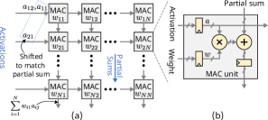
In DNNs, there are massive amounts of MAC operations. Existing digital hardware platforms use many parallel MAC units, e.g., 65,536 in the systolic array of TPU v1 (TPU, ), to accelerate DNNs. The structure of this systolic array is sketched in Fig. 1(a), while the internal structure of a MAC unit is shown in Fig. 1(b). In the systolic array, weights are preloaded and activations are streamed as inputs. The partial sum of a multiplication is propagated along a column to calculate the multiplication result of an input vector and a weight vector. Between rows and columns there are flip-flops. Therefore, the activations are shifted to match the propagation of the partial sum at the MAC units.
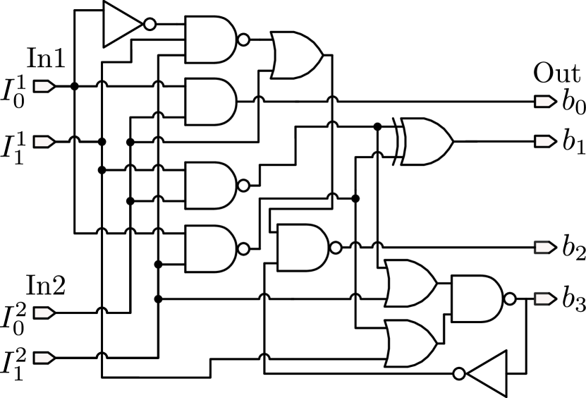
In a MAC unit above, the inputs of the multiplier are represented in two’s-complement to express integer values. The circuit of the multiplier is defined by the truth table which enumerates all the input combinations. For example, Fig. 2(a) shows the truth table of a multiplier with 2-bit signed inputs In1 and In2. The column Trad. Enc. shows the output bit sequences in the two’s complement format corresponding to decimal numbers in the last column of Fig. 2(a). From this truth table, the logic circuit for this multiplier can be synthesized as shown in Fig. 2(b). As the bit width of input operands increase, the number of rows in the truth table of a multiplier increases exponentially. Since the synthesized circuit must be able to realize all the rows in the truth table exactly, the circuit thus becomes complicated quickly. For example, an 8-bit signed multiplier can contain 417 combinational logic gates. Though approximate computing (approximate, ) can be applied to reduce the logic complexity of multipliers, this technique still uses the two’s complement format to represent the multiplication results and does not take advantage of the full potential of MAC units.
The circuit of a multiplier maps the input combinations to the output combinations. In the traditional design, the bit sequences representing the output combinations of a multiplier are predefined in the two’s complement format according to the multiplication function, as shown in the Trad. Enc. column in Fig. 2(a). However, if these bit sequences can be adjusted, the new truth table can lead to a multiplier circuit with a lower logic complexity. For example, the New Enc. column in Fig. 2(a) shows another assignment of bit sequences to represent the same output values of the multiplier, where the bit width has been increased from 4 to 5. Since the number of bits at the output of the multiplier has been increased, different bit sequences can represent the same integer value. For example, both 00111 and 01011 in the New Enc. column in Fig. 2(a) represent the same decimal value 2. From this new bit sequence assignment, a much simpler circuit can be generated, as illustrated in Fig. 2(c).
| In1 | In2 | Trad. Enc. | New Enc. | Value | |||
| 10 | 10 | 0100 | 01111 | 4 | |||
| 10 | 11 | 0010 | 00111 | 2 | |||
| 10 | 00 | 0000 | 11111 | 0 | |||
| 10 | 01 | 1110 | 10111 | -2 | |||
| 11 | 10 | 0010 | 01011 | 2 | |||
| 11 | 11 | 0001 | 00001 | 1 | |||
| 11 | 00 | 0000 | 11111 | 0 | |||
| 11 | 01 | 1111 | 10101 | -1 | |||
| 00 | 10 | 0000 | 11111 | 0 | |||
| 00 | 11 | 0000 | 11111 | 0 | |||
| 00 | 00 | 0000 | 11111 | 0 | |||
| 00 | 01 | 0000 | 11111 | 0 | |||
| 01 | 10 | 1110 | 11011 | -2 | |||
| 01 | 11 | 1111 | 11001 | -1 | |||
| 01 | 00 | 0000 | 11111 | 0 | |||
| 01 | 01 | 0001 | 11101 | 1 | |||
|
|||||||
The bit sequence assignment in Fig. 2(a) is called an encoding. The original encoding of the multiplier shown in the column Trad. Enc. is only one of the possible encodings representing the values at the output of the multiplier. Since various encodings lead to different truth tables for the multiplier, they also result in different circuit complexity after logic synthesis. Therefore, exploring the encoding can be an effective technique to obtain more efficient circuit implementation for the multiplier.
3. Encoding-based MAC Design
To identify a new encoding to simplify the MAC circuits, two challenges should be addressed. First, the number of encodings is huge, up to for an 8-bit multiplier with -bit output. For each encoding, a circuit should be generated, which leads to a very long search time. Second, the identified encoding should not make the accumulation implementation of partial sums generated by redesigned multipliers complicated. For example, the new encoding shown in the New Enc. column in Fig. 2(a) also defines the input bit combinations of an adder in a MAC operation. However, it is not an easy task to synthesize an efficient circuit for an adder with an arbitrary input encoding.
To allow a simple implementation of accumulation, we impose an additional constraint that the bits in a bit sequence have position weights. For example, we assign position weights , , , , to the bit sequences in the New Enc. column of Fig. 2(a). Accordingly, a bit sequence represents the number . These position weights are adjustable for different neural networks to maintain inference accuracy. Compared with the traditional two’s complement number system where the position weights are fixed only to power of two values, the adjustable position weights provide more flexibility for the implementation of the multipliers and adders.
3.1. Encoding-based Multiplier Design
To determine the encoding and the logic design of a multiplier with a given bit width, e.g., 8 bits, we only use single-level logic as illustrated in Fig. 2(c). This can decrease the critical path of the circuit effectively while reducing the area. Under this assumption, an output bit of the multiplier is driven by a single logic gate, which takes operand bits to the multiplier as its input. In our design, we consider the single-level logic gates SET, IN, NAND2, NAND3, AND2, OR2, NOT, XOR3, where the SET gate always outputs a high signal ‘1’ to allow a constant bias in the result to approximate the original multiplication function. The IN gate connects the input signals to output signals without any logic gate on the connections.
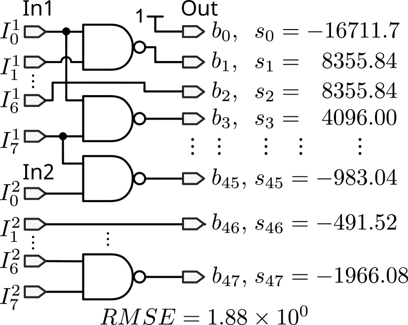
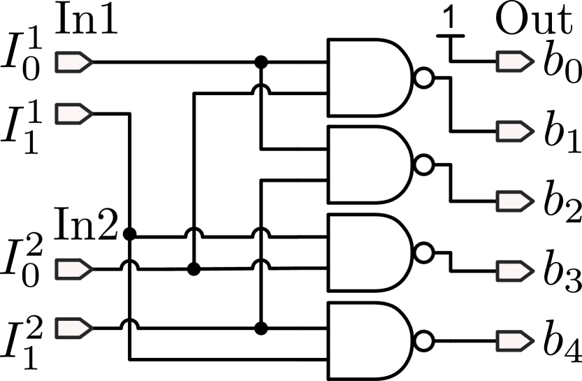
Even with the assumption of single-level logic, the search space to generate the logic for the multiplier can still be large, because for every output bit the gate type to drive it should be selected and the inputs of such a gate should be selected from the input bits of the multiplier. To address this issue, we randomly sample the gate types and the connections from the input bits to create circuit samples. In each sample, we can obtain a candidate of the circuit for the multiplier. Fig. 3 illustrates two circuit samples, where the bit width of the multiplication results is set to 48 bits. With such a sample, we can generate the output bit sequence for every bit combination of the operands of the multiplier. In other words, we can create a truth table similar to Fig. 2(a) from such a sampled circuit. Each row in this truth table corresponds to an exact value determined by output bit sequence, as illustrated in the Value column in Fig. 2(a).
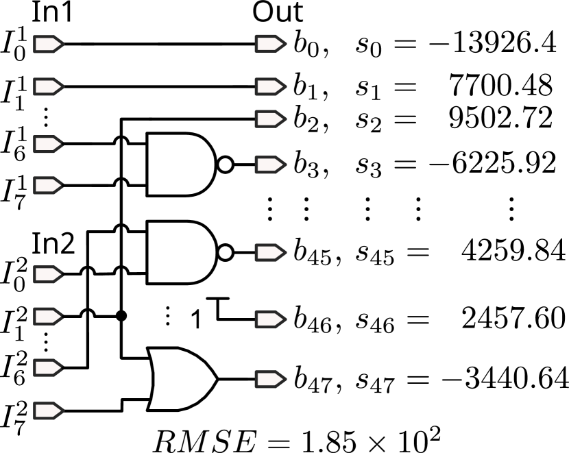
In a sampled circuit, assume that the bit sequence with bits of the th row in the truth table are expressed as , e.g., in the New Enc. column in Fig. 2(a), the value this bit sequence represents can be calculated as , where are the position weights whose exact values will be determined later. The difference between the value this bit sequence approximates and the original value is then .
When all the rows in the truth table of a sampled circuit are considered together, we can then determine the position weights by minimizing the root mean square error (RMSE) that the bit sequences approximate the original values of the multiplication results, as
| (1) |
where B is the bit sequences derived from a sampled circuit corresponding to all the rows in the truth table. s is the vector of all the position weights. v is the vector of all the original values of the multiplier, e.g., the Value column in Fig. 2(a).
After the position weights for a sampled circuit is determined as described above, we can also obtain the RMSE for each sampled circuit. We execute the sampling process for up to times and track the trend of the RMSE with the increasing number of samples. When the RMSE becomes stable, we stop the sample process and the circuit with the minimum RMSE will be returned as the circuit design for the multiplier.
The sampling process described above is based on the assumption that a bit width at the output of the new multiplier is given. To determine the minimum bit width at the output of the new multiplier, a binary search algorithm is used. Initially, the minimum and the maximum bit width are set to 16 and 128 for an 8-bit multiplier, respectively. Afterwards, the middle bit width 72 is used to execute the sampling process above. The sampled circuit candidate producing the best approximation is returned and the corresponding RMSE can be evaluated. The RMSE is compared with a target RMSE, which is determined by exhaustively evaluating various RMSEs with respect to the inference accuracy of neural networks and the one that can maintain the inference accuracy is selected. If the RMSE of the returned circuit candidate is larger than the target RMSE, the minimum bit width will be updated to the middle bit width in the next iteration and vice versa. The search algorithm terminates until the distance between the minimum and maximum bit width is equal to 0 or 1.
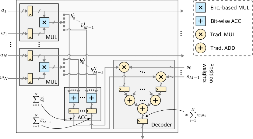
3.2. Adder Design with Encoding
Since the bit sequences at the output of the multiplier do not follow the two’s complement number system, we also need to define a new structure to implement the addition function. For the general case of accumulating the -bit outputs of multipliers, the sum can thus be expressed as , where is the th bit of the output of the th multiplier. Accordingly, the circuit to implement this sum can be designed as illustrated in Fig. 4. In this implementation, the corresponding bits of the multipliers are accumulated first and the position weights are multiplied with such accumulation results at the bottom of each column in a MAC array only once. The results of these multiplication operations are added by an adder tree to generate the data in the two’s complement format for further functions, e.g., activation and batch normalization. We call such multipliers for multiplying position weights and adders for generating two’s complement numbers as a decoder.
3.3. Design and Application of MAC Array
We deploy the encoding-based multipliers and adders to construct a MAC array with a size to execute MAC operations in DNNs efficiently, one column of which is illustrated in Fig. 4. At the inputs of each encoding-based multiplier, flip-flops are inserted to allow the reuse of inputs, similar to that in the traditional systolic array. Different from the traditional systolic array where each MAC unit has an individual adder, the adders only appear at the bottom of each column, which performs the bit-wise weighted accumulation in a column. Another difference is that there are no flip-flops for storing the multiplication result of the multipliers due to the shorter critical paths inside the encoding-based multipliers.
To execute MAC operations with the encoding-based MAC array, weights in a neural network are first loaded into the flip-flops in each multiplier. Activations are streamed as inputs. Since there are no flip-flops for storing the intermediate multiplication results in each multiplier, activations are not required to be shifted as in the traditional systolic array. Activations belonging to the inputs of a neuron can enter each column simultaneously and the results of multiplication and bit-wise accumulation are obtained after each clock cycle.
To enhance the inference accuracy of neural networks executed on the encoding-based MAC array, we further fine-tune the adjustable position weights for specific neural networks. These position weights are initially set to the values determined by minimizing the RMSE that the bit sequences approximate the original multiplication results. In fine-tuning, straight-through estimator (STE) (bengio2013estimating, ) was used for propagating gradients of encoding-based multipliers.
The encoding-based MAC array have slightly better throughput and latency than those of the traditional systolic array under the same size while achieving a much lower area cost and power consumption. Assume that a weight matrix with a size of has been loaded into the encoding-based array and the traditional MAC array. The clock period is denoted as . To finish a computation between an input matrix with a size of , the latency of the encoding-based array and the traditional MAC array are and , respectively. To evaluate the throughput, we assume that input matrices with sizes of need to be processed by the MAC arrays. The throughputs of the encoding-based array and the traditional MAC array are and , respectively. The proposed design exhibits a higher performance, and the throughputs of these designs becomes nearly the same as becomes large.
The proposed new encoding technique is not limited to simplifying the traditional multiplier in the MAC array. For example, it can process the truth table of multiplication with non-uniform quantization directly without requiring the conversion of the non-uniform encoding into the two’s complement as required in the traditional design. In such a case, the final hardware design becomes specific for neural networks with the corresponding non-uniform quantization, but the hardware cost can be reduced even further in such application-specific computing scenarios. Since the inputs of the multipliers and the final output of the MAC operations are in the original formats defined by neural networks, this new design is also compatible with the existing training and inference frameworks of neural networks.
| Size of Syst. Arr. |
|
|
|
|||||||||||
|---|---|---|---|---|---|---|---|---|---|---|---|---|---|---|
| Trad. | Prop. | Trad. | Prop. | Red. | Trad. | Prop. | Red. | |||||||
| 3232 | 16 | 48 | 0.181 | 0.163 | 9.94% | 0.239 | 0.172 | 28.03% | ||||||
| 4848 | 16 | 48 | 0.380 | 0.259 | 31.84% | 0.513 | 0.268 | 47.76% | ||||||
| 6464 | 16 | 48 | 0.652 | 0.404 | 38.07% | 0.891 | 0.416 | 53.36% | ||||||
| 128128 | 16 | 48 | 2.464 | 1.050 | 57.38% | 3.433 | 1.043 | 69.61% | ||||||
| 256256 | 16 | 48 | 9.572 | 2.854 | 70.18% | 13.473 | 2.744 | 79.63% | ||||||
| Model-Dataset | 32-FP |
|
|
|
||||||||||||||
| Orig. | Prop. | Acc. loss | Orig. | Prop. | Acc. loss | Orig. | Prop. | Acc. loss | ||||||||||
|
93.07% | 93.03% | 92.59% | 0.44% | 91.06% | 90.93% | 0.13% | 92.81% | 92.58% | 0.23% | ||||||||
|
68.82% | 68.45% | 68.27% | 0.18% | 62.60% | 62.52% | 0.08% | 67.87% | 67.19% | 0.68% | ||||||||
|
80.84% | 80.32% | 80.23% | 0.09% | 73.97% | 73.28% | 0.69% | 79.50% | 79.32% | 0.18% | ||||||||
4. Experimental Results
To verify the proposed encoding-based MAC array, we synthesized the encoded-based MAC circuit with NanGate 15 nm cell libraries (OpenCellLibrary15nm, ). These MAC circuits approximate the results of the uniformly quantized 8-bit MAC units. Such MAC circuits were then used to construct a MAC array similar to Fig. 4. In synthesizing the circuits, the clock frequency was set to 1 GHz. Power and area analysis of this hardware were conducted with Design Compiler from Synopsys. Such a MAC array can efficiently execute neural networks while maintaining a high inference accuracy. To verify this, we tested the accuracy of three neural networks together with the corresponding datasets, ResNet18-Cifar10, ResNet20-Cifar100 and ResNet50-ImageNet, using the new MAC design. These neural networks were initially trained using Pytorch, and pretrained weights were loaded from Torchvision (ImageNetpytorch, ) and public repositories on Github (Cifar10pytorch, ; pytorchCifar100, ). The learning rate of the position weights in the novel encoding for fine-tuning ResNet18, ResNet20, and ResNet50 was set to 1e-3, 1e-3, and 1e-8, respectively.
Table 1 shows the comparison between the proposed MAC array and the traditional systolic array in power consumption and area cost. Different sizes were used to verify the advantages of the hardware platform, as shown in the first column. The second and the third columns are the bit width of product, i.e., multiplication result, in the multipliers in the traditional systolic array and the bit width of the encoding-based multipliers in the proposed MAC design, respectively. The latter is determined by the search algorithm in Section 3.1. Although the bit width of the encoding-based multipliers is larger than that of the traditional one, the power consumption and the area cost of the MAC array exhibit significant advantage, because the logic to generate these intermediate bits is much simpler compared with the traditional multiplication. This advantage can be clearly seen from the last six columns in Table 1 , where the column Trad. and the column Prop. show the results of power consumption and area of the traditional MAC design and the proposed design, respectively. The columns Red. show the ratios of reduction. Besides, with the decreasing size of MAC array, the reduction of power consumption and area becomes smaller. This phenomenon results from the fact that the bit-wise accumulators and decoders at the bottom of columns incur additional area cost and thus power consumption. When the MAC array has a small size, the incurred area and power cost contributes much to the total cost.
The proposed new MAC design can execute neural networks with high inference accuracy while consuming less power. Table 2 demonstrates the inference accuracy of neural networks with three different quantization settings, namely, 8-bit uniform quantization, 4-bit non-uniform quantization for all layers (cho2021dkm, ), and 4-bit non-uniform quantization with the first and last layers using 8-bit uniform quantization (cho2021dkm, ). For the 8-bit uniform quantization, the corresponding weights and input activations can be directly processed with the MAC array. For the two settings of non-uniform quantization, the non-uniform levels are first converted to the most close levels in 8-bit uniform quantization and then such 8-bit uniform quantization levels are used for MAC operations.
The second column of Table 2 is the inference accuracy evaluated with 32-bit floating-point weights and input activations at software level. The inference accuracy of neural networks with 8-bit uniform quantization and 4-bit non-uniform quantizations at software level is shown in the third, sixth and ninth columns. According to these columns, it is clear that 8-bit uniform quantization can nearly maintain the inference accuracy with floating-point data. The first setting of 4-bit non-uniform quantization for all layers leads to a relatively large accuracy degradation due to limited data representation while the second setting including 8-bit quantization in the first and the last layers can achieve a better accuracy. The inference accuracy of neural networks executed on the proposed MAC design is shown in the fourth, seventh and tenth columns in Table 2. Due to the approximation in the proposed encoding technique, there is a slight accuracy loss compared with that at software level, as shown in the fifth, eighth and eleventh columns.
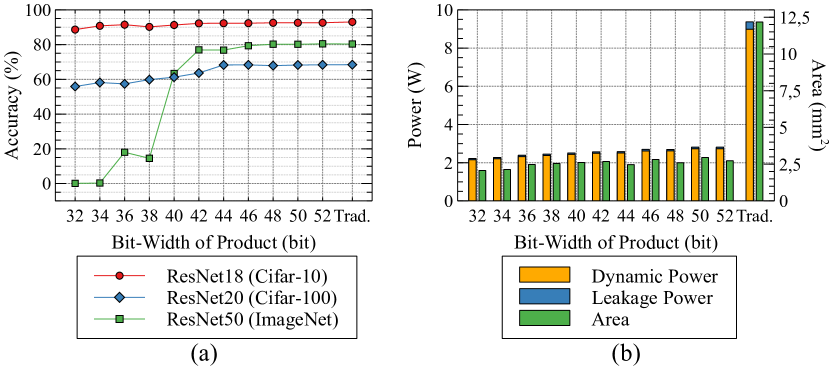
To determine the minimum bit width of product in the encoding-based multipliers, a binary search algorithm is applied. The results of this search are illustrated in Fig. 5. Fig. 5(a) shows the relationship between the bit widths and the inference accuracy of neural networks. Fig. 5(b) is the relationship between the bit widths and power consumption as well as area cost. According to Fig. 5(a), inference accuracy becomes higher with the increasing bit width of product and keeps stable around 48 bits. Accordingly, 48 bits were used for the output bit width of the product. In Fig. 5(b), power consumption and area cost increase very slowly when the bit width of product goes larger and there is no linear relationship between the bit width and the power consumption as well as area due to the randomness in the search algorithm and logic simplification in synthesis.
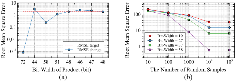
In the binary search algorithm to determine the minimum bit width of the product, a target RMSE was used as a guidance, which was set to the one that can maintain the inference accuracy of neural networks. The results of the search process are illustrated in Fig. 6(a). According to this figure, after several search iterations, the RMSE becomes stable and the minimum bit width that can achieve a RMSE smaller than a target RMSE, which is 48 bits, was selected. For a specified bit width, a given number of encoding samples, , were used to generate the encoding-based multipliers and then determine their RMSEs. To verify this, different numbers of samples were used to evaluate the RMSEs, as shown in Fig. 6(b). According to this figure, with the increasing number of samples, the RMSE is reduced and becomes stable when the sample number reaches .
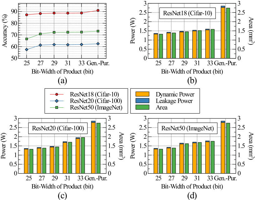
The proposed encoding technique can benefit task-specific hardware platforms more in the reduction of power consumption and area compared with general-purpose encoding-based MAC array, because the truth table of the multiplier after non-uniform quantization can be used directly for searching a new efficient multiplier design. The conversion of the non-uniform quantization into 8-bit two’s complement encoding in the traditional computing system can thus be avoided. To verify this advantage, we first trained a specific neural network with 4-bit non-uniform quantization in all layers. Afterwards, we applied the proposed binary search algorithm to determine the minimum bit width of the product for the encoding-based multipliers. The multipliers are then used to construct an MAC array with a size of 256 256 that is designed specifically to execute a given neural network.
The results are illustrated in Fig. 7. Fig. 7(a) shows that in the search of bit width for a specific neural network, e.g., ResNet18, the inference accuracy of this neural network improves as the bit width increases. When the bit width is around 31 bits, the inference accuracy becomes stable for ResNet18. This bit width is much smaller than the bit width for the 8-bit multiplier, which requires 48 bits to represent more information in the computation results. The relationship between the bit width and power consumption as well as area for ResNet18 is shown in Fig. 7(b). It can be observed that the power consumption and area of the task-specific design are smaller than those of 8-bit MAC design. Similar results on ResNet20 and ResNet50 are shown in Fig. 7(c)(d).
5. Conclusion
In this paper, we propose a novel digital MAC design based on encoding. With this technique, the complex logic in traditional multipliers can be replaced with single-level logic to reduce the critical path and area significantly. The position weights allow a bit-wise accumulation to calculate the addition result. Correspondingly, pipelining stages between rows of multipliers can be reduced to lower area cost further. With this new design, area and power consumption of MAC array can be reduced by up to 79.63% and 70.18%, respectively, compared with traditional design while the inference accuracy is still maintained. Future work will study the tradeoff between the bit width at the output of the multipliers and the complexity of the single-level as well as the multi-level logic implementation in the simplified multipliers.
References
- (1) https://openai.com/blog/chatgpt.
- (2) T. Brown et al., “Language models are few-shot learners,” in Advances in Neural Information Processing Systems (NeurIPS), vol. 33, 2020, pp. 1877–1901.
- (3) D. Patterson et al., “The carbon footprint of machine learning training will plateau, then shrink,” Computer, vol. 55, no. 7, pp. 18–28, 2022.
- (4) https://www.eia.gov/tools/faqs/faq.php?id=97&t=3.
- (5) N. P. Jouppi et al., “In-datacenter performance analysis of a tensor processing unit,” in International Symposium on Computer Architecture (ISCA), 2017.
- (6) Y. Chen, T. Chen, Z. Xu, N. Sun, and O. Temam, “Diannao family: Energy-efficient hardware accelerators for machine learning,” Communications of ACM, vol. 59, no. 11, p. 105–112, 2016.
- (7) Y.-H. Chen, T. Krishna, J. S. Emer, and V. Sze, “Eyeriss: An energy-efficient reconfigurable accelerator for deep convolutional neural networks,” IEEE Journal of Solid-State Circuits (JSSCC), vol. 52, no. 1, pp. 127–138, 2017.
- (8) S. Han, H. Mao, and W. J. Dally, “Deep compression: Compressing deep neural network with pruning, trained quantization and huffman coding,” in International Conference on Learning Representations (ICLR), 2016.
- (9) T. Liang, J. Glossner, L. Wang, S. Shi, and X. Zhang, “Pruning and quantization for deep neural network acceleration: A survey,” Neurocomputing, vol. 461, pp. 370–403, 2021.
- (10) M. Jiang, J. Wang, A. Eldebiky, X. Yin, C. Zhuo, I.-C. Lin, and G. L. Zhang, “Class-aware pruning for efficient neural networks,” in Design, Automation and Test in Europe (DATE), 2024.
- (11) R. Petri, G. L. Zhang, Y. Chen, U. Schlichtmann, and B. Li, “Powerpruning: Selecting weights and activations for power-efficient neural network acceleration,” in Design Automation Conference (DAC), 2023.
- (12) G. Hinton, O. Vinyals, and J. Dean, “Distilling the knowledge in a neural network,” Neural Information Processing Systems (NeurIPS), 2014.
- (13) Y. Han, G. Huang, S. Song, L. Yang, H. Wang, and Y. Wang, “Dynamic neural networks: A survey,” IEEE Transactions on Pattern Analysis and Machine Intelligence (PAMI), vol. 44, pp. 7436–7456, 2021.
- (14) J. Wang, B. Li, and G. L. Zhang, “Early-exit with class exclusion for efficient inference of neural networks,” in International Conference on Artificial Intelligence Circuits and Systems (AICAS), 2024.
- (15) M. Wistuba, A. Rawat, and T. Pedapati, “A survey on neural architecture search,” ArXiv, 2019.
- (16) G. Armeniakos, G. Zervakis, D. J. Soudris, and J. Henkel, “Hardware approximate techniques for deep neural network accelerators: A survey,” ACM Computing Surveys, vol. 55, pp. 1–36, 2022.
- (17) A. Gholami, S. Kim, Z. Dong, Z. Yao, M. W. Mahoney, and K. Keutzer, “A survey of quantization methods for efficient neural network inference,” ArXiv, 2021.
- (18) W. Sun, G. L. Zhang, H. Gu, B. Li, and U. Schlichtmann, “Class-based quantization for neural networks,” in Design, Automation and Test in Europe (DATE), 2023.
- (19) N. D. Gundi, T. Shabanian, P. Basu, P. Pandey, S. Roy, K. Chakraborty, and Z. Zhang, “Effort: Enhancing energy efficiency and error resilience of a near-threshold tensor processing unit,” in Asia and South Pacific Design Automation Conference (ASP-DAC), 2020, pp. 241–246.
- (20) P. Pandey, N. D. Gundi, K. Chakraborty, and S. Roy, “Uptpu: Improving energy efficiency of a tensor processing unit through underutilization based power-gating,” in Design Automation Conference (DAC), 2021, pp. 325–330.
- (21) B. Moons, R. Uytterhoeven, W. Dehaene, and M. Verhelst, “14.5 envision: A 0.26-to-10tops/w subword-parallel dynamic-voltage-accuracy-frequency-scalable convolutional neural network processor in 28nm fdsoi,” in International Solid-State Circuits Conference (ISSCC), 2017, pp. 246–247.
- (22) J. Nunez-Yanez, “Energy proportional neural network inference with adaptive voltage and frequency scaling,” IEEE Transactions on Computers (TC), vol. 68, no. 5, pp. 676–687, 2019.
- (23) D. Miyashita, E. H. Lee, and B. Murmann, “Convolutional neural networks using logarithmic data representation,” arXiv, 2016.
- (24) M. Valueva, N. Nagornov, P. Lyakhov, G. Valuev, and N. Chervyakov, “Application of the residue number system to reduce hardware costs of the convolutional neural network implementation,” Mathematics and Computers in Simulation, vol. 177, pp. 232–243, 2020.
- (25) Y. Bengio, N. Léonard, and A. Courville, “Estimating or propagating gradients through stochastic neurons for conditional computation,” arXiv, 2013.
- (26) M. Cho, K. Alizadeh-Vahid, S. Adya, and M. Rastegari, “Dkm: Differentiable k-means clustering layer for neural network compression,” in International Conference on Learning Representations (ICLR), 2021.
- (27) “15nm Open-Cell library and 45nm freePDK,” https://si2.org/open-cell-library/.
- (28) “Pretrained ImageNet models,” https://pytorch.org/vision/stable/models.html.
- (29) “Pretrained Cifar10 models,” https://github.com/huyvnphan/PyTorch_CIFAR10.
- (30) “Pretrained Cifar100 models,” https://github.com/weiaicunzai/pytorch-cifar100.