Bimanual Manipulation of Steady Hand Eye Robots with Adaptive Sclera Force Control: Cooperative vs. Teleoperation Strategies
Abstract
Performing intricate eye microsurgery, such as retinal vein cannulation (RVC), as a potential treatment for retinal vein occlusion (RVO), without the assistance of a surgical robotic system is very challenging to do safely. The main limitation has to do with the physiological hand tremor of surgeons. Robot-assisted eye surgery technology may resolve the problems of hand tremors and fatigue and improve the safety and precision of RVC. The Steady-Hand Eye Robot (SHER) is an admittance-based robotic system that can filter out hand tremors and enables ophthalmologists to manipulate a surgical instrument inside the eye cooperatively. However, the admittance-based cooperative control mode does not address crucial safety considerations, such as minimizing contact force between the surgical instrument and the sclera surface to prevent tissue damage. An adaptive sclera force control algorithm was proposed to address this limitation using an FBG-based force-sensing tool to measure and minimize the tool-sclera interaction force. Additionally, features like haptic feedback or hand motion scaling, which can improve the safety and precision of surgery, require a teleoperation control framework. A single-manual adaptive teleoperation control mode was implemented on SHER 2.1 in previous work for the first time in robot-assisted retinal microsurgery. We extended the previous work into a bimanual adaptive teleoperation (BMAT) control mode using SHER 2.0 and SHER 2.1 and compared its performance with a bimanual adaptive cooperative (BMAC) mode. Both BMAT and BMAC modes were tested in sitting and standing postures during a vessel-following experiment under a surgical microscope. It is shown, for the first time to the best of our knowledge in robot-assisted retinal surgery, that integrating the adaptive sclera force control algorithm with the bimanual teleoperation framework enables surgeons to safely perform bimanual telemanipulation of the eye without over-stretching it, even in the absence of registration between the two robots. Experimental results demonstrate the effectiveness of the proposed BMAT control framework.
I INTRODUCTION
Retinal vein occlusion (RVO) has been identified as the second most prevalent potentially blinding retinal vascular disease, impacting an estimated 28 million individuals globally, according to a meta-analysis study [1]. This condition stems from the occlusion of a retinal vein, leading to eye problems including vision loss. Presently, there is no established standard for directly treating RVO with a surgical approach. Retinal vein cannulation (RVC) has been attempted in order to deliver a therapeutic agent directly into the affected vein [2], however, its applicability is highly challenging due to the micron scale of retinal veins and human hand tremor [3]. The problem of scale is presently best addressed with the assistance of a surgical robotic system. Of note, the diameter of the largest retinal veins is on the order of m [4], and the root mean square (RMS) amplitude of hand tremor for an ophthalmic surgeon is measured to be m [5].
Several surgical robotic systems have been developed to filter out physiological hand tremors and improve the safety of retinal surgery. Some examples of these systems include the Steady Hand Eye Robot (SHER) [6, 7], Preceyes [8], to name a few [9, 10, 11].
The SHER 2.0 and SHER 2.1 are two robot versions developed at Johns Hopkins University. The main control algorithm implemented on SHERs is an admittance-based control where the user and the robot cooperatively manipulate a surgical tool. Using a force/torque sensor attached to the robot handle, the exerted force by the user is measured and converted to a desired end-effector velocity to control the robot [7]. An important limitation of this control algorithm is that the force/torque sensor is not sensitive enough to measure the minimal interaction force existing on the surgical instrument at the sclera entry (RCM), which could result in applying excessive force to the sclera distorting and potentially causing damaging. To overcome this issue, Ebrahimi et al. proposed an adaptive sclera force control algorithm [12] using an FBG-based force-sensing tool to automatically minimize the sclera force and keep it within a suggested safe range of 120 mN [13]. Notably, FBG sensors have applications in flexible needles or continuum robots, serving purposes such as shape sensing [14] or force sensing [15]. A comparison of the adaptive force control algorithm and the admittance-based control algorithm performance was conducted using a vessel-following experiment. An eye phantom was used where the SHER 2.1 held the primary force-sensing surgical tool and cooperatively manipulated the user’s dominant hand. Simultaneously, a conventional surgical instrument was directly held by the non-dominant hand, serving as a secondary tool for re-orienting the eye under a surgical microscope [12]. Despite reducing the applied force to the sclera by the dominant hand compared to the admittance-based control mode, controlling the force magnitude on the secondary hand-held tool is impossible, and applying excessively unsafe force to the sclera cannot be avoided. Also, this evaluation took place within a single-manual cooperative control mode without teleoperation capability. Integrating this adaptive force control algorithm in a teleoperation modality has the potential to offer surgeons advanced capabilities, contributing to an improvement in patient safety. Esfandiari et al. implemented this algorithm in a teleoperation modality and compared its performance with a cooperative control mode in a single-manual framework [16].
In this work, we extended the previous single-manual teleoperation framework to a bimanual adaptive teleoperation control framework integrated with an adaptive sclera force control algorithm on the SHER 2.0 and the SHER 2.1 systems using two force-sensing surgical instruments. This framework enables surgeons to safely conduct bi-manual teleoperation on the eye, preventing any stretching of the eye, even without registering the two robots. For the first time in robot-assisted retinal microsurgery applications, we compared the performance of the proposed bimanual adaptive teleoperation control mode and a bimanual adaptive cooperative control mode integrated with the same adaptive force control algorithm. This evaluation occurred during a vessel-following experiment on an eye phantom under a surgical microscope for both sitting and standing postures for each control mode. The objective was to assess and compare the performance of the BMAT and BMAC control modes and also the effect of user’s posture on their performance.
The two FBG-based force-sensing surgical instruments are calibrated using a method outlined by [15]. This calibration enabled the estimation of the tip force, sclera force, and insertion depth by measuring the wavelength shifts of nine FBG sensors attached to each tool.
The remaining sections of this paper are organized as follows. Methods are discussed in Section II. Section III describes the experimental setup and the experiment procedure. The experimental results are analyzed and discussed in Section IV. Finally, a conclusion is made in Section V.
II Methods
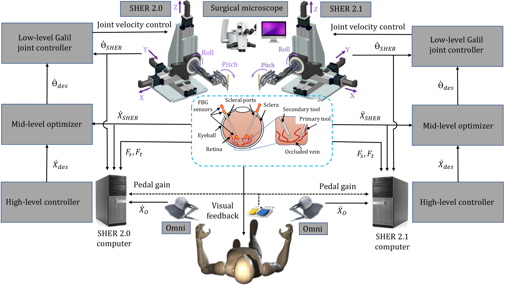
The objective of this experiment is to extend a previously developed adaptive teleoperation control mode [16] to two eye robots, the SHER 2.0 and SHER 2.1, and to assess the performance of the two control frameworks: bimanual adaptive cooperative mode and bimanual adaptive teleoperation mode (see Fig. 1), in both sitting and standing postures. In both control modes, the sclera force magnitude is automatically controlled (without the user’s commands) by an adaptive force control algorithm [12] to avoid stretching and damaging the sclera. Following the suggestion of our clinical lead, we conducted a "vessel-following" experiment, a prototypical task in retinal surgery [17]. The experimental setup prepared to perform the vessel-following experiment provides a measurement and recording of SHERs’ kinematic information, the user’s hand force/torque during interaction with the SHERs’ handle, and the force applied to the surgical tool at the sclera point and the tooltip.
II-A Adaptive Force Control of the SHER
In this control algorithm, if each of the measured sclera force components, and , surpasses the specified safety threshold, , the robot is directed along a safe sclera force trajectory [18]. By estimating the stiffness of the sclera tissue, denoted by or , the desired sclera force trajectories, and , can be calculated using Equations (1) and (2), respectively:
| (1) |
| (2) |
where represents the time at which surpasses the safe threshold.
The desired linear velocities of the SHER’s end-effector along the and directions in the body frame can be determined by the adaptive force controller using Equations (3) and (4):
| (3) |
| (4) |
where denotes the sclera force error, and and represent constant gains for the adaptation law and the force tracking error, respectively. stands for the estimated tissue compliance, and is the derivative of . This adaptive sclera force control algorithm applies to both cooperative and teleoperation control modalities. In the cooperative control mode, the remaining components of the SHER end-effector velocity are generated by the admittance-based controller, whereas in teleoperation control mode, they are derived from the PHANTOM Omni’s end-effector velocity (mapped to the SHER body coordinate ). The proposed teleoperation control mode, integrated with an adaptive sclera force control algorithm, consists of three primary components: a high-level controller, a mid-level optimizer with joint constraints, and a low-level joint velocity controller (Galil).
The high-level controller consists of two primary components: Firstly, there is a kinematic controller that translates the end-effector velocity of the Omni, denoted as , into the SHER’s body coordinate as . It is then pre-multiplied by , a user-defined motion scaling matrix, to provide an intuitive motion on the SHER end-effector velocity, i.e., . Secondly, an adaptive sclera force controller that receives input from the sclera force components and , which are measured in the body coordinate by the force-sensing instrument. This controller generates the desired adaptive end-effector velocity in the SHER body coordinate, denoted as in Equation (3).
This hybrid kinematic-force control method determines the desired SHER velocity by switching between and based on the magnitude of the sclera force. When the scleral force components fall below a safe threshold , the SHER is controlled based on kinematic teleoperation using the Omni velocity ; otherwise, the adaptive force controller takes charge, enforcing the SHER’s end-effector velocity through to minimize scleral force components. As a result, the desired end-effector velocity of SHER, , is generated based on the following hybrid kinematic-force control algorithm:
| (5) |
in which ( or ) is a binary variable automatically set by the control switching policy (Algorithm 1) based on the magnitude of sclera force components ( or ). means the adaptive force control algorithm for the corresponding sclera force component ( or ) is activated. Otherwise, when , the adaptive force control algorithm gets deactivated, and Equation (5) becomes equivalent to the kinematic control .
The mid-level optimizer computes the optimal desired joint velocities, denoted as , for the SHER while accounting for its joint limit constraints. Finally, the low-level Galil joint velocity controller generates the necessary control commands to reach the desired joint velocities. Other signals include (actual joint velocities of the SHER), (actual end-effector velocity in the spatial coordinate of the SHER), and (tooltip force) (see Fig. 1).
III Experiments
III-A Experimental Setup
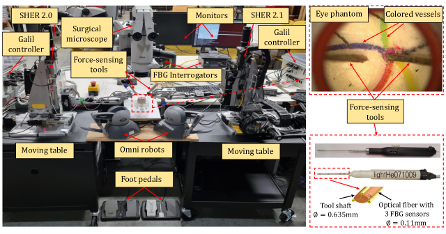
The setup components comprised the SHER 2.1 on the right holding the primary force-sensing tool, the SHER 2.0 on the left holding the secondary force-sensing tool, two robot controllers (Galil motion controllers, CA, USA), two PHANTOM Omni robots (SensAble Technologies Inc., MA, USA), two ATI force sensors (Nano17, ATI Industrial Automation, Apex, NC, USA), two force-sensing tools with three optical fiber channels attached to each tool shaft and a total of nine FBG sensors (Technica Optical Components, China) on the three channels, an FBG interrogator (HYPERION si155, Luna) for the primary force-sensing tool and another FBG interrogator (sm130, Micron Optics, Inc.) for the secondary fore-sensing tool, an eye phantom, an armrest, and a surgical microscope (Leica Microsystems) (see Fig.2). All these devices were interconnected to two main computers for the two robots through a TCP-IP connection.
Two 6-DoF ATI Nano 17 force sensors are integrated into the SHERs’ end-effector to measure the user hand’s force and torque exerted on the robot handle and to control the robot in the cooperative mode with an admittance-based control algorithm [7]. For measuring the sclera force applied to the eye phantom by the two surgical instruments, two FBG force-sensing tools are employed. The tool shaft features three FBG fibers arranged at 120-degree intervals, housing a total of nine FBG sensors distributed along the three fibers [19] (see Fig. 2). Optical signals from these FBG sensors are received by the two FBG interrogators, which then convert them into force readings at the sclera point and the tooltip. The force read at the sclera point has two components, and , perpendicular to the tool shaft and are used in the adaptive sclera force control algorithm to always maintain the sclera force level below a safe threshold. The two PHANTOM Omnis serve as a joystick controller for the bimanual teleoperation of SHER 2.0 and SHER 2.1. The eye phantom, designed as an anatomical eye model replicating critical features of a natural human eye, is utilized in this experiment.
III-B Experimental Procedure
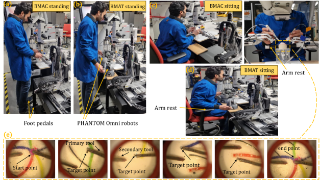
To assess the performance of the two bimanual control modes, BMAC and BMAT, the user is asked to conduct a vessel-following experiment in sitting and standing postures for each control mode (see Fig. 3a-d). The task involves tracking a colored trajectory on the retinal surface of an eye phantom that simulates retinal veins. The colored trajectory comprises four different colors: red, green, blue, and yellow. A pin is attached at the end of each colored vessel to specify a target point and the user is asked to touch the pin with the tooltip. This requires pinpoint accuracy in tool use by the user. The user starts the experiment by approaching the tip of the primary tool, manipulated by the dominant hand, to the start point at the intersection of the four colored vessels, tracking the four colored vessels in a random order, and touching the target pins at the end of each colored vessel. Once all colors are tracked, the user returns to the intersection point (see Fig. 3e). This procedure is considered one trial. More specific details of the procedure are outlined in [17]. The experiment includes 5 sets of tests collected on five different days. For each test, 10 trials are repeated following a random order of colored vessels, resulting in 50 trials for each mode, namely, standing BMAC, sitting BMAC, standing BMAT, and sitting BMAT. To optimize visualization, all trials are conducted under a surgical microscope with an illuminator.
In the bimanual cooperative control mode, the user holds the tool handle, and the robots are manipulated in a direct cooperation manner (Figs. 3a, 3c). In contrast, there is an indirect interaction between the user and the SHERs through the PHANTOM Omni interfaces in the bimanual teleoperation mode. Two foot-pedals separately activate each robot. The more the foot pedal is pushed, the less stiffness is observed in the SHER handle and the surgical instrument. During the sitting BMAC and sitting BMAT, the user’s hand is stabilized by an armrest to further reduce the hand tremor (see Figs. 3c, 3d), whereas, this armrest is lacking in the standing postures. Regardless of the control mode, the user uses the dominant hand to manipulate the primary force-sensing tool and the non-dominant hand to manipulate a secondary tool for re-orientation of the eye phantom to reach optimum visualization under the microscope. It’s noteworthy that bimanual manipulation is a standard method of performing retinal surgery. All kinematic and force information measured from the robots, the ATI force sensors, and the FBG-based force-sensing tools for each vessel-following trial are recorded in separate .csv files and subsequently analyzed using MATLAB. The statistical analyses were performed using a paired t-test, MATLAB’s ttest2() function, assuming unequal variance (Welch’s t-test). Statistical significance is inferred when p0.05.
![[Uncaptioned image]](/html/2402.18088/assets/x7.png)
| Standing BMAC vs. Sitting BMAC | ||||
|---|---|---|---|---|
| p-value | Mean sclera force | Max sclera force | Mean completion time | of time force over 120 mN |
| DH | 0.0259 | 5.594e-05 | 0.0084 | 9.722e-05 |
| NDH | 1.585e-4 | 5.777e-9 | 0.0084 | 8.679e-05 |
| Standing BMAT vs. Sitting BMAT | ||||
|---|---|---|---|---|
| p-value | Mean sclera force | Max sclera force | Mean completion time | of time force over 120 mN |
| DH | 3.788e-10 | 1.779e-12 | 6.213e-18 | 0.0068 |
| NDH | 2.579e-08 | 1.948e-15 | 6.213e-18 | 0.0016 |
| Sitting BMAC vs. Sitting BMAT | ||||
|---|---|---|---|---|
| p-value | Mean sclera force | Max sclera force | Mean completion time | of time force over 120 mN |
| DH | 0.0012 | 1.564e-08 | 0.0063 | 0.0040 |
| NDH | 0.0187 | 0.1621 | 0.0063 | 0.1732 |
IV Experimental Results and Discussion
To the best of our knowledge, the implementation of a bimanual adaptive teleoperation control mode integrated with an adaptive sclera force control algorithm on a microsurgical robotic system used for retinal microsurgery applications, in specific on the SHER 2.0 and SHER 2.1, is unprecedented. The performance of the proposed BMAT mode is compared with a BMAC mode in sitting and standing postures for the user by considering several important metrics related to patient safety and surgeons’ comfort. For example, some factors, having to do with patient safety, including mean and maximum sclera force and the percentage of aggregate completion times in which the recorded sclera force exceeded the safety threshold of 120 mN are reported for both dominant and non-dominant hand for all four control modes. Other factors related to surgeons’ intuition and comfort are also reported such as human-robot interaction force/torque and task completion time (Table I). The completion time is also of great importance which determines the general operational time and cost. Of note, these factors are analyzed and reported for a single expert user and may not be extrapolated to non-expert users who are not at their learning curve plateau [20].
The user, in both sitting and standing postures, is supposed to follow a random order of colored vessel trajectory while approaching the tooltip as close as possible to the bottom of the eye phantom without touching it and guide the tooltip toward a target pin attached to the end of each vessel and slightly touch it by the tooltip.
IV-A Sclera Force Control Performance
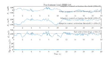
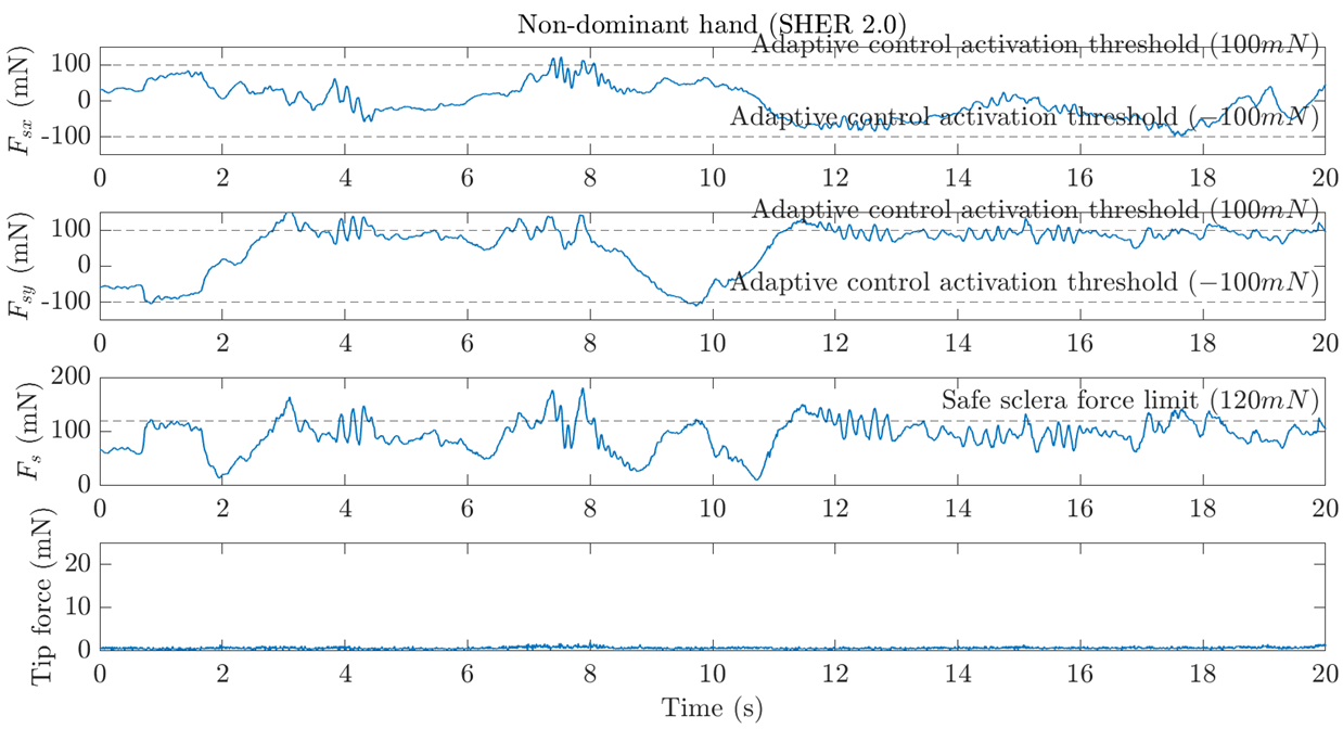
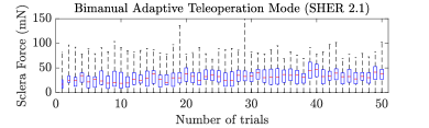
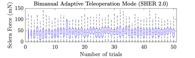
The adaptive sclera force control algorithm dynamically adjusts the SHER 2.0 and SHER 2.1 end-effector velocity to maintain the sclera force below a safe threshold of 120 mN. This feature enables the surgeon to safely manipulate the eye without applying unsafe force to the sclera. Using this technique, it is possible to safely perform bimanual robot manipulation of the eye without registering the two robots, yet avoid stretching the eye during bimanual manipulation. Figure 4 describes an example of the functionality of the sclera force control algorithm during sitting BMAT control mode for both dominant and non-dominant hands. It is observed that once the sclera force reaches the 100 mN threshold, the adaptive sclera force control algorithm gets activated and tries to minimize the sclera force components, and , along a desired exponentially decaying force trajectory. The proposed safe limit for sclera force is 120 mN [13]. The 100 mN threshold is selected for activating the adaptive force control to provide a 20 mN offset before the safe limit. The presence of four peaks in the tip force data for the dominant hand (Fig. 4a) indicates that the tooltip made contact with the four target points (pins) located at the ends of the colored vessels. Also, an example of the mean sclera force for all 50 trials for the sitting BMAT control mode is provided in Fig. 5, which indicates that the user showed a consistent performance in this mode for both dominant and non-dominant hands. Similar performance is observed for the other three control/posture modes.
Here, a comparison is made between the standing and sitting postures for each of the two BMAC and BMAT control modes, and also between the sitting BMAC and the sitting BMAT (p-values are reported in Tables II – IV) to compare the performance of BMAC and BMAT and to examine the effects of user’s posture on their performance.
IV-B Standing BMAC vs. Sitting BMAC
For example, by comparing the standing BMAC and sitting BMAC, it is observed that the user applied a significantly smaller maximum force of 185.14 21.93 by his dominant hand during the sitting BMAC compared to this value in the standing BMAC which is 245.57 23.07 (p 0.05). This difference is also significant for the non-dominant hand. The percentage of aggregate time when the sclera force is above 120 mN for the dominant hand is 0.45 0.07 for the sitting BMAC and 2.14 for the standing BMAC (p 0.05). Task completion time is also significantly reduced from 30.81 5.35 for the standing BMAC to 23.21 14.8 for the sitting BMAC (p = 0.0084) (Tables I, II).
IV-C Standing BMAT vs. Sitting BMAT
Similarly, by comparing the sitting BMAT and standing BMAT, it is observed that the user demonstrated better performance sitting. For example, the mean sclera force for the non-dominant hand during sitting BMAT is 44.84 5.39, whereas this value for the standing BMAT is 62.77 22.26 (p0.05), or the maximum sclera force for the dominant hand in the standing BMAT is 290.49 38.89 while this value is reduced to 189.92 17.64 for the sitting BMAT (p0.05). Similar improvement is also noticed for the mean completion time and the percentage of aggregate time when sclera force is above 120 mN (see Tables I, III). Based on these findings, we conclude that the user outperforms in the sitting posture because the arms are stabilized using an armrest, reducing hand tremors and fatigue. Furthermore, it is difficult to handle both foot pedals in standing mode as the user is supposed to hold their weight on the heel and pivot to push the pedals. Sometimes the user did not handle the pedals efficiently, especially the left one which is related to the non-dominant hand. This resulted in higher stiffness of the robots and, therefore, higher maximum sclera force. Although, the sitting posture allows a superior performance that makes it a preferred option for robot-assisted retinal microsurgery, however, the standing posture also allows acceptable and safe performance, which could potentially be used for other surgeries during which the surgeons may decide to partly stand during the operation such as microvascular Anastomosis [21].
IV-D Sitting BMAC vs. Sitting BMAT
Finally, by comparing the results of the BMAT and the BMAC modes in the sitting posture (Tables I, IV), it is observed that bimanual adaptive teleoperation showed comparable or better performance to the bimanual adaptive cooperative mode. For example, the mean sclera force for the dominant hand for the sitting BMAT is 32.04 4.84, which is less than the value for the sitting BMAC (35.79 5.84, p = 0.0012). Also, the percentage of aggregate time with a scleral force higher than 120 mN is less for the sitting BMAT (0.01 7.93e-4) as compared to the sitting BMAC (0.45 0.07, p = 0.004). This demonstrates lower scleral forces with a sitting BMAT. This could be, in part, due to the slower end-effector velocity during the teleoperation mode compared to the cooperative mode, which in turn results in a longer task completion time for the sitting BMAT mode (26.53 6.47 s) compared to the sitting BMAC mode (23.21 14.8 s, p = 0.0063). The maximum sclera force for both dominant and non-dominant hands for the sitting BMAT is higher than those of the sitting BMAC. For example, for the dominant hand, the value for the sitting BMAC is 185.14 21.93 mN while this value for the sitting BMAT is slightly higher, 189.92 17.64 mN. Based on our understanding, this has to do with the repositioning capability of the teleoperation mode. In the cooperative mode, the user can finish the task by holding the pedals during the entire vessel-following trial, whereas, during the teleoperation mode, the motion scaling capability necessitates several repeated unclutching, repositioning of the Omni handles, and clutching to follow a trajectory. This results in a higher stiffness at the SHERs’ handle and the surgical instrument at the beginning of each clutching, which resulted in a higher maximum sclera force for the BMAT mode; however, it is still on the same level of magnitude as the BMAC mode.
Therefore, based on the observed results, the adaptive bimanual teleoperation control mode demonstrated the desired performance during the vessel-following experiment and could be a promising technology with new capabilities to improve surgeons’ comfort, dexterity, and patients’ safety. The effectiveness of the proposed BMAT control mode should be further examined using other types of biological models, such as chicken embryo or pig eye, in addition to this phantom eye model. Moreover, adding haptic force feedback to the teleoperation mode provides the surgeons with a better understanding of the sclera force level and may improve the safety of surgery.
V Conclusion
This work performed a vessel-following experiment on a bimanual adaptive teleoperation framework with an adaptive sclera force control algorithm on SHER 2.0 and SHER 2.1 using two force-sensing tools. This was a first in robot-assisted retinal surgery applications. The tools were equipped with FBG sensors capable of measuring the force at the tool sclerotomy and the tooltip. The performance of this bimanual teleoperation mode was compared with a bimanual cooperative mode utilizing a single expert user by doing a vessel-following experiment inside an eye phantom for two sitting and standing postures. Both surgical tools, including the secondary tool used for rotating the eyeball, are force-sensing tools that provide sclera force measurements for the adaptive force control algorithm to adjust scleral forces automatically to maintain them below a safe threshold. Using this force control technique, it is possible to perform bimanual robotic surgery on the eye without registering the two robots.
Also, a comparison between the bimanual teleoperation and the bimanual cooperative modes in the sitting posture demonstrates that the bimanual teleoperation mode shows comparable performance to the bimanual cooperative mode and can potentially improve the safety and precision of surgery by providing surgeons with additional capabilities, including motion scaling and repositioning.
In the future, we intend to add haptic feedback to reflect the sclera force on the user’s hand and conduct a multi-user study to further compare the BMAT control mode equipped with haptic feedback and the BMAC control mode.
References
- [1] P. Song, Y. Xu, M. Zha, Y. Zhang, and I. Rudan, “Global epidemiology of retinal vein occlusion: a systematic review and meta-analysis of prevalence, incidence, and risk factors,” Journal of global health, vol. 9, no. 1, 2019.
- [2] K. Willekens, A. Gijbels, L. Schoevaerdts, L. Esteveny, T. Janssens, B. Jonckx, J. H. Feyen, C. Meers, D. Reynaerts, E. Vander Poorten et al., “Robot-assisted retinal vein cannulation in an in vivo porcine retinal vein occlusion model,” Acta ophthalmologica, vol. 95, no. 3, pp. 270–275, 2017.
- [3] S. Singh and C. Riviere, “Physiological tremor amplitude during retinal microsurgery,” in Proceedings of the IEEE 28th Annual Northeast Bioengineering Conference (IEEE Cat. No. 02CH37342). IEEE, 2002, pp. 171–172.
- [4] D. Goldenberg, J. Shahar, A. Loewenstein, and M. Goldstein, “Diameters of retinal blood vessels in a healthy cohort as measured by spectral domain optical coherence tomography,” Retina, vol. 33, no. 9, pp. 1888–1894, 2013.
- [5] C. N. Riviere and P. S. Jensen, “A study of instrument motion in retinal microsurgery,” in Proceedings of the 22nd Annual International Conference of the IEEE Engineering in Medicine and Biology Society (Cat. No. 00CH37143), vol. 1. IEEE, 2000, pp. 59–60.
- [6] B. Mitchell, J. Koo, I. Iordachita, P. Kazanzides, A. Kapoor, J. Handa, G. Hager, and R. Taylor, “Development and application of a new steady-hand manipulator for retinal surgery,” in Proceedings 2007 IEEE International Conference on Robotics and Automation. IEEE, 2007, pp. 623–629.
- [7] A. Üneri, M. A. Balicki, J. Handa, P. Gehlbach, R. H. Taylor, and I. Iordachita, “New steady-hand eye robot with micro-force sensing for vitreoretinal surgery,” in 2010 3rd IEEE RAS & EMBS International Conference on Biomedical Robotics and Biomechatronics. IEEE, 2010, pp. 814–819.
- [8] T. Meenink, G. Naus, M. de Smet, M. Beelen, and M. Steinbuch, “Robot assistance for micrometer precision in vitreoretinal surgery,” Investigative ophthalmology & visual science, vol. 54, no. 15, pp. 5808–5808, 2013.
- [9] Y. Ida, N. Sugita, T. Ueta, Y. Tamaki, K. Tanimoto, and M. Mitsuishi, “Microsurgical robotic system for vitreoretinal surgery,” International journal of computer assisted radiology and surgery, vol. 7, pp. 27–34, 2012.
- [10] M. A. Nasseri, M. Eder, S. Nair, E. Dean, M. Maier, D. Zapp, C. P. Lohmann, and A. Knoll, “The introduction of a new robot for assistance in ophthalmic surgery,” in 2013 35th Annual International Conference of the IEEE Engineering in Medicine and Biology Society (EMBC). IEEE, 2013, pp. 5682–5685.
- [11] E. Vander Poorten, C. N. Riviere, J. J. Abbott, C. Bergeles, M. A. Nasseri, J. U. Kang, R. Sznitman, K. Faridpooya, and I. Iordachita, “Robotic retinal surgery,” in Handbook of robotic and image-guided surgery. Elsevier, 2020, pp. 627–672.
- [12] A. Ebrahimi, M. G. Urias, N. Patel, R. H. Taylor, P. Gehlbach, and I. Iordachita, “Adaptive control improves sclera force safety in robot-assisted eye surgery: A clinical study,” IEEE Transactions on Biomedical Engineering, vol. 68, no. 11, pp. 3356–3365, 2021.
- [13] A. Ebrahimi, C. He, M. Roizenblatt, N. Patel, S. Sefati, P. Gehlbach, and I. Iordachita, “Real-time sclera force feedback for enabling safe robot-assisted vitreoretinal surgery,” in 2018 40th Annual International Conference of the IEEE Engineering in Medicine and Biology Society (EMBC). IEEE, 2018, pp. 3650–3655.
- [14] G. Amirkhani, A. Goodridge, M. Esfandiari, H. Phalen, J. H. Ma, I. Iordachita, and M. Armand, “Design and fabrication of a fiber bragg grating shape sensor for shape reconstruction of a continuum manipulator,” IEEE Sensors Journal, 2023.
- [15] X. He, M. Balicki, P. Gehlbach, J. Handa, R. Taylor, and I. Iordachita, “A multi-function force sensing instrument for variable admittance robot control in retinal microsurgery,” in 2014 IEEE International Conference on Robotics and Automation (ICRA). IEEE, 2014, pp. 1411–1418.
- [16] M. Esfandiari, J. W. Kim, B. Zhao, G. Amirkhani, M. Hadi, P. Gehlbach, R. H. Taylor, and I. Iordachita, “Cooperative vs. teleoperation control of the steady hand eye robot with adaptive sclera force control: A comparative study,” arXiv preprint arXiv:2312.01631, 2023.
- [17] C. He, N. Patel, A. Ebrahimi, M. Kobilarov, and I. Iordachita, “Preliminary study of an rnn-based active interventional robotic system (airs) in retinal microsurgery,” International journal of computer assisted radiology and surgery, vol. 14, pp. 945–954, 2019.
- [18] N. Patel, M. Urias, A. Ebrahimi, R. H. Taylor, P. Gehlbach, and I. Iordachita, “Force-based control for safe robot-assisted retinal interventions: In vivo evaluation in animal studies,” IEEE Transactions on Medical Robotics and Bionics, vol. 4, no. 3, pp. 578–587, 2022.
- [19] C. He, E. Yang, and I. Iordachita, “Dual-stiffness force-sensing cannulation tool for retinal microsurgery,” in 2019 41st Annual International Conference of the IEEE Engineering in Medicine and Biology Society (EMBC). IEEE, 2019, pp. 3212–3216.
- [20] B. Zhao, M. Esfandiari, D. E. Usevitch, P. Gehlbach, and I. Iordachita, “Human-robot interaction in retinal surgery: A comparative study of serial and parallel cooperative robots,” arXiv preprint arXiv:2304.00213, 2023.
- [21] C. M. Harris, A. O. Mitchell, and R. M. Laughlin, “Microvascular principles,” Atlas of Operative Oral and Maxillofacial Surgery, pp. 895–900, 2022.