The Architecture of Sponge Choanocyte Chambers Maximizes
Mechanical Pumping Efficiency
Abstract
Sponges, the basalmost members of the animal kingdom, exhibit a range of complex architectures in which microfluidic channels connect multitudes of spherical chambers lined with choanocytes, flagellated filter-feeding cells. Choanocyte chambers can possess scores or even hundreds of such cells, which drive complex flows entering through porous walls and exiting into the sponge channels. One of the mysteries of the choanocyte chamber is its spherical shape, as it seems inappropriate for inducing directional transport since many choanocyte flagella beat in opposition to such a flow. Here we combine direct imaging of choanocyte chambers in living sponges with computational studies of many-flagella models to understand the connection between chamber architecture and directional flow. We find that those flagella that beat against the flow play a key role in raising the pressure inside the choanocyte chamber, with the result that the mechanical pumping efficiency, calculated from the pressure rise and flow rate, reaches a maximum at a small outlet opening angle. Comparison between experimental observations and the results of numerical simulations reveal that the chamber diameter, flagellar wave number and the outlet opening angle of the freshwater sponge E. muelleri, as well as several other species, are related in a manner that maximizes the mechanical pumping efficiency. These results indicate the subtle balances at play during morphogenesis of choanocyte chambers, and give insights into the physiology and body design of sponges.
I Introduction
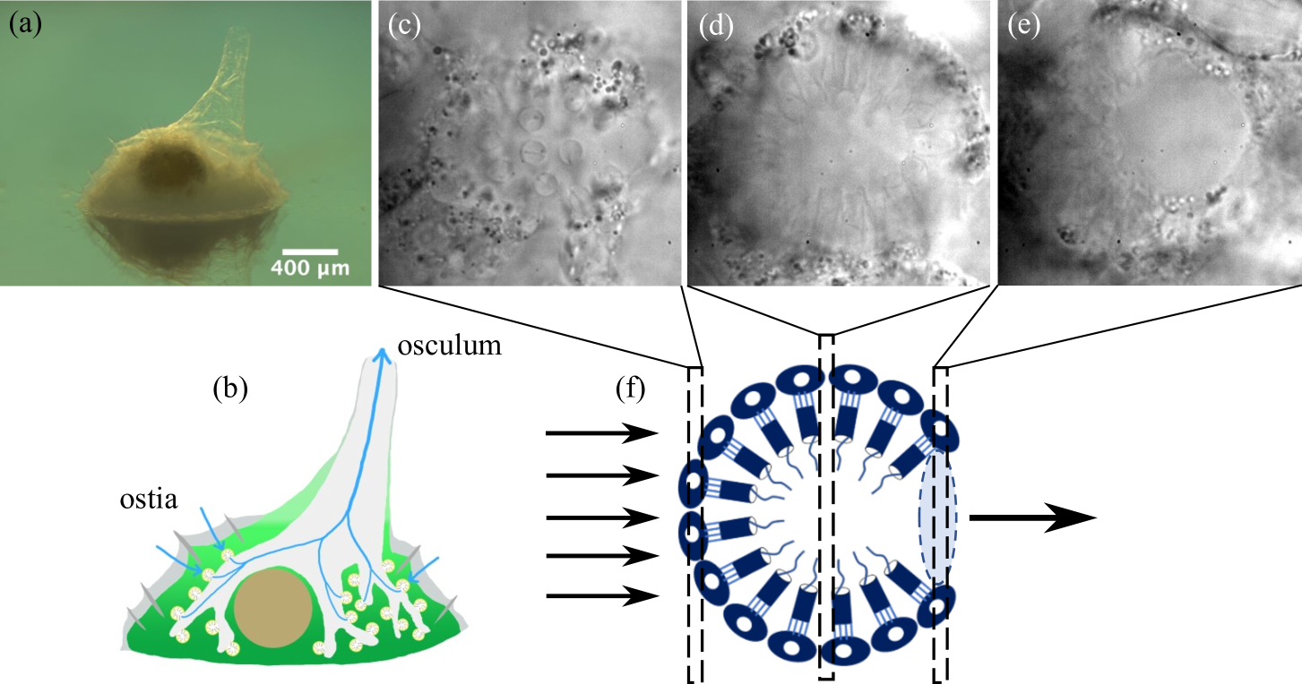
Sponges are among the oldest multicellular animals, with sponge-like fossils having been found that date as far back as 550-760 million years [1]. As filter feeders with a distinct pump-filter apparatus, sponges (phylum Porifera) can process several hundred times their body volume of water per hour [2, 3]. Because of this, they play a significant role in nutrient cycling within marine ecosystems such as coral reefs [4, 5, 6]. To achieve this high-performance filtering, sponges have an evolved aquiferous system that allows water to flow through their bodies [7, 8], and are divided into several classes (termed asconoid, syconoid, and leuconoid) according to the level of complexity of this internal microfluidic system [9]. Leuconoid sponges have the most complex architecture, composed of incurrent and excurrent canals. Water entering their body through the inlets (ostia) on the surface of the sponge body is carried through the incurrent/excurrent canals and exits from the outlet (osculum), as shown in Fig. 1 for the case of the freshwater sponge Ephydatia muelleri. The spherical chambers act as pumps between the incurrent and excurrent canals, and are lined with flagellated cells termed choanocytes arranged in a radial pattern with flagella directed toward the center of the sphere, supporting traveling waves of motion that direct flow toward the center. Filtering of incoming water is achieved by a collar of microvilli anchored near the apex from which emanates the flagellum of each cell.
Both phylogenomics [10, 11, 12] and morphology [13, 14] support the “Porifera-first" theory of animal evolution. While some studies suggest that the common ancestor of Metazoa appeared from a unicellular choanoflagellate ancestor, because choanoflagellates are closely related to Metazoa and are morphologically similar to sponge choanocytes [13, 15, 16]—it has been confirmed from a molecular phylogenetic view that the two groups are monophyletic [17] and it is difficult to assume homology between these two cells due to functional differences [18]. Thus, while the analysis of the evolution from unicellular to multicellular life remains unsettled, it remains likely that sponges are the oldest animals, and their simple body plans make them a model organism for studies of both morphogenesis and physiology.
The spherical arrangement of choanocytes (Fig. 1(c-f) appears at first glance to be ill-suited to yield directional flow through the chamber, since inevitably the flagella of some of the choanocytes would beat in opposition to the flow. Since sponges have survived from the distant past, it is natural to hypothesize that this spherical shape confers an evolutionary benefit. Here we seek to understand this issue from the perspective of fluid mechanics.
Vogel’s pioneering early work was the first to highlight the fluid mechanics of sponges [19, 20, 21]. While the properties of the “sponge pump" have been of interest since then [22, 23], they remain incompletely understood [24, 25, 26]. One of the most important issues is the connection between large-scale flows external to the sponge and the flows within. Although the sizes of sponges span an enormous range, even taking a modest vertical scale cm and the typical ambient flow speeds cm/s the Reynolds number in water is outside a sponge. With such a large we expect a viscous boundary to form at the sponge surface whose maximum thickness , where is distance along the sponge and . Using the representative cm we obtain mm. Thus, the ostia through which water flows into the microfluidic network of the sponge sit within the viscous boundary layer. While the general problem of flow into a permeable wall has been studied in some detail [27, 28, 29], no connection has yet been made with sponge fluid dynamics.
The relationship between external and internal flows can then be recast in terms of the connection between Bernoulli pressure differences between the ostia and osculum set up by external flows and internal pressures created by choanocytes beating within the chambers. In this regard there are conflicting conclusions in the literature. Dahihande and Thakur [30] reported that the number density of choanocyte chambers and the number of choanocytes per chamber are positively correlated with the pumping rate of sponges. On the other hand, Larsen and Riisgård [31] found that the pumping rate depends on the pressure losses of the aquiferous system with increasing sponge size and not on the reduced density of choanocytes. Recently, there have been several important numerical studies of the sponge pump at the level of choanocytes. Asadzadeh et al. [32] found numerically that the both the glycocalyx mesh covering the upper part of the collar and secondary reticulum are important for the pump to deliver high pressure. They also reported that choanocytes arranged in a cylindrical configuration can pump water efficiently owing to the formation of a hydrodynamic gasket above the collars [33]. However, the spherical shape of choanocyte chambers was not discussed hydrodynamically in any of these former studies and the physiological significance of that shape is unclear.
Here we examine the biological significance of the body design of spherical choanocyte chambers by combining direct imaging of choanocyte chambers in living sponges with computational studies of many-flagellum models of their fluid mechanics. We used freshwater sponges Ephydatia muelleri as a model organism for experimental observation and to define a computational model of the fluid mechanics of a choanocyte chamber. The experimental and computational methodologies are explained in Sections II and III. In Section IV, we show computationally that the flagella beating against the flow play a role in raising the pressure inside the choanocyte chamber and the mechanical pumping efficiency reaches a maximum at a certain outlet opening angle. Section V shows the good agreement between the experimental and the numerical results. Section VI investigates the extent to which the flows in a choanocyte chamber can be represented by a small number of Stokes singularities. In the summary Section VII, we suggest further avenues of research on sponge physiology and development.
II Experimental Methods
Harvesting and culturing of sponges: Freshwater sponges of the species Ephydatia muelleri, shown in Fig. 1(a), living on natural stones were collected from the Hirose River (Izumi, Sendai City, Miyagi, Japan). The asexually produced buds of reproductive cells known as gemmules were peeled off, and the spicules on them were removed. To remove impurities, the gemmules were washed with a % aqueous solution of H2O2, followed by three successive rinses with pure water to remove excess H2O2. The purified gemmules were stored in a refrigerator at 4°C. Sponges were cultured in a plastic dish with Strekal’s medium at room temperature (C).
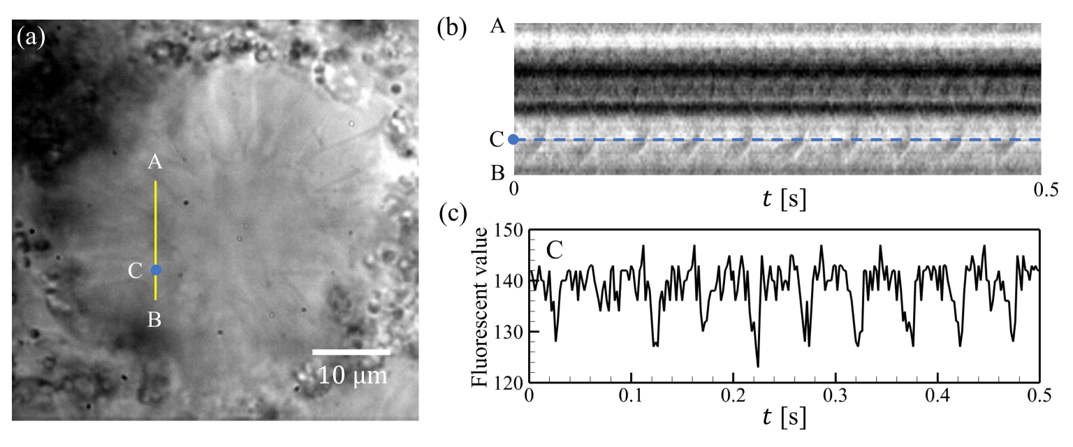
Imaging: Choanocyte chambers of E. muelleri were imaged on an inverted microscope (IX71, Olympus Corp., Tokyo, Japan), as shown in Fig. 2(a). Flagellar beating in the chambers was imaged with a oil immersion objective (100, N.A.= 1.40) and a high speed camera (500 fps, 10241024 pixels, FASTCAM SA3, Photron Limited, Tokyo, Japan) for durations of s. The beating appears as a spatiotemporal brightness fluctuation in the pixels of the images [34, 35], as shown in Fig. 2(b), from which the beat frequency was measured from a fast Fourier transform (n=5, N=3). The various geometric and dynamical characteristics of choanocyte chambers (n=6-8, N=4) and the flagellar motion within them (n=3-5, N=4) are shown in Table 1, in which the results of Spongilla lacustris obtained by Mah et al. [18] are added for comparison.
| Quantity | E. muelleri | S. lacustris111Data for Spongilla lacustris are from Mah et al. [18]. | Simulation |
|---|---|---|---|
| number of flagella | 11231 | 37-359 | |
| flagellar length | 12.91.1 m | 10.40.3 m | 13 m |
| flagellar amplitude | 1.580.21 m | 3.30.9 m | 0.14 |
| beat frequency | 26.18.9 Hz | 11.01.1 Hz | |
| chamber radius | 17.42.5 m | (1.5-3) |
III Computational Fluid Dynamics of choanocyte chambers
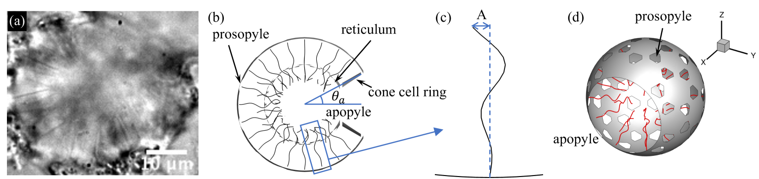
Choanocyte chambers consist of choanocytes arranged in a spherical configuration, each with a single flagellum oriented toward the center of the chamber, propagating bending waves radially inward. In the computations, we represent the chamber as a rigid sphere of radius from which flagella emerge, as in Fig. 3. The chamber has many small inlet holes termed prosopyles and one large outlet hole known as the apopyle. Additionally, there is the gasket-like reticulum, a fine structure that connects the apical part of the collars, which was also observed in Spongilla lacustris [36]. The reticulum delivers high pressure because the choanocyte acts as a collar-vane-flagellum pump system [32]. The reticulum was modeled as a concentric spherical shell inside the choanocyte chamber (Fig. 3(b)), and its radius was varied with the chamber radius so that the length of the collar extending from the choanocyte was a constant m [18]. Finally, cone cells are found in several freshwater sponges including E. muelleri [37], and are flattened near apopyles [36, 38, 37]. They form a ring and connect collars with the walls of excurrent canals to prevent the disadvantageous current. The cone cell ring was modeled as a conical surface near the apopyle (Fig. 3(b)), with an opening angle .
Governing equations: Scaled by the flagellar motion, the Reynolds number in a chamber, so the fluid flow in and around choanocyte chambers is governed by the Stokes equations, and we use slender-body theory [39] for the flagella. Their centerlines are parameterized by arclength , and we measure the chamber radius in units of the flagellar length, with
| (1) |
a parameter that controls the size of the central region of the chamber devoid of flagella. The velocity at point located on flagellum can be written as [40]
| (2) |
where is the viscosity, is the viscous traction on the chamber, is the force density of the flagella and is the total number of flagella. The first integral is over all surfaces , including those of the chamber, reticulum and cone cell ring. The second integral is over flagellar centerlines. In (2), is the Green’s function
| (3) |
where and , and is the kernel [39]
| (4) |
where . Here the radius function satisfies for each , where is the ratio of the length to the radius of flagellum and is set to . The radius function is
| (5) |
When the point is not on a flagellum, the velocity is
| (7) |
Flagellar motions: Each of the flagella within a computational choanocyte chamber is actuated with a prescribed waveform at a frequency , where is the period of motion, and fixed at its base on the choanocyte chamber surface at a point . We define the orthonormal body frame and at as , and , where , and is the outward unit normal vector to the surface. With , the motion of a flagellum is parameterized as
| (8) |
where is the beat amplitude, , with the wavelength, the coordinate spans the time-dependent projected length of the flagellum under the constraint of fixed total arclength . For the oscillating flagellum described by , the projected arclength is considerably less than the total arclength . For the amplitude used in numerics and for the values of typical of experiment we have . This contraction plays an important role in the pressure distribution within the choanocyte chamber. As we observed no phase synchrony in our studies of sponge flagella, much as earlier studies of multicellular choanoflagellates saw no synchrony [42, 43], in computations we randomly set the phase for each flagellum in the range , reproduce the independent flagellar motion in the chamber.
Boundary element method: When the choanocyte chamber is fixed and there is no background flow, the boundary conditions are
| (9) |
where is the flagella velocity, and the chamber includes the reticulum and cone cell ring.
The choanocyte chamber surface, reticulum and cone cell ring were composed of 9,710 triangular mesh elements and 5,401 nodal points. These quantities depended on the chamber radius, the size of apopyles, and the number of flagella. Each flagellum was discretized into 20 elements with 21 nodes. All physical quantities were computed at each discretized point. The boundary integral equations (2)) and (LABEL:eq:v) were computed using Gaussian integration, leading to the linear algebraic equations
| (10) | ||||
| (11) |
Both and have size , and that of and is , where is the total number of nodes on the chamber surface, the reticulum and the cone cell ring, and is the total number of nodes on the flagella. The matrix size of is and is . Considering the boundary condition (9), the equations can be rewritten as
| (12) |
The dense matrix was solved using the lower-upper (LU) factorization technique.
Parameters: To investigate the effects of the choanocyte chamber geometry on the pumping function of the chamber, in the numerical studies reported below we studied a range of several of the parameters of the computational modes: number of flagella , chamber radius (with ), scaled wavenumber , and apopyle opening angle . Through all computations, the calculational time step was set to , where is the flagellar beat period; we also used this in the time averaging method discussed below.
Choanocyte packing fraction: In describing the numerical computations, the various parameters of the setup can be recast in convenient dimensionless quantities. First, if is the opening angle of the apopyle, the area of the chamber available for choanocytes is . We may view the flagellar undulation amplitude in (8) as defining an area associated with each choanocyte, and thus it is natural to define the area fraction of choanocytes on the chamber surface as
| (13) |
For reference, in a hexagonal close packing on a flat surface, the maximum packing fraction is .
IV Numerical Results
IV.1 Basic observations
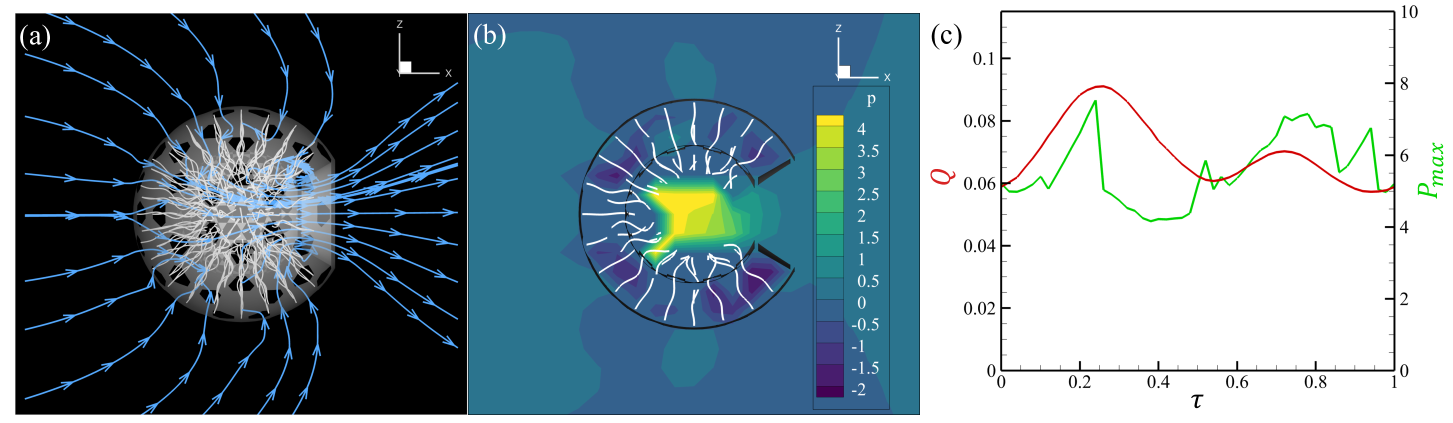
Flow field: The time-averaged flow field and pressure in the center cross-section of a chamber are shown in Figs. 4(a) and (b) for representative parameters. We confirmed that the unidirectional flow, from prosopyle to apopyle, is generated by flagellar beating in the spherical chamber. In this spherical geometry, the pressure field can be divided into low and high pressure regions, as previously reported [36, 32]. The low pressure region sucks water from the prosopyle, while the high pressure region ejects water outward, leading to a unidirectional flow with volumetric rate from the apopyle of
| (14) |
where is the area of the curved surface of the apopyle, is the velocity on , and is the outward unit normal vector on . As the flagellar length is the fixed scale used for nondimensionalizing quantities, we use it and the beat period to define the rescaled flow rate
| (15) |
and its time-averaged value . As shown in Fig. 4(c), does not vary significantly with time. For the parameters , (), and we find , a value that is compared with experimental results in Section 2.
The pressure at point is [44, 45]
| (16) |
where . From the Stokesian balance , with , a suitable rescaled pressure is
| (17) |
which is used to quantify the maximum pressure and its time-average . The time course of is shown in Fig. 4(c), in which the apparent discontinuities arise from abrupt changes in the location of the maxima due to the random flagellar phases.

Flagellar force: The force density and the velocity of node points on a flagellum are shown in Fig. 5(a). These can be used to determine the rate of working of the entire flagellum in moving fluid as
| (18) |
With the force density and speeds scaling as , we define the dimensionless rate as
| (19) |
Intuitively, we see that the magnitude of of each flagellum is largest near the tip, as in Fig. 5(b), which creates high pressure in the center of the chamber.
IV.2 Output increase with number of flagella
To clarify the relationship between the number of flagella in a chamber and its fluid dynamical properties, pumping functions were investigated as the number was varied from to . The pumping function was evaluated according to the outlet flow rate from the apopyles, the rate of working of the flagella, the maximum pressure in the chamber (assuming zero pressure at infinity) and the mechanical pumping efficiency averaged over time during a beat cycle of the flagellar, where
| (20) |
where overbars indicate time-averaged quantities.
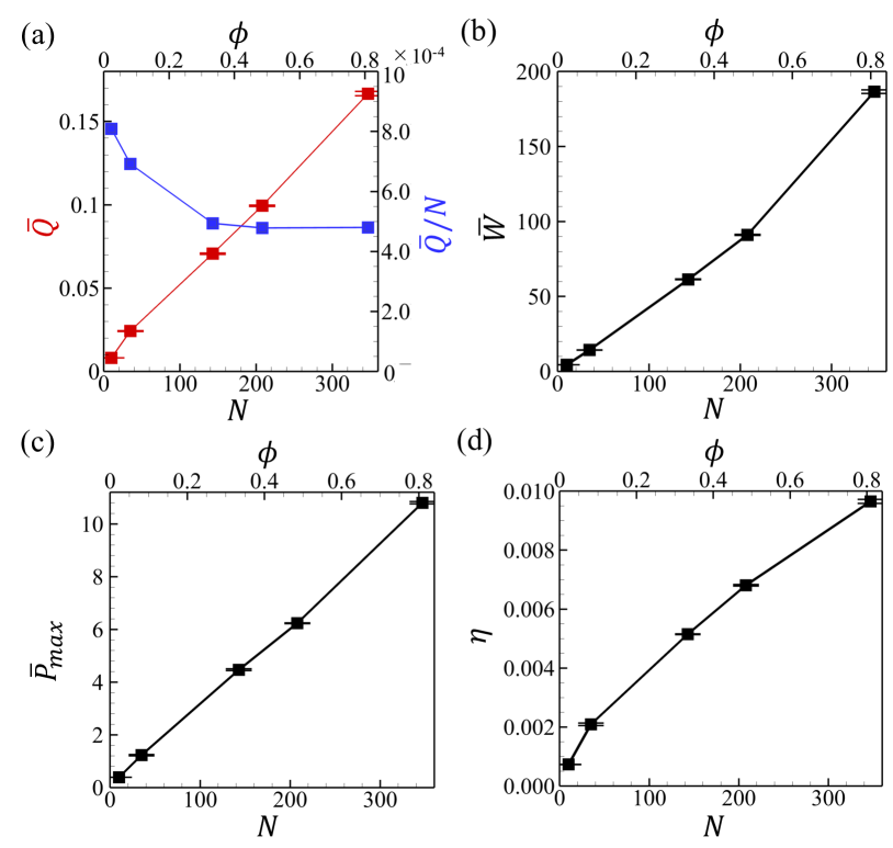

In Fig. 6, ensemble averaged , , , and are shown with three independent phases and rotation angles of the flagellar beating planes. The larger the number of flagella (and the greater the packing fraction ), the greater , , , and , indicating better performance as a pump. Most notably, the average flux is very nearly linear in and the flux per flagellum saturates to a constant value of at large . In interpreting this value it is useful to adopt a simplified view of the flagellum as a localized point force acting on the fluid, a model that has experimental support from studies of Chlamydomonas reinhardtii [46]. The associated Stokeslet flow field, if examined in free space without boundaries, has an infinite flux through any plane orthogonal to the direction of the point force, while for a force orthogonal to a nearby no-slip surface the flux vanishes by fluid conservation. This latter result arises from compensating flows away from the surface near the singularity and toward the surface far away from it. A numerical computation of the flux associated only with the outgoing flows driven by a single model flagellum used in the present calculations, attached to a no-slip wall, gives a value of , a factor of greater than the limit seen in Fig. 6(a). While the porosity of the wall would tend to increase the flux, the tight confinement within the chamber and the typically small apopyle angle clearly leads to significant cancellation. For a given chamber radius, excluded volume effects from cells and their collars limits the number of choanocytes that can be spherically aligned, a limit that depends on the size and shape of the choanocyte. The choanocyte diameter varies among species: m for Tetilla serica [47], m with pseudocylindrical shape for Halisarca dujardini [48], m for E. fluviatilis [49] and m for E. muelleri [50].
IV.3 A smaller chamber radius increases efficiency
We investigated the effect of the chamber radius on the pumping functions such as the efficiency by varying the radius from to while keeping the number density of flagella fixed. As shown in Fig. 7, the flow rate and work rate increased with the chamber radius as the number of flagella also increased. On the other hand, the maximum pressure decreased as the chamber radius increased. The pressure drop was due to the large center space within the chamber, where there are no direct flagella forces. As a result, the mechanical pumping efficiency decreased with increasing radius. These results indicate that a larger chamber has no efficiency advantage, but rather that it is advantageous to pack more choanocytes into a smaller chamber.
IV.4 Efficiency is maximized at intermediate
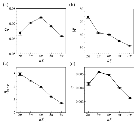
We studied the effect of changing the flagellar wave number while keeping the flagellar length fixed. Interestingly, as shown in Fig. 8, the outlet flow rate and mechanical pumping efficiency exhibit peaks at intermediate values of , while the particular value of the peak differs between the two. The mechanical pumping efficiency reaches a maximum when at the relatively low wave number , where is projected flagellar length. That higher wave numbers lead to reduced efficiency, despite the reduced work rate of the flagella, arises from an effect similar to that found when the chamber radius is reduced; Since is fixed, shrinks at higher wave numbers, increasing the space at the chamber center from which flagella are absent, and the central pressure reduces with higher wave number. The wave number associated with the efficiency is maximized is compared with the experimental results in Section 2.
IV.5 Efficiency is maximized at intermediate
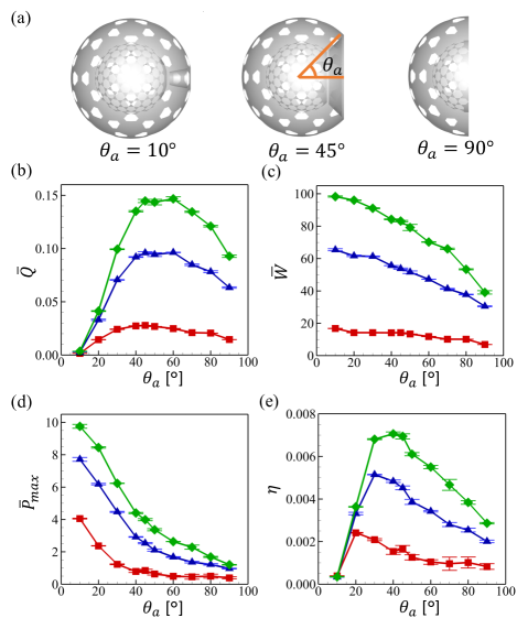
While the choanocyte chamber diameter, apopyle area, and diameter were examined in previous studies [22, 51, 52], it has remained unclear how the apopyle’s aperture ratio affects the pumping function of the chamber. We examined the pumping function while keeping the area fraction within each of three narrow ranges, adjusting the number of flagella with accordingly. Figure 9(b-e) shows the variation in pumping functions with . With all three flagella densities, similar trends were observed, with small variations in the position of various peaks. The outlet flow rates reaches a maximum at . On the other hand, the maximum pressure decreases monotonically with , an effect that arises from the reduction in the the number of flagella directed against the bulk flow as increases. Thus, the spherical shape of the choanocyte chamber has the effect of increasing pressure. Since the pumping efficiency is the product of the maximum pressure and the flow rate, its peak in Fig. 9(e) shifts to the lower regime of compared to the case of the flow rate (cf. Fig. 9(b)). From these results, we conclude that flagella around apopyles, which seem to disturb unidirectional flow, contribute to creating the high pressure rise and that the choanocytes with intermediate but small can achieve high mechanical pumping efficiency.
V Comparison with experiment
|
|
|
(∘) |
|
|||||||||
| 1. Ephydatia muelleri 222, | 34.75.0 | 18.14.3 | 32.26.7 | 11231 | |||||||||
| 2. Haliclona urceolus333Data from Larsen et al. [22]. | 30 | 14 | 27.8 | 80 | |||||||||
| 3. Haliclona permollis444Data from Ludeman et al. [24]. | 30 | 14 | 27.8 | 95 | |||||||||
| 4. Aphrocallistes vastus33footnotemark: 3 | 56 | 26 | 27.7 | 260 | |||||||||
| 5. Neopetrosia problematica33footnotemark: 3 | 23.3 | 16.0 | 43.4 | 80 | |||||||||
| 6. Haliclona mollis33footnotemark: 3 | 28.5 | 14.1 | 29.7 | 139 | |||||||||
| 7. Tethya californiana33footnotemark: 3 | 21.1 | 0.90 | 2.44 | 99 | |||||||||
| 8. Callyspongia vaginalis33footnotemark: 3 | 19.7 | 5.97 | 17.6 | 93 | |||||||||
| 9. Cliona delitrix33footnotemark: 3 | 16.0 | 4.23 | 15.3 | 50 | |||||||||
| 10. Amorphinopsis foetida555Data from Dahihande et al. [30]. | 17.460.13 | 124.11 | 46.1 | 84.113.02 | |||||||||
| 11. Calyspongia sp.44footnotemark: 4 | 19.350.2 | 168.54 | 49.2 | 121.114.33 | |||||||||
| 12. Haliclona sp.44footnotemark: 4 | 19.690.23 | 113.21 | 37.6 | 68.832.82 | |||||||||
| 13. Ircinia fusca44footnotemark: 4 | 30.680.29 | 211.25 | 32.3 | 120.358.98 |
Pumping flow rate: The numerical results in Section IV.1, with parameters taken from experiment, yielded time-averaged flow rates of a choanocyte chamber of . This can be compared with previous experimental results. The flow rate of the choanocyte chamber of Haliclona urceolus was estimated as [22], which is very close to the present results. In addition, the flow rate per choanocyte of a syconoid type sponge was estimated at m3/s [33], and if the flow rate scales with the number of choanocytes, estimated to be (cf. Table 1), we obtain m3/s, also in good agreement with our results. Thus, the flow rate obtained in this study is consistent with former experimental observations.
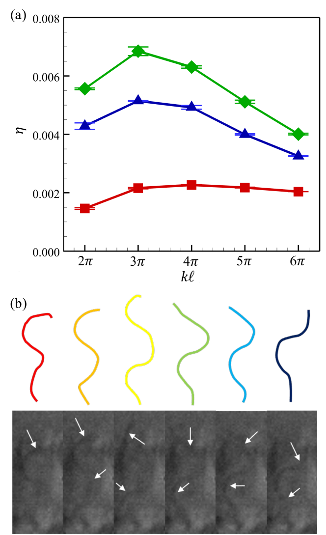
Flagellar wave number: Next, we compare the wave number at which the efficiency is maximized with our experimental results. The mechanical pumping efficiency as a function of the wave number with three different number densities of flagella is shown in Fig. 10(a). We see peaks in efficiency with the , independent of the number density of flagella. In our experiment, the flagellar motion of E. muelleri choanocyte was extracted from the high-speed imaging as shown in Fig. 10(b). From the projected flagellar length m and the wavelength m, we find , in good agreement with the numerical results for the maximum efficiency. Similar trends are seen in other species. In the case of S. lacustris, for example, using m and m [32, 18]. Thus, the flagellar wave number appears to be tuned to maximize the mechanical pumping efficiency.
Chamber size and choanocyte density: Our experimental observations show that the number of flagella in a choanocyte chamber of E. muelleri is , similar to the value found in earlier work on choanocytes of H. urceolus, in which the chamber diameter is m [22]. In several marine sponges, the chamber diameters ranges from m and the number of choanocytes ranges from , which indicates that choanocytes are densely packed in the chamber. There is a positive correlation between the number of choanocytes per chamber and the pumping rate of a sponge according to experimental observations [30]. Hence, it is inferred that the chamber is filled almost completely with as many choanocytes as allowed by the chamber size. These tendencies are consistent with our finding that larger number of flagella enhances pumping function and efficiency.
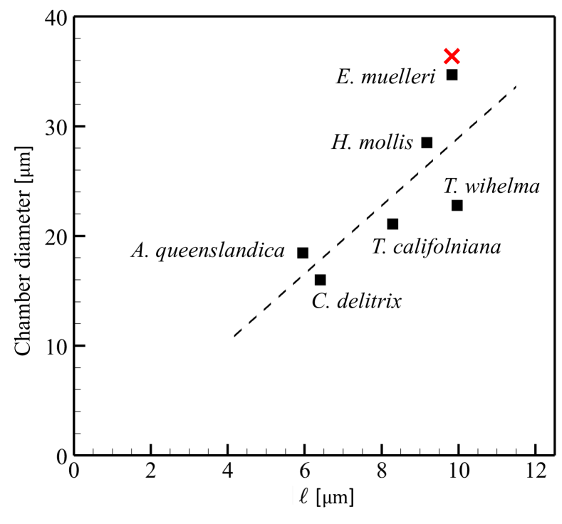
As noted earlier, there is an upper limit on the number density of choanocytes due to the excluded volume of cells and the aperture ratio of apopyles and prosopyles. Hence, to increase the number of choanocytes, the choanocyte chamber is forced to make its radius larger. On the other hand, when the radius is large, the pumping efficiency becomes low. These two conditions are contradictory, so a balance must be reached between them. To find balanced conditions in nature, we plotted the correlation of the flagellar length and the choanocyte chamber diameter for various species of sponge as shown in Fig. 11. We see an obvious positive correlation between them, indicating that the chamber diameter increases with flagellar length. We analytically calculated the hypothetical minimum diameter of E. muelleri under the condition that adjacent flagella of amplitude 3.16 do not contact each other. The result is 36.4 , which is close to the actual diameter of 34.7 . This implies that the chamber diameter is designed to be as small as possible while avoiding overlapping flagella. Smaller chamber diameters may have other advantages, such as the ability to accommodate a larger number of cells in a smaller volume and greater flexibility in the design of the canal in the entire of sponge body.
Outlet opening angle: Finally, we compare the experimentally observed opening angles with the range found to be maximal for pumping efficiency. We observed several cross-sections of a choanocyte chamber of E. muelleri by shifting the focal plane as shown in Fig. 1(c-f). From the image around the apopyle (cf. the top focal plane in Fig. 1(e)), we measure the apopyle diameter. Using this value and the chamber diameter, and assuming a spherical chamber shape, the average apopyle opening angle was found to be be . In the case of E. muelleri, the number density of flagella is , which, with the chamber diameter of , and the flagella number of gives a coverage fraction \colorblue, associated with the blue data in Fig. 9(e) for pumping efficiency, which is maximized at . The very good agreement with the observed value for E. muelleri indicates that the natural configuration of the choanocyte chamber of E. muelleri optimizes the mechanical pumping efficiency.
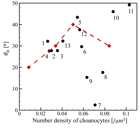
The geometric properties of choanocyte chambers in many sponge species that have been reported previously are collected in Table 2. To compare the present study with these former ones, we plotted the opening angle versus the number density of choanocytes in a chamber. In estimating these values, we assumed the chamber is spherical. Studies on E. muelleri, Haliclona urceolus, Haliclona permollis, Aphocallistes vastus, Neopetrosia problematica, Haliclona mollis, Tethya californiana, Callyspongia vaginalis, and Cliona delitrix [22, 24] explicitly reported information about apopyles, so we could fully incorporate the effect of apopyles when calculating the number density of choanocytes. In studies on Amorphinopsis foetida, Callyspongia sp., Haliclona sp. and Ircinia fusca [30], on the other hand, the apopyle area was not reported and we calculated the number density without taking apopyles into account, thus underestimating the number density. The results are plotted in Fig. 12, in which the present results on those values of that correspond to the maximum mechanical pumping efficiency at various densities are indicated in red. The opening angles of natural sponge choanocyte chambers are clearly close to the computational results for those with maximum efficiency, thus demonstrating that many species of sponge have choanocyte chambers that, like E. muelleri, can achieve high mechanical pumping efficiency.
VI Point Force Model
A recurring theme in biological fluid dynamics is the representation of flow fields around multiflagellated organisms by suitable singularities in Stokes flow. For example, experimental studies of freely-swimming colonies of the green alga Volvox carteri, a spheroid consisting of biflagellated cells on its surface, have shown a dominant far-field behavior associated with a Stokeslet arising from the density offset between the colony and the surrounding water; a single point force accurately summarizes the effects of a thousand cilia [54]. At smaller scales, an accurate representation of the swirling flows near a single biflagellated alga Chlamydomonas reinhardtii when it swims in a breaststroke fashion requires three point forces: one for the cell body and one each for the opposing flagella [54, 55].
Returning to the densely-packing choanocyte chambers, it is natural to examine the extent to which the fluid dynamical properties we have found in the numerical studies described above can be represented by the action of one or several point forces. Such a representation would be useful in understanding the input-output characteristics of the chamber, particularly within a coarse-grained model of the the sponge network.
In the original full simulation, there were flagella, the reticulum and the cone cell ring inside a spherical chamber, and the flow was generated as shown in Fig. 13(a). We then integrated the forces acting on these internal structures consolidated them into a set of point forces. Fig. 13(b-d) shows the flow field when the internal structure is divided almost equally into sections and point forces are applied at the indicated locations, for the cases (b) , (c) and (d) point force at the sphere center. In all of these coarse-grained models, a flow can be observed from the center of the spherical chamber towards the apopyle.
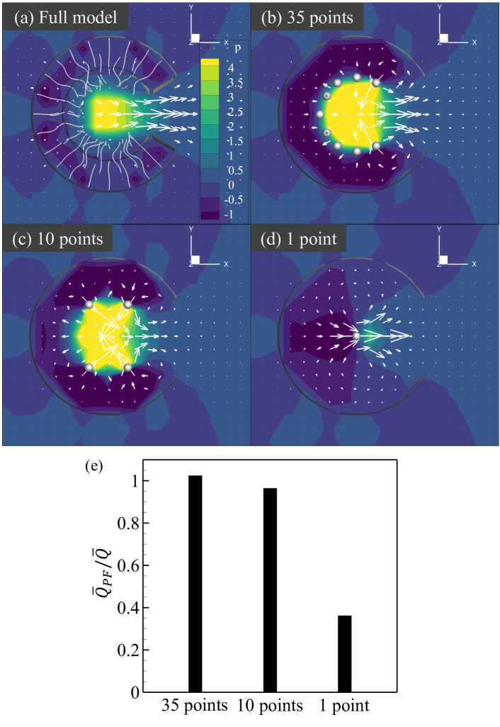
Fig. 13(a-d) also show the pressure field. Due to the different distribution of forces, the pressure distribution is also altered from one value of to another, but for all values there is a similar scale of the high pressure acting at the centre of the chamber. It is only when that there is a significant reduction in the central pressure. This can be seen in the flow rate of the coarse-grained models relative to that in the fully-resolved numerics, shown in Fig. 13(e). Even for as small as flux is quantitatively matched within a few percent. But the single point force drastically underestimates the flux as a direct consequence of underestimating the central pressure. We conclude that the effects of flagella around the apopyle, opposed to the directional flow, are indeed crucial to obtain the scale of flux from choanocyte chambers seen in experiment. At the same time, a significantly simplified representation of the chamber is possible.
VII Conclusions
In this study, we combined direct imaging of choanocyte chambers in living sponges with computational studies of many-flagellum models of their fluid mechanics to unravel the biological significance of the spherical shape of choanocyte chambers. We determined that there are ideal conditions for achieving maximum mechanical pumping efficiency for such a geometry. First, to achieve better efficiency, the chamber radius should be as small as possible and the number density of choanocytes per chamber should be as large as possible. Excluded volume effects limit the range of densities, and we found for E. muelleri and several other species that the chamber diameter is as small as possible while avoiding overlapping flagella. Second, the optimum wave number for mechanical pumping efficiency was found to be when the chamber radius is times the flagellar length. This linkage was in good agreement with experimental results on E. muelleri. Third, the optimum opening angle for mechanical pumping efficiency was found to be in the range , with a value for E. muelleri of , which was again in good agreement with the experimental result of . The computational estimate of the optimum opening angle is also in good agreement with those of many other species.
In addition, our computational analysis revealed that those flagella that beat against the dominant flow play a role in raising the pressure inside the choanocyte chamber. As a result, the mechanical pumping efficiency—calculated from the pressure rise and flow rate—reaches a maximum at a modest outlet opening angle. Given that high pumping efficiency is achieved in many species (cf. Fig. 12), the choanocyte chamber may have evolved to optimize this feature, which can be viewed as a means of overcoming the high fluid dynamical resistance of the complex canal. Finally, out investigation of the fidelity of coarse-grained models of the chamber reveals that such simplifications can be taken too far to be accurate, particularly when much of the phenomena of interest are in the near-field regime, as they appear to be for sponge choanocyte chambers. This result does not preclude appropriate coarse-grained models for networks of chambers, only that the input-output characteristics are nontrivial. Logical next steps include development of such models, and on a more fundamental level understanding the developmental processes that lead to such complex network architecture in leuconoid sponges.
Acknowledgements.
This work was supported by JST SPRING, Grant Number JPMJSP2114, JST PRESTO (Grant Number JPMJPR2142). K.K. was supported by the Japan Society for the Promotion of Science Grant-in-Aid for Scientific Research (21H05303, 21H05306, 22H01394) and JST FOREST Program, Grant Number JPMJFR2024. T.I. was supported by the Japan Society for the Promotion of Science Grant-in-Aid for Scientific Research (JSPS KAKENHI Grant No. 21H04999 and 21H05308). R.E.G. acknowledges support from the Wellcome Trust Investigator Grant 207510/Z/17/Z and The John Templeton Foundation.References
- Brain et al. [2012] C. Brain, A. R. Prave, K.-H. Hoffmann, A. E. Fallick, A. Botha, D. A. Herd, C. Sturrock, I. Young, D. J. Condon, and S. G. Allison, The first animals: ca. 760-million-year-old sponge-like fossils from Namibia, South African Journal of Science 108, 1 (2012).
- Reiswig [1971] H. M. Reiswig, In situ pumping activities of tropical Demospongiae, Marine Biology 9, 38 (1971).
- Kahn et al. [2015] A. S. Kahn, G. Yahel, J. W. F. Chu, V. Tunnicliffe, and S. P. Leys, Benthic grazing and carbon sequestration by deep-water glass sponge reefs, Limnology and Oceanography 60, 78 (2015).
- de Goeij et al. [2008] J. M. de Goeij, H. van den Berg, M. M. van Oostveen, E. H. G. Epping, and F. C. van Duyl, Major bulk dissolved organic carbon (doc) removal by encrusting coral reef cavity sponges, Marine Ecology Progress Series 357, 139 (2008).
- de Goeij et al. [2013] J. M. de Goeij, D. van Oevelen, M. J. A. Vermeij, R. Osinga, J. J. Middelburg, A. F. P. M. de Goeij, and W. Admiraal, Surviving in a marine desert: The sponge loop retains resources within coral reefs, Science 342, 108 (2013).
- Achlatis et al. [2019] M. Achlatis, M. Pernice, K. Green, J. M. de Goeij, P. Guagliardo, M. R. Kilburn, O. Hoegh-Guldberg, and S. Dove, Single-cell visualization indicates direct role of sponge host in uptake of dissolved organic matter, Proceedings of the Royal Society B 286, 20192153 (2019).
- Hammel et al. [2012] J. U. Hammel, M. V. Filatov, J. Herzen, F. Beckmann, J. A. Kaandorp, and M. Nickel, The non-hierarchical, non-uniformly branching topology of a leuconoid sponge aquiferous system revealed by 3d reconstruction and morphometrics using corrosion casting and x-ray microtomography, Acta Zool. 93, 160 (2012).
- Yin et al. [2015] Z. Yin, M. Zhu, E. H. Davidson, D. J. Bottjer, F. Zhao, and P. Tafforeau, Sponge grade body fossil with cellular resolution dating 60 myr before the cambrian, Proc. Natl. Acad. Sci. USA 112, E1453 (2015).
- Ruppert et al. [2004] E. Ruppert, R. Fox, and R. Barnes, Invertebrate Zoology, 7th ed. (Thomson-Brooks/Cole, Belmont, CA, 2004).
- Redmond and McLysaght [2021] A. K. Redmond and A. McLysaght, Evidence for sponges as sister to all other animals from partitioned phylogenomics with mixture models and recoding, Nature Communications 12, 1783 (2021).
- Simion et al. [2017] P. Simion, H. Philippe, D. Baurain, M. Jager, D. J. Richter, A. D. Franco, B. Roure, N. Satoh, Éric Quéinnec, A. Ereskovsky, P. Lapébie, E. Corre, F. Delsuc, N. King, G. Wörheide, and M. Manuel, A large and consistent phylogenomic dataset supports sponges as the sister group to all other animals, Current Biology 27, 958 (2017).
- Telford et al. [2016] M. Telford, L. Moroz, and K. Halanych, A sisterly dispute, Nature 529, 286 (2016).
- Nielsen [2008] C. Nielsen, Six major steps in animal evolution: are we derived sponge larvae?, Evolution & Development 10, 241 (2008).
- Nielsen [2019] C. Nielsen, Early animal evolution: a morphologist’s view, Royal Society Open Science 6, 190638 (2019).
- Laundon et al. [2019] D. Laundon, B. T. Larson, K. McDonald, N. King, and P. Burkhardt, The architecture of cell differentiation in choanoflagellates and sponge choanocytes, PLoS Biology 17(4), e3000226 (2019).
- Pinskey et al. [2022] J. M. Pinskey, A. Lagisetty, L. Gui, N. Phan, E. Reetz, A. Tavakoli, G. Fu, and D. Nicastro, Three-dimensional flagella structures from animals’ closest unicellular relatives, the choanoflagellates, eLife 11, e78133 (2022).
- Carr et al. [2008] M. Carr, B. S. C. Leadbeater, R. Hassan, M. Nelson, and S. L. Baldauf, Molecular phylogeny of choanoflagellates, the sister group to metazoa, Proceedings of the National Academy of Sciences 105(43), 16641 (2008).
- Mah et al. [2014] J. L. Mah, K. K. Chrisensen-Dalsgaard, and S. P. Lays, Choanoflagellate and choanocyte collar-flagellar systems and the assumption of homology, Evolution & Development 16(1), 25 (2014).
- Vogel [1974] S. Vogel, Current-induced flow through the sponge, Halichondria, Biol. Bull. 147, 443 (1974).
- Vogel [1977] S. Vogel, Current-induced flow through living sponges in nature, Proc. Natl. Acad. Sci. USA 74, 2069 (1977).
- Vogel [1978] S. Vogel, Evidence for one-way valves in the water-flow system of sponges, J. Exp. Biol. 76, 137 (1978).
- Larsen and Riisgård [1994] P. S. Larsen and H. U. Riisgård, The sponge pump, Journal of Theoretical Biology 168, 53 (1994).
- Riisgård and Larsen [1995] H. U. Riisgård and P. S. Larsen, Filter-feeding in marine macro-invertebrates: pump characteristics, modelling and energy cost, Biol. Rev. 70, 67 (1995).
- Ludeman et al. [2017] D. A. Ludeman, M. A. Reidenbach, and S. P. Leys, The energetic cost of filtration by demosponges and their behavioural response to ambient currents, Journal of Experimental Biology 220(6), 995 (2017).
- Hammel and Nickel [2014] J. U. Hammel and M. Nickel, A new flow-regulating cell type in the demosponge Tethya wilhelma - functional cellular anatomy of a leuconoid canal system, PLOS One 9, e113153 (2014).
- Goldstein et al. [2019] J. Goldstein, H. U. Riisgård, and P. S. Larsen, Exhalant jet speed of single-osculum explants of the demosponge Halichondria panacea and basic properties of the sponge-pump, J. Exp. Mar. Biol. Ecol. 511, 82 (2019).
- Beavers and Joseph [1967] G. W. Beavers and D. D. Joseph, Boundary conditions at a naturally permeable wall, J. Fluid Mech. 30, 197 (1967).
- Vafai and Kim [1990] K. Vafai and S. J. Kim, Fluid mechanics of the interface region between a porous medium and a fluid layer - an exact solution, Int. J. Heat Fluid Flow 11, 254 (1990).
- Fransson et al. [2004] J. H. M. Fransson, P. Konieczny, and P. H. Alfredsson, Flow around a porous cylinder subject to continuous suction or blowing, J. Fluids Struct. 19, 1031 (2004).
- Dahihande and Thakur [2021] A. S. Dahihande and N. L. Thakur, Differences in the structural components influence the pumping capacity of marine sponges, Frontiers in Marine Science 8, 671362 (2021).
- Larsen and Riisgård [2021] P. S. Larsen and H. U. Riisgård, Pumping rate and size of demosponges—towards an understanding using modeling, Journal of Marine Science and Engineering 9, 1308 (2021).
- Asadzadeh et al. [2019] S. S. Asadzadeh, P. S. Larsen, H. U. Riisgård, and J. H. Walther, Hydrodynamics of the leucon sponge pump, Journal of The Royal Society Interface 16, 20180630 (2019).
- Asadzadeh et al. [2020] S. S. Asadzadeh, T. Kiørboe, P. S. Larsen, S. P. Leys, H. U. Riisgård, and J. H. Walther, Hydrodynamics of sponge pumps and evolution of the sponge body plan, eLife 9, 1 (2020).
- Kikuchi et al. [2017] K. Kikuchi, T. Haga, K. Numayama-Tsuruta, H. Ueno, and T. Ishikawa, Effect of fluid viscosity on the cilia-generated flow on a mouse tracheal lumen, Annals of Biomedical Engineering 45, 1048 (2017).
- Omori et al. [2022] T. Omori, K. Kikuchi, M. Schmitz, M. Pavlovic, C. Chuang, and T. Ishikawa, Rheotaxis and migration of an unsteady microswimmer, Journal of Fluid Mechanics 930, A30 (2022).
- Weissenfels [1992] N. Weissenfels, The filtration apparatus for food collection in freshwater sponges (porifera, spongillidae), Zoomorphology 112, 51 (1992).
- Langenbruch and Weissenfels [1987] P. F. Langenbruch and N. Weissenfels, Canal systems and choanocyte chambers in freshwater sponges (porifera, spongillidae)*, Zoomophology 107, 11 (1987).
- Langenbruch [1983] P. F. Langenbruch, Body structure of marine sponges, Marine Biology 75, 319 (1983).
- Andersson et al. [2021] H. I. Andersson, E. Celledoni, L. Ohm, B. Owren, and B. K. Tapley, An integral model based on slender body theory, with applications to curved rigid fibers, Physics of Fluids 33, 041904 (2021).
- Ito et al. [2019] H. Ito, T. Omori, and T. Ishikawa, Swimming mediated by ciliary beating: Comparison with a squirmer model, Journal of Fluid Mechanics 874, 774 (2019).
- Anna-Karin Tornberg and Shelley [2004] A.-K. Anna-Karin Tornberg and M. Shelley, Simulating the dynamics and interactions of flexible fibers in stokes flows, Journal of Fluid Mechanics 196, 8 (2004).
- Roper et al. [2013] M. Roper, M. J. Dayel, R. E. Pepper, and M. A. Koehl, Cooperatively generated stresslet flows supply fresh fluid to multicellular choanoflagellate colonies, Physical Review Letters 110, 228104 (2013).
- Kirkegaard et al. [2013] J. B. Kirkegaard, A. O. Marron, and R. E. Goldstein, Motility of colonial choanoflagellates and the statistics of aggregate random walkers, Physical Review Letters 116, 138102 (2013).
- Pozrikidis [1992] C. Pozrikidis, Boundary integral and singularity methods for linearized viscous flow (Cambridge University Press, 1992).
- Lac et al. [2007] E. Lac, A. Morel, and D. Barthès-Biesel, Hydrodynamic interaction between two identical capsules in simple shear flow, Journal of Fluid Mechanics 573, 149 (2007).
- Brumley et al. [2014] D. Brumley, K. Wan, M. Polin, and R. Goldstein, Flagellar synchronization through direct hydrodynamic interactions, eLife 3, e02750 (2014).
- Watanabe [1978] Y. Watanabe, Structure and formation of the collar in choanocytes of Tetilla serica (lebwohl), demosponge, Develop., Growth and Differ., 20, 79 (1978).
- Gonobobleva and Maldonado [2009] E. Gonobobleva and M. Maldonado, Choanocyte ultrastructure in Halisarca dujardini (demospongiae, halisarcida), Journal of Morphology 270, 615 (2009).
- Funayama et al. [2005] N. Funayama, M. Nakatsukasa, T. Hayashi, and K. Agata, Isolation of the choanocyte in the fresh water sponge, ephydatia fluviatilisand its lineage marker, ef annexin, Development Growth and Differentiation 47, 201 (2005).
- Nikko et al. [2001] E. Nikko, G. V. de Vyver, and E. Richelle-Maurer, Retinoic acid down-regulates the expression of emh-3 homeobox-containing gene in the freshwater sponge ephydatia muelleri, Mechanisms of Ageing and Development 122, 779 (2001).
- Johnston and Hildemann [1982] I. S. Johnston and W. H. Hildemann, Cellular organization in the marine demosponge Callyspongia diffusa, Marine Biology 67, 1 (1982).
- Leys et al. [2011] S. P. Leys, G. Yahel, M. A. Reidenbach, V. Tunnicliffe, U. Shavit, and H. M. Reiswig, The sponge pump: The role of current induced flow in the design of the sponge body plan, PLoS ONE 6(12), e27787 (2011).
- Sogabe et al. [2016] S. Sogabe, N. Nakanishi, and B. M. Degnan, The ontogeny of choanocyte chambers during metamorphosis in the demosponge amphimedon queenslandica, EvoDevo 7, 6 (2016).
- Drescher et al. [2010] K. Drescher, R. Goldstein, N. Michel, M. Polin, and I. Tuval, Direct measurement of the flow field around swimming microorganisms, Phys. Rev. Lett. 105, 168101 (2010).
- Ishikawa [2024] T. Ishikawa, Fluid dynamics of squirmers and ciliated microorganisms, Annu. Rev. Fluid Mech. 56, 119 (2024).