Two-dimensional Closed-Form Analytical Model of Laterally-Excited Film Bulk Acoustic Wave Resonator Multiferroic Antennas
Abstract
To overcome the physical limitations of electrically small antennas, strain-mediated magnetoelectric antennas have been studied experimentally and theoretically. However, current closed-form analytical models include solely one-dimensional approaches. This paper proposes a two-dimensional closed-form analytical model of a laterally-excited multiferroic antenna. To model thickness-shear vibrations, we propose an extended Mason model to two dimensions. This theory solves unidirectionally-coupled elastodynamics-magnetization dynamics-electrodynamics. Without using the infinitesimal dipole approximation, this model provides a closed-form solution of the radiated electromagnetic field with an explicit dependency of the antenna response on the physical parameters, enabling their optimization. Furthermore, we compare the efficiency-bandwidth product of different multiferroic antennas with Chu’s limit in the Akhiezer regime, which delimits the highest achievable mechanical quality factor for acoustic resonators at GHz frequencies. We show that phonon-phonon coupling of Akhiezer damping is most likely to limit multiferroic antenna radiation, not Chu’s limit. Moreover, judicious choice of materials can enhance the maximum efficiency by more than an order of magnitude.
I Introduction
The increasing demand for short-range sensors for biomedical applications, portable wireless devices for monitoring applications, and long-range sensors for extremely low-frequency communication systems has led the path for antenna miniaturization. However, traditional electrically small resonant antennas suffer from physical limitations such as low efficiency and bandwidth, and the platform effect due to the proximity with the ground plane. These limitations have caused antennas to be the constraining factor on many systems over the past several decades [1, 2, 3].
In recent years, mechanical antennas have been developed based on a mechanically induced radiation mechanism. In this mechanism, static electric charges, electric dipoles, or magnetic dipoles are accelerated through mechanical motion, potentially alleviating the difficulties associated with traditional electrically small antennas [4, 5, 6]. Technologies employ rotating permanent magnets [7], rotating electrets [8], or ferromagnetic-piezoelectric heterostructures [9, 10, 11].
Among these new kinds of antennas, the latter, also referred to as multiferroic antennas, when integrated into film bulk acoustic wave resonator (FBAR), have shown to be of particular interest for GHz frequencies applications [9, 10, 12]. The radiation source is the dynamic magnetization (spin wave) in the ferromagnetic thin film generated through the piezoelectrically induced magnetoelectric effect. Modeling such an antenna implies solving a system of coupled equations that include elastodynamics, magnetization dynamics, and electrodynamics.
Domann and Carman first proposed a one-dimensional closed-form model of strain-powered rod antennas, composed of a single bulk piezoelectric material or a single bulk piezomagnetic material [13]. However, radiation-induced from ferromagnetic materials is not in the scope of such a model where magnetization dynamics is not considered. Moreover, the model cannot be applied to multilayer structures and neglects the additional material required for the excitation of ferromagnetic materials. Later, an analytical study used the classical Mason model to study the radiation by a multilayer piezoelectric-piezomagnetic structure at Very-Low-Frequency [14]. The circuit model is one-dimensional and employed for obtaining the impedance characteristic of the multiferroic antenna. Nevertheless, magnetization dynamics is not included, and the radiation is calculated by combining piezomagnetic and piezoelectric constitutive equations with the dipole approximation. Luong and Wang investigated the dynamic magnetoelastic coupling in multiferroic antennas, where for different classes of magnetic materials, the impact of the applied stress orientation was analyzed for optimal coupling [15]. However, the study neglects elastodynamics, and the magnetization is thus only time-dependent. Furthermore, electrodynamics is also not considered and no quantification of the radiation is proposed.
Later, numerical methods have been proposed to study bulk acoustic wave (BAW) multiferroic antennas. Yao et al. introduced a three-dimensional unconditionally stable finite-difference time-domain (FDTD) algorithm for the study of BAW multiferroic antennas near ferromagnetic resonance (FMR) through the simultaneous solving of the coupled Landau-Lifshitz-Gilbert/Newton’s/Maxwell’s equations system [16]. Ji et al. used a one-dimensional FDTD algorithm to investigate the impact of magnon-phonon coupling on the antenna polarization [17]. However, because the physics phenomena considered intervene at very different size scales, numerical algorithms require a large computational time to solve the fully coupled partial differential equations system. A series of Finite-Element-Methods (FEM) based studies have later been proposed to analyze multiferroic antennas under thickness excitation of the piezoelectric [18, 19, 20, 21]. There are methods using the commercially available software COMSOL where magnetostrictive and piezoelectric effects are analyzed separately with the magnetostrictive and the piezoelectric modules of the software. The radiated electromagnetic (EM) field is then calculated with the dipole approximation. Contrary to FDTD algorithms, these FEM-based studies using COMSOL do not solve the system of governing equations simultaneously and therefore neglect the mutual coupling between the governing equations. In doing so, they do not use the full potential of a 3D solution while still keeping its disadvantages, namely the very lengthy computational time.
We propose here a two-dimensional closed-form analytical model of multiferroic antennas integrated into a laterally excited FBAR (XBAR). The XBAR generates thickness-shear modes, implying mechanical vibrations in both thickness and lateral directions. A Mason model extended to two dimensions is proposed to account for the mechanical wave propagation in both directions. Considering a unidirectional coupling between the governing equations, the knowledge of the mechanical displacement in the ferromagnetic layer enables us to obtain a closed-form analytic solution of the space-time-dependent spin wave. The spin wave is plugged into the vector potential as a source term and allows us to calculate the radiated EM field without infinitesimal dipole approximation. The closed-form solutions explicitly specify the parametric relationships, leading the path for an optimization of these parameters. Finally, the efficiency-bandwidth product of different multiferroic antennas is compared with Chu’s limit in the Akhiezer regime. The Akhiezer regime refers to the phonon-phonon scattering, which sets for an acoustic resonator, the highest mechanical quality factor achievable in the GHz frequencies. We show that with a proper selection of piezoelectric and ferromagnetic materials, multiferroic antennas operating at the Akhiezer limit can approach Chu’s limit.
II Theoretical description of laterally excited multiferroic antennas
II.1 Operating principle of multiferroic antennas
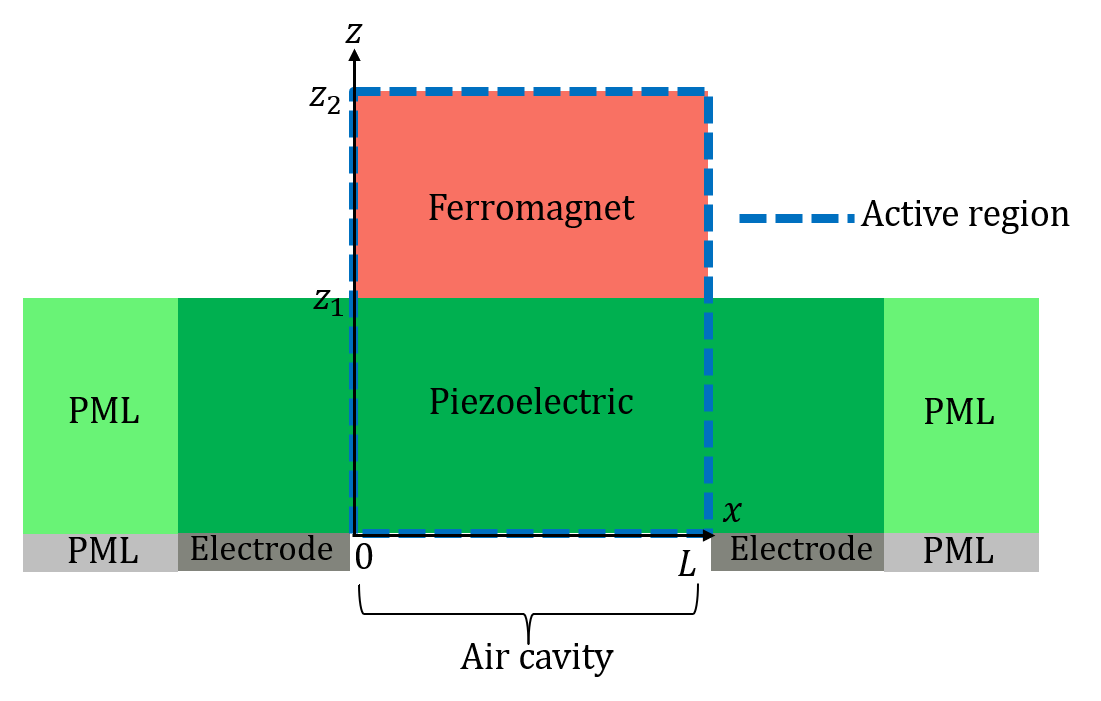
The multiferroic antenna consists of a thin-film piezoelectric material deposited on a silicon substrate with a pair of electrodes placed along the x-axis. On top of the piezoelectric is deposited a thin-film ferromagnetic material. The silicon substrate is etched away to create an air cavity beneath the piezoelectric, enabling vibrations in both lateral and thickness directions. As shown in Fig. 1(a), the active region studied in this analytical model is the free-standing piezoelectric-ferromagnet structure. The active region is delimited by the length of the ferromagnet and the thickness of the antenna. The boundary conditions along the thickness and lateral directions are stress-free conditions. For comparison and verification, the structure is also analyzed using COMSOL, as shown in Fig. 1(a), where both electrodes and piezoelectric material combined with perfectly matched layers (PML) are considered. Aluminum Nitride (AlN), is used as piezoelectric material for its high longitudinal acoustic velocity. Nickel (Ni) is used as ferromagnetic material and Platinum (Pt) for the electrodes. When a time-varying voltage is applied to the electrodes, the piezoelectric is excited and generates acoustic waves in the form of thickness-shear waves. The acoustic waves propagate into the ferromagnetic layer, generating time-harmonic standing spin waves, the source of EM radiation.
The dynamic response of the multiferroic antenna is predicted with a set of equations comprising Maxwell’s equations for EM radiation, the Landau-Lifshitz (LL) equation for magnetization dynamics, and Newton’s Law for acoustic waves:
| (1) |
| (2) |
| (3) |
In (1), are the electric field and the magnetic field, are the electric displacement field and the magnetic flux density, and is the free current. In (2), is the magnetization unit vector defined as , with the magnetization vector, the saturation magnetization. is the effective magnetic field composed of the different physics phenomena that force the magnetization vector to rotate. is the vacuum permeability, is the gyromagnetic ratio with a value of , and is a dimensionless damping constant with a value of [22]. In (3), are the stress and strain fields. is the displacement vector and the density. The superscript refers to the transpose.
Hooke’s law relates the stress and strain fields through the material elastic stiffness tensor and the viscosity tensor . For a non-piezoelectric material:
| (4) |
In the piezoelectric, Hooke’s law takes the form of the so-called piezoelectric constitutive equations:
| (5) |
where is the piezoelectric constant in the stress-charge formulation, and is the piezoelectric permittivity.
The system of equations is solved in a unidirectional way. First, we solve Newton’s law combined with the extended two-dimensional Mason model. Only the Villari effect (inverse magnetostriction) is considered in this work. Thus, the displacement vectors obtained through elastodynamics enable us to find the expression of the magnetoelastic field, the major source of magnetization rotations. Subsequently, the LL equation is solved which gives the spin wave. Finally, the spin wave is plugged into Maxwell’s equations as a source term to obtain the EM far-field.
II.2 Elastic waves
The electrodes placed along the x-axis generate particle displacement on the xz-plane, namely thickness-shear modes. The dominant stress in the structure is the shear stress in the same plane. The shear stress vanishes at the lateral boundaries at and , which leads to the following general form for the x and z components of the displacement vector in the structure:
| (6) |
The propagation constant along the lateral direction x is directly fixed in each layer by the boundary conditions and its value is where . and are the eigenvectors. The piezoelectric and the ferromagnetic materials have different mechanical properties, rendering the bilayer structure inhomogeneous. As a consequence, the wavenumber along the thickness direction varies from one layer to another. It will be denoted as in the piezoelectric and in the ferromagnetic layer. The two propagation constants along the thickness direction cannot be determined merely by the application of boundary conditions. They are determined by the dispersion relations. Inserting and in Newton’s Law and examining individual modes gives the dispersion relations in each layer (See Supplemental Material [23]).
| (7) | |||
| (8) |
In (7) and (8), is the frequency of the AC voltage applied at the electrodes. are the elastic stiffness constants in the ferromagnetic and the piezoelectric layers, respectively, when mechanical damping is considered:
| (9) |
where is the viscosity constant. The dispersion relations relate known quantities, the frequency of the AC applied voltage and the wavenumber in the lateral direction, to the unknown wavenumbers along the thickness direction . Therefore, the latter can be extracted from the dispersion relations. However, the two dispersion relations taken separately cannot uniquely determine the structure’s resonance frequencies. A tool is thus needed to obtain the resonance frequencies of such a multi-layer structure, and this is accomplished by the proposed extended Mason model. In the study of BAW resonators, conventionally, the Mason model has only been employed as a 1D approximation for obtaining the structure’s electrical response: the resonance frequencies through the input impedance or the reflectivity of acoustic mirrors for instance [24]. The 1D analysis is then combined with COMSOL for the study of mode shapes [25]. On the contrary, we show here that extended to two dimensions and combined with Newton’s law, an extended Mason model can give both electrical response and mode shapes.
II.3 Extended Mason model: electrical response
We define an extended Mason model per unit length and extend it to two dimensions taking advantage of the coupling in Newton’s law between the x and z components of the displacement vector. Suppose we project Newton’s equation onto the z-axis and examine the waves propagating along the positive and negative thickness directions. In that case, one can find the coupling relation between the magnitudes along x and z. In the piezolayer for instance (See Supplemental Material [23]):
| (10) |
where is the coupling constant defined by:
| (11) |
In other words, the coupling constant allows a circuit representation of a 2D structure where the wave propagation in one direction is considered first and the wave propagation in the other direction is directly deduced by (10). Fig. 1(b) is the extended Mason model for the present bilayer resonator under lateral field excitation. The left part of the circuit with an electrical port represents the piezolayer, and the right part of the circuit is the ferromagnetic layer. The stress-free boundary conditions at the top and bottom of the active region are represented in the circuit by two acoustic shorts. One at the bottom of the piezolayer, denoted by the plane , and the other at the top of the ferromagnetic layer denoted by the plane . The plane is the piezoelectric-ferromagnet interface. In the circuit, the voltages are the modal shear forces denoted as .

Owing to the orthogonality of the mechanical waves, we modify the definition of the shear force by taking the weighted integral along the x-axis of the shear stress. In the piezolayer:
| (12) |
where is the thickness of the piezolayer, the time-varying voltage applied to the electrodes, and the piezoelectric coupling constant for an electric field applied along the x-axis. Defining the modal shear force as a weighted integral allows two things. First to quantify how much each mode couples with the applied electric field in the lateral direction, represented by the coefficient . Second to account for the coupling between the waves propagating in the thickness and lateral directions in the definition of the mechanical impedance :
| (13) |
In the circuit, the currents are the magnitude of the acoustic velocities along the lateral direction denoted as . Applying Kirchhoff’s laws, we can solve for the magnitudes of the acoustic velocities at the planes and :
| (14) |
where and are the ferromagnetic layer’s thickness and mechanical impedance, respectively. (14) gives the magnitude of the acoustic velocities of the n-th propagating mode at the top and bottom of the piezolayer with respect to the applied voltage . The modal current is the surface integral of the modal displacement field along the thickness and width of the piezolayer [26]:
| (15) |
where is the width of the piezolayer. Note that the modal current is a function. Therefore, we modify the classic Mason model again by taking the modal current’s mean value. It enables to take into account the contribution of the propagation in the lateral direction to the modal current’s magnitude:
| (16) |
The input admittance can be obtained by expressing the total current as a function of the applied voltage . The total current is defined as the sum of the static current, related to the piezoelectric static capacitance, and the current flowing in the motional branches. The latter is the sum over all the modes of the mean current . The input admittance can now be written as:
| (17) |
where is the piezoelectric static capacitance, and is the effective electromechanical coupling coefficient of the n-th mode that can be expressed as:
| (18) |
where . Note here that corresponds to the lateral component and follows from the Berlincourt’s formula [27]:
| (19) |
where is the electric field induced by the applied voltage along the x-axis. The input admittance is now defined. The mechanical quality factor of the XBAR multiferroic antenna can be expressed as [28]:
| (20) |
where can be expressed in terms of the input admittance as:
| (21) |
where is the system impedance.
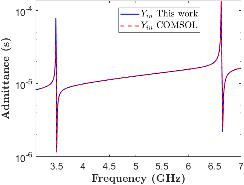
Material properties of AlN and Ni layers, along with the Pt electrodes, are tabulated in Table I. The thickness of the AlN and Ni layers are 400 and 300 nm respectively. The width of the AlN layer is mm and the length of the active region is . In COMSOL, the electrodes’ thickness and length are 30 nm and 200 respectively. The Anchor losses are modeled in COMSOL and this model with a common viscosity constant for the piezoelectric and ferromagnetic materials of . The dielectric losses are also taken into account with a loss tangent of .
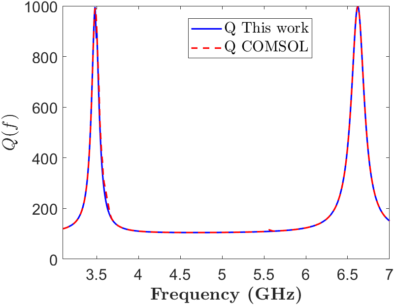
Fig. 1(c) shows the frequency responses of the input admittance obtained with this model and with COMSOL simulation. The first two acoustic resonances are observed at 3.49 GHz and 6.63 GHz. Fig. 1(d) compares the quality factor of the XBAR multiferroic antenna obtained with this model and with COMSOL. At each resonance, the quality factor reaches a value of approximately 1000, corresponding to the inverse of the viscosity constant.
II.4 Extended Mason model: mode shape
We show here that the extended two-dimensional Mason model allows us to describe particle displacement in both the thickness and lateral directions. In the piezolayer, the relation between the displacement magnitude and the acoustic velocities magnitude is (See Supplemental Material [23]):
| (22) |
Recall that (14) defines the acoustic velocities magnitude and that the coupling condition (10) relates the magnitudes in the other direction. Therefore, the particle displacement along the thickness and lateral directions in the piezolayer can be expressed as:
| (23) |
where are constants defined as:
| (24) |
The continuity of the stress is automatically considered in the circuit when Kirchhoff’s laws are applied. As a consequence, only the continuity of the displacement vector at the piezoelectric-ferromagnet interface needs to be verified. Taking into account the stress-free condition at the top surface of the ferromagnetic layer leads to the following displacement vector components in the ferromagnetic layer:
| (25) |
where are constants defined as:
| (26) |
In each layer, the shear stress and strain in the xz-plane are derived using Hooke’s law:
| (27) |
where we considered pure shear stress. In the present study, we considered the active region as a bilayer structure for simplicity. In the case where a structure with more than two layers is considered, the solution procedure of the problem is similar. Adding extra layers of non-magnetic buffer materials will shift the resonance frequencies and similarly to the present case, the continuity of the shear force would be automatically considered in the circuit. The continuity condition on the displacement vector solely needs to be applied to define in each layer the mode shape.
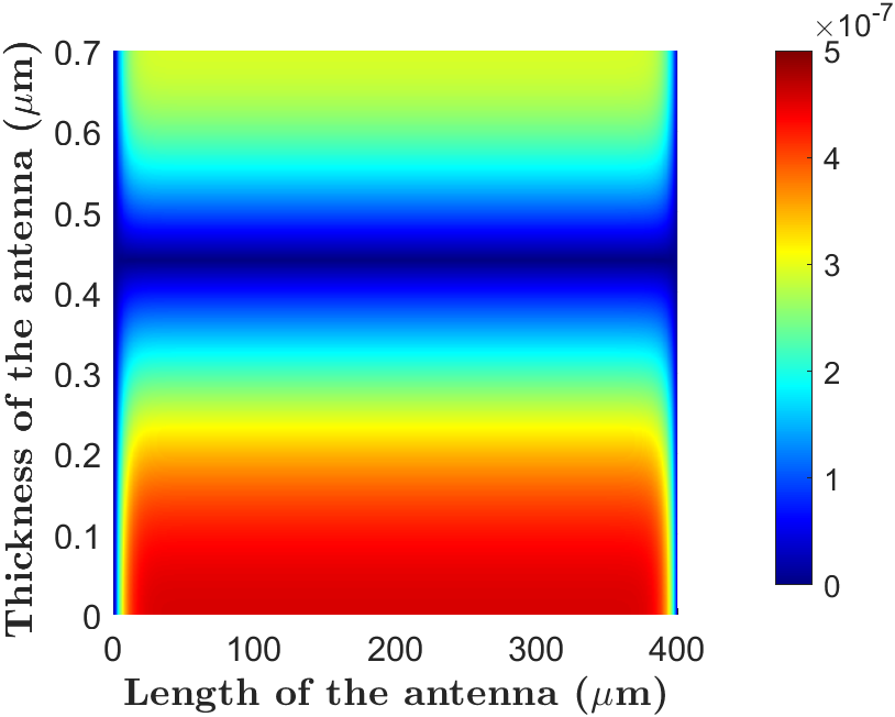
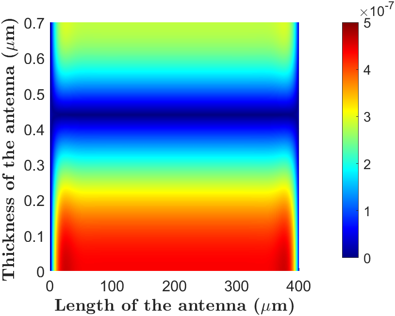
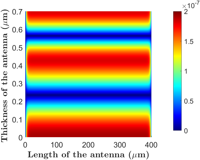
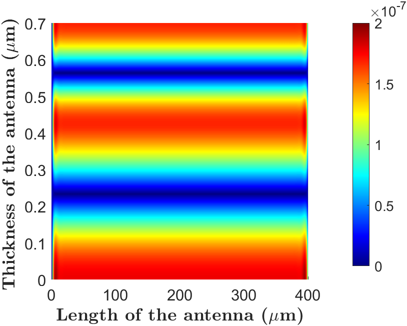
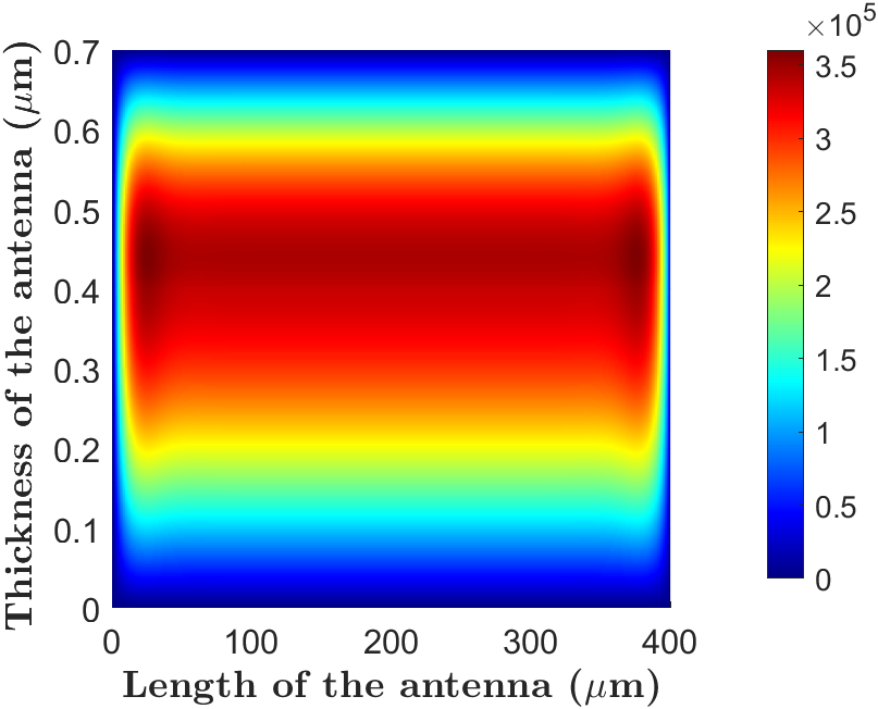
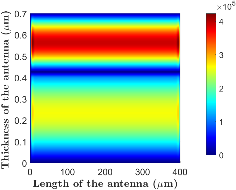
Figs. 2(a)-2(d) plot in the active region, at the first two resonances, the magnitude of the displacement vector obtained with this model and with COMSOL. At the first resonance or 3.49 GHz, we observe zero displacements at . The displacement magnitude starts to increase when leaving the plane . It indicates that the shear force, proportional to the displacement gradient, is higher at this plane. At the second resonance or 6.63 GHz, the displacement gradient is higher in the middle of both layers, indicating that the shear force is maximized in the middle of each layer. This is indeed verified by the plots of the stress magnitudes at the first and second resonances shown in Figs. 2(e)-2(f). The maximum shear stress in the ferromagnetic layer reaches a value of 0.35 MPa for the first resonance and 0.42 MPa for the second resonance. As a consequence, the second mode will generate higher magnetization rotation in the ferromagnet through the magnetoelastic field, leading to higher radiation.
The knowledge of mechanical displacement enables us to define the magnetoelastic field, the principal component of the effective magnetic field that generates the torque that rotates the magnetization. As will be detailed next, the spin wave is calculated analytically for both time and space dependencies with a unidirectional coupling considered.
II.5 Standing spin waves
The LL equation describes the magnetization precession around an effective magnetic field , which can be decomposed into several components:
| (28) |
where is the bias magnetic field oriented along the x-axis in this study. the exchange interaction field, the magnetocrystalline anisotropy field, and the magnetoelastic field.
For thin ferromagnetic films, the demagnetizing field along the thickness direction forces the magnetization to lie in the xy-plane. In the absence of a strong out-of-plane external magnetic field that would cancel the demagnetizing effect, the magnetization unit vector has a weak z component. We will neglect this component and consider the magnetization unit vector to lie entirely in the xy-plane:
| (29) |
where is the angle between and the x-axis. For a cubic crystal, the exchange interaction field, the magnetocrystalline anisotropy field, and the magnetoelastic field are written respectively:
| (30) |
is the exchange stiffness constant, the cubic anisotropy constant and the magnetostriction constant along the crystallographic direction . The projection on the x or y-axis of the LL equation gives the partial differential equation satisfied by the angle :
| (31) | |||||
Acoustically actuated magnetoelectric antennas radiate electromagnetic waves through a perturbation of the magnetization [15]. The magnetization is biased along the x-axis, and the dominant static magnetization is along the x-axis. The magnetization unit vector can therefore be linearized as:
| (32) |
The linearization of the magnetization vector also linearizes the LL equation:
| (33) | |||||
The boundary condition verified by at and is:
| (34) |
where is the vector normal to the xy-plane. Moreover, the ferromagnetic layer thickness is much smaller than the lateral direction , so the boundary condition at the lateral boundaries and can be approximated by a magnetic wall [29]:
| (35) |
The solution of (33) can be decomposed into a time-harmonic term that corresponds to the magnetoelastic contribution and a decay term. The time-harmonic term only plays a role in the radiation and is given by (See Supplemental Material [23]):
| (36) |
where is the magnitude of the stress in the ferromagnetic layer in (27). The spin wave is complex-valued, implying that both magnitude and phase are used to describe it.
| Ni [30] | |
|---|---|
| (A/m) | |
| (mT) | 30 |
| (J/m) | |
| () | |
| (GPa) | |
| () | 8900 |
| 1 | |
| 0.025 | |
| 0.001 | |
| AlN [31] | |
| () | -0.48 |
| (GPa) | |
| () | 3300 |
| 9 | |
| 0.01 | |
| 0.001 | |
| Pt [31] | |
| (S/m) | |
| () | 21450 |
| E (GPa) | 168 |
| 0.38 | |
| 0.001 | |
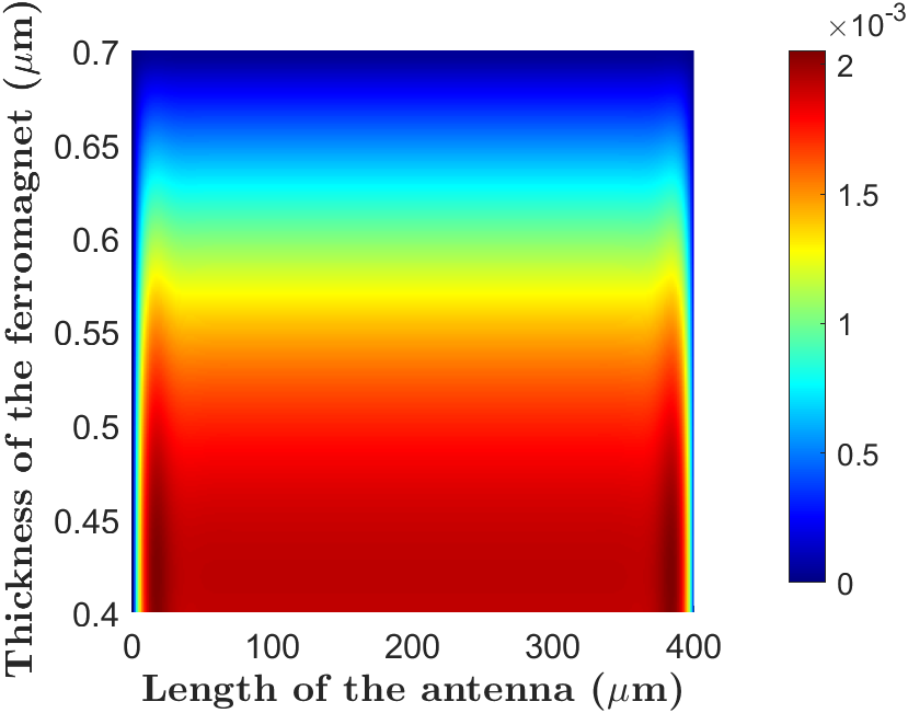
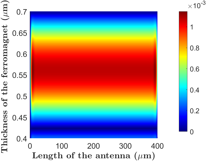
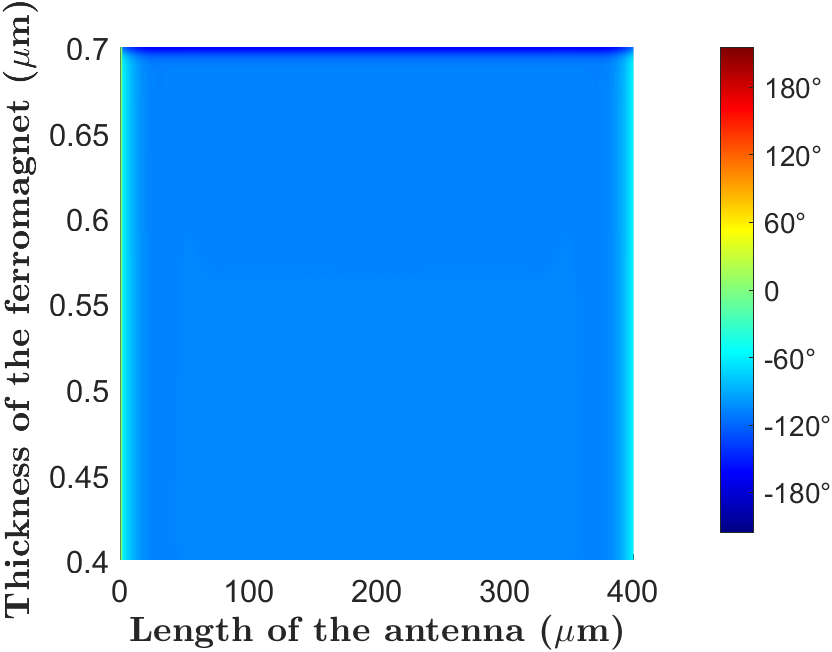
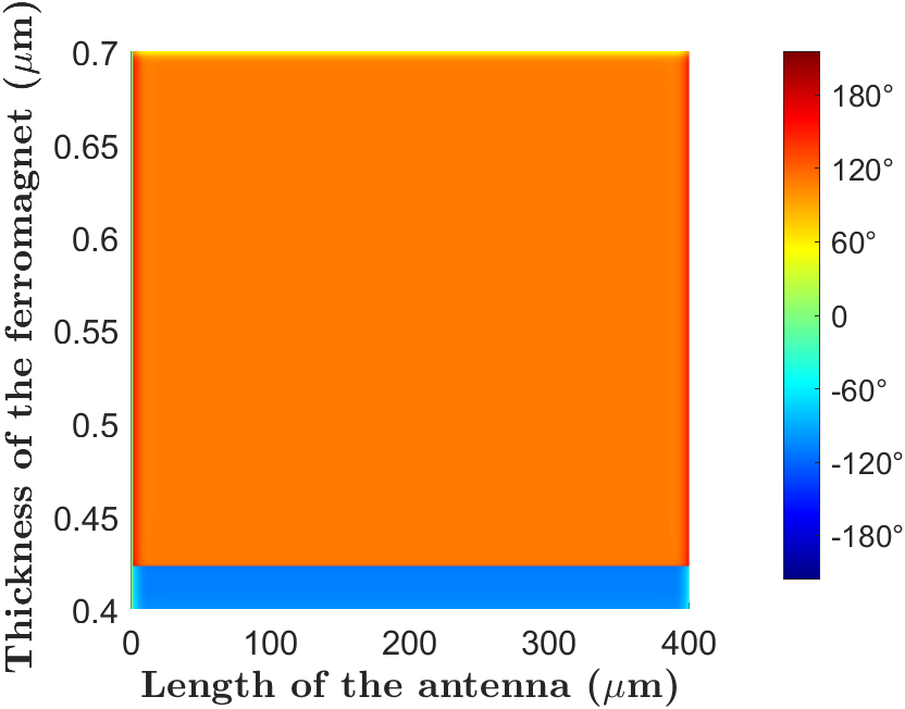
Fig. 3 shows the spatial distribution of the magnitude and phase of the time-harmonic standing spin wave in the ferromagnetic layer at the first and second mechanical resonances. As expected from (33), the spatial distribution is the same as the shear stress. At the first resonance, the magnitude decreases along the thickness of the ferromagnetic layer from at to 0 at the top of the ferromagnetic layer . At the second resonance, the magnitude is constant in the middle of the ferromagnet with a normalized value of . Figs. 3(c)-3(d) show that the spin wave at the second resonance has an opposite phase compared to the first resonance in the upper part of the ferromagnetic layer. It corresponds to the change of polarity after each zero of the displacement vector for a thickness-shear mode.
The spin waves being calculated here for both space and time dependencies, enables as shown further, to obtain an analytical expression of the electric vector potential in the far-field without the use of the infinitesimal dipole approximation. Moreover, since the electric vector potential is a volume integral of the time-derivative of the magnetization, by examining the stress and spin wave spatial distribution, we expect the second mode to radiate more than the first mode.
II.6 Electromagnetic waves radiation
Recalling the definition of the magnetic field , in a ferromagnetic material, a time variation of the magnetization, equivalent to a time variation of the magnetic field, generates an electric field through the Maxwell-Faraday equation. The radiation source is:
| (37) |
where we used the small angle approximation (32). The radiation source is a magnetic current source along y. One obtains the EM field through the computation of the associated electric vector potential in the volume of the ferromagnet. In the far field zone:
| (38) |
where is the width of the ferromagnetic layer, the distance to the observation point, spans the ferromagnet volume and is the free-space wave number. is the angle between the vector that goes from the origin of the coordinate system to the observation point and the vector that goes from the origin to the source point. (See Supplemental Material [23] for the explicit expression of the vector potential). Therefore, it is possible to obtain a closed-form solution of the radiated EM field whose components are expressed by:
| (39) |
where is the vacuum impedance and the unit vectors in spherical coordinates. The radiation power is given by:
| (40) |
The radiation efficiency is calculated by:
| (41) |
where is the accepted power by the multiferroic antenna, expressed in terms of the input admittance , the applied voltage , and the system impedance as [16]:
| (42) |
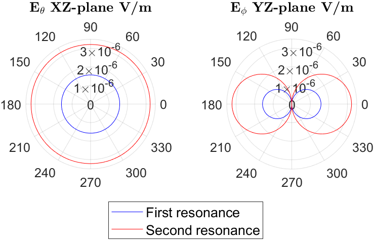
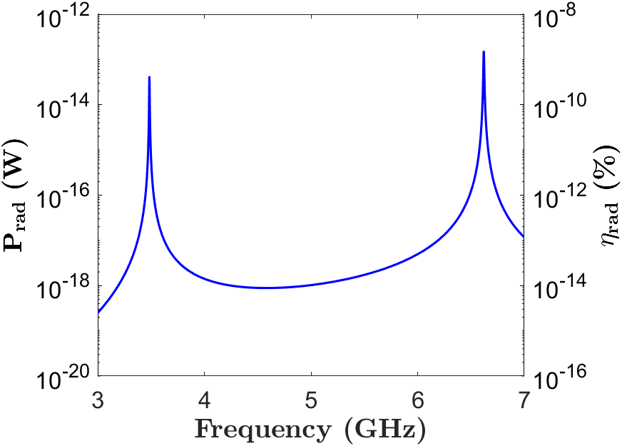
Fig. 4(a) shows the radiated EM field of the multiferroic antenna in the xz-plane and yz-plane for the first two resonances. The planar dimensions of the multiferroic antenna are . The radiated field intensity at the second resonance is approximately two times that of the first resonance. Fig. 4(b) shows the radiated power and radiation efficiency at the two resonances. The radiated power of the first and second resonances are W and 0.16 pW respectively, and the corresponding radiation efficiencies are and . Indeed, the maximum values of the stress in the ferromagnetic layer of 0.35 MPa and 0.42 MPa for the first and second resonances, respectively, already indicated a higher radiation from the second resonance. However, as will be discussed in the subsequent part, the thicknesses of the ferromagnetic and piezoelectric layers were not optimized for maximum radiation power.
III Optimization and Akhiezer limit
| [32] | ||
|---|---|---|
| AlN | 0.91 | |
| 2.37 | ||
| 2.37 |
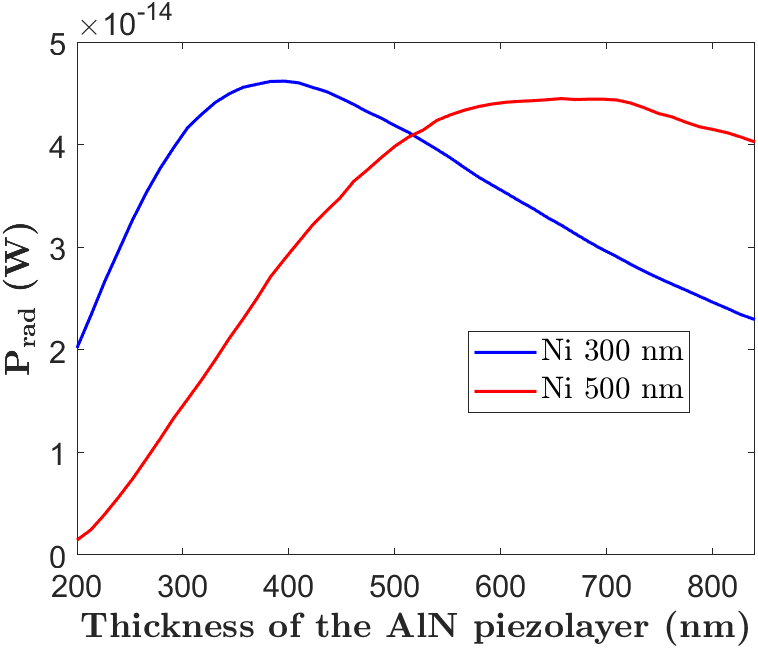
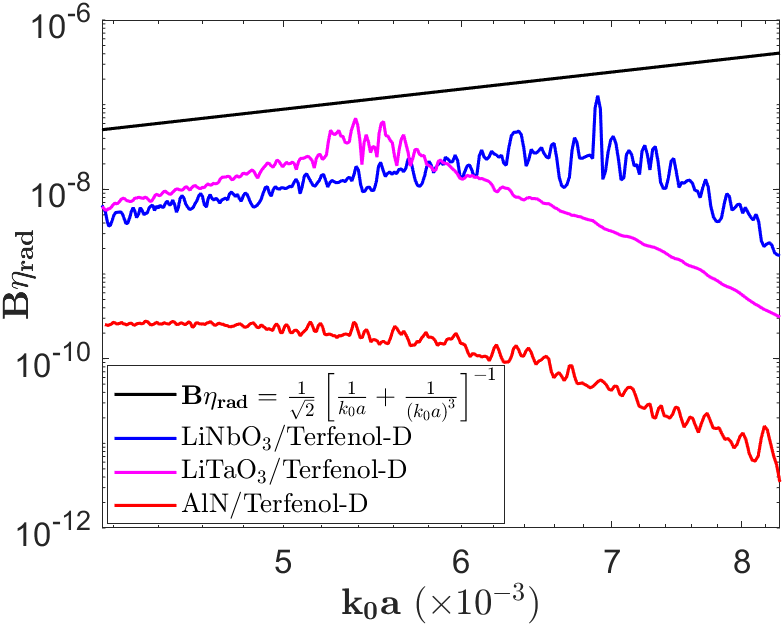
We show in this section the impact of the viscosity constant and the thicknesses of the piezolayer and ferromagnetic layer, on the performance of the multiferroic antenna. Fig. 5(a) plots the radiated power as a function of the thickness of the AlN piezolayer for a thickness of the Ni layer of 300 and 500 nm. For a thickness of the Ni layer of 300 nm, the maximum radiated power is obtained for a thickness of the AlN piezolayer of 380 nm. Moreover, a comparison of the maximum radiated power by the 300 and 500 nm cases, reveals that increasing the thickness of the Ni layer decreases the value of the maximum radiated power from W to W, respectively.
Fig. 5(b) compares the efficiency-bandwidth product of different multiferroic antennas with Chu’s limit. Terfenol-D is used as ferromagnetic material for its giant magnetostriction constant and different piezoelectric materials including AlN, and are compared. The viscosity constant considered is the minimum achievable viscosity constant due to internal frictions, denoted as . Internal frictions are related in the GHz regime to the phonon-phonon scattering, also referred to as Akhiezer damping, which limits the maximum achievable mechanical quality factor for a single crystal-resonator [33, 32, 34]:
| (43) |
where is the mass density, the average Debye acoustic velocity, the average Grüneisen’s parameter, the thermal conductivity, the ambient temperature and the frequency of the AC voltage applied to the electrodes. For simplicity, we consider the of the bilayer structure to be the of the piezolayer. The minimum achievable viscosity constant is calculated taking the inverse of the quality factor . To vary the resonance frequency of the multiferroic antennas, we vary the thickness of the piezolayers from 100 to 1000 nm, with a fixed thickness of the Terfenol-D layer of 500 nm.
At low frequencies, the viscosity constant is low and the bandwidth-efficiency product increases until reaching the maximum value allowed by the structure. Once the maximum value is reached, the bandwidth-efficiency product decreases along with the increase of the resonance frequency, and thus along with the increase of the viscosity constant.
The AlN case has a very low efficiency-bandwidth product because of its low experimental effective electromechanical coupling coefficient :
| (44) |
where and are the series and parallel resonances. and with higher show efficiency-bandwidth products close to Chu’s limit, with values of and at and , respectively. As shown in Fig. 5(b), the choice of or enhances the radiation efficiency by approximately two orders of magnitudes compared to AlN.
IV Conclusions
This paper demonstrates a two-dimensional closed-form analytic model of an XBAR multiferroic antenna. An extended Mason model to two dimensions is proposed to account for the particle displacement along the thickness and the lateral directions. The extended Mason model enables not only to obtain the electrical response of the structure, as the conventional Mason model would do in one dimension, but also allows to obtain the mechanical response through the mode shape. This theory, developed here based on a bilayer piezoelectric-ferromagnet heterostructure, is also applicable to structures with more than two layers. Indeed, adding extra layers of buffer non-magnetic materials only modifies the equivalent impedances seen by the piezoelayer at its top and bottom surfaces, shifting the resonant frequencies. The displacement vector in the ferromagnetic layer, needed for the computation of the electric vector potential, can be obtained similarly as the two-layer case, by application of continuity conditions on the displacement vectors.
Moreover, using a unidirectional coupling between the governing equations, we found closed-form solutions for the spin wave and radiated EM field without the use of infinitesimal dipole approximation. The dependencies between the antenna response and the parameters that compose it are explicitly specified. As a consequence, optimization of these parameters can readily be conducted for the study of radiation enhancement through the definition of the adequate thickness of the piezoelectric and ferromagnet layers leading to the maximum radiated power.
Finally, the efficiency-bandwidth product of different multiferroic antennas is compared with Chu’s limit. The comparison is conducted with the highest achievable mechanical quality factor in the piezolayer, known as the Akhiezer limit. We show that at this fundamental mechanical limit, the efficiency-bandwidth products of /Terfenol-D and /Terfenol-D multiferroic antennas approach Chu’s limit. Furthermore, the choice of Terfenol-D ferromagnetic material combined with or piezoelectric materials allows a radiation efficiency enhancement of approximately two orders of magnitudes compared to AlN/Terfenol-D. Thus, the fundamental factor limiting radiation efficiency is Chu’s limit. However, when considering the coupled physics nature of multiferroic antennas, phonon-phonon scattering in the Akhiezer regime is most likely to limit the antenna radiation for GHz devices, and not Chu’s limit.
Acknowledgments
This work was supported by the National Science and Technology Council, Taiwan, under contracts: NSTC 112-2918-I-002-011, 112-2218-E-002-031, and 112-2119-M-002-015.
References
- Wheeler [1947] H. A. Wheeler, Fundamental limitations of small antennas, in Proceedings of the IRE 35, 1479 (1947).
- Chu [1948] L. J. Chu, Physical limitation on omni-directional antennas, J. Appl. Phys. 19, 1163–1175 (1948).
- McLean [1996] J. S. McLean, A re-examination of the fundamental limits on the radiation of electrically small antennas, IEEE Trans. Antennas. Propag. 44, 672 (1996).
- Hassanien et al. [2020] A. E. Hassanien, M. Breen, M.-H. Li, and S. Gong, A theoretical study of acoustically driven antennas, J. Appl. Phys. 127, 014903 (2020).
- Chen et al. [2020] H. Chen, X. Liang, C. Dong, Y. He, N. Sun, M. Zaeimbashi, Y. He, Y. Gao, P. V. Parimi, H. Lin, and N.-X. Sun, Ultra-compact mechanical antennas, Appl. Phys. Lett. 117, 170501 (2020).
- Schneider et al. [2019] J. D. Schneider et al., Experimental demonstration and operating principles of a multiferroic antenna, J. Appl. Phys. 126, 224104 (2019).
- Glickstein et al. [2020] J. S. Glickstein, S. Choi, A. Madanayake, and S. Mandal, Power-efficient wireless communications using electro-mechanical transmitters, IEEE Access 8, 2455 (2020).
- Cui et al. [2022] Y. Cui, M. Wu, Z. Li, X. Song, C. Wang, H. Yuan, Z.-X. Yang, and J. Zhong, A miniaturized mechanical antenna based on unipolar electrets for extremely low frequency transmission, Microsyst. Nanoeng. 8, 58 (2022).
- Nan et al. [2017] T. Nan et al., Acoustically actuated ultra-compact magnetoelectric antennas, Nat. Commun. 8, 296 (2017).
- Zaeimbashi et al. [2021] M. Zaeimbashi et al., Ultra-compact dual-band smart magnetoelectric antennas for simultaneous wireless energy harvesting and magnetic field sensing, Nat. Commun. 12, 3141 (2021).
- Dong et al. [2020] C. Dong, Y. He, M. Li, C. Tu, Z. Chu, X. Liang, H. Chen, Y. Wei, M. Zaeimbashi, X. Wang, H. Lin, Y. Gao, and N. X. Sun, A portable very low frequency communication system based on acoustically actuated magnetoelectric antennas, IEEE Antennas Wirel. Propag. Lett. 19, 398 (2020).
- Xu et al. [2023] R.-F. Xu, L.-C. Ippet-Letembet, S. Tiwari, Z. Yao, S.-M. Huang, R. N. Chandler, and S.-Y. Chen, Experimental validation of multiferroic antennas in frequency range, Appl. Phys. Lett. 123, 162902 (2023).
- Domann and Carman [2017] J. P. Domann and G. P. Carman, Strain powered antennas, J. Appl. Phys. 121, 044905 (2017).
- Du et al. [2023] Y. Du, Y. Xu, J. Wu, J. Q, Z. Wang, and Z. Hu, Very-low-frequency magnetoelectric antennas for portable underwater communication: Theory and experiment, IEEE Trans. Antennas. Propag. 71, 2167 (2023).
- Luong and Wang [2022] K. Q. T. Luong and Y. E. Wang, Analysis of dynamic magnetoelastic coupling in mechanically driven magnetoelectric antennas, Sensors 22, 455 (2022).
- Yao et al. [2020] Z. Yao, S. Tiwari, T. Lu, J. Rivera, K. Q. T. Luong, R. N. Candler, G. P. Carman, and Y. E. Wang, Modeling of multiple dynamics in the radiation of bulk acoustic wave antennas, IEEE J. Multiscale Multiphys. Comput. Tech. 5, 5 (2020).
- Ji et al. [2022] Y. Ji, C. Zhang, and T. Nan, Magnon-phonon-interaction-induced electromagnetic wave radiation in the strong coupling region, Phys. Rev. Appl. 18, 064050 (2022).
- Cai et al. [2022] X. Cai et al., Finite element analysis and optimization of acoustically-actuated magnetoelectric microantennas, IEEE Trans. Antennas. Propag. 71, 4640 (2022).
- Guokai et al. [2021] X. Guokai, S. Xiao, Y. Li, and B.-Z. Wang, Modeling of electromagnetic radiation-induced from a magnetostrictive/piezoelectric laminated composite, Phys. Lett. A 385, 126959 (2021).
- Li et al. [2022] N. Li, X. Li, B. Xu, B. Zheng, and P. Zhao, Design and optimization of a micron-scale magnetoelectric antenna based on acoustic excitation, Micromachines 13, 1584 (2022).
- Gan et al. [2022] X. Gan, J. Li, J. Li, H. Dong, Z. Gu, and Y. Gao, Kinematic model of bulk acoustic wave antenna considering magnetic damping, J. Magn. Magn. Mater. 563, 170039 (2022).
- Bhagat and Lubitz [1974] S. M. Bhagat and P. Lubitz, Temperature variation of ferromagnetic relaxation in the 3d transition metals, Phys. Rev. B 10, 179 (1974).
- [23] See Supplemental Material at for additional information on the derivation of the dispersion relations, the extended Mason model, the time-harmonic spin wave, and the vector potential., Url.
- Hashimoto [2009] K.-Y. Hashimoto, RF Bulk Acoustic Wave Filters for Communications (Artech, London, 2009).
- Thalhammer and Larson [2016] R. K. Thalhammer and J. D. Larson, Finite-element analysis of bulk-acoustic-wave devices: A review of model setup and applications, IEEE Trans. Ultrason. Ferroelectr. Freq. Control 63, 1624 (2016).
- Rosenbaum [1988] J. F. Rosenbaum, Bulk Acoustic Wave Theory and Devices (Artech, London, 1988).
- Berlincourt et al. [1964] D. A. Berlincourt, D. R. Curran, and H. Jaffe, Piezoelectric and piezomagnetic materials and their function in transducers, Physical Acoustics, Vol. I-A, (W. P. Mason, Academic Press, New York) (1964).
- Jin et al. [2021] R. Jin, Z. Cao, M. Patel, B. Abbott, D. Molinero, and D. Feld, An improved formula for estimating stored energy in a resonator by its measured parameters, in 2021 IEEE International Ultrasonics Symposium (IUS) (2021).
- Demidov and Demokritov [2015] V. E. Demidov and S. O. Demokritov, Magnonic waveguides studied by microfocus light scattering, IEEE Trans. Magn. 51, 1 (2015).
- O’Handley [1999] R. C. O’Handley, Modern Magnetic Material: Principles and Applications (Wiley, New York, 1999).
- [31] COMSOL Multiphysics, http://comsol.com/.
- Ghaffari et al. [2013] S. Ghaffari, S. A. Chandorkar, S.Wang, E. J. Ng, C. H. Ahn, V. Hong, Y. Yang, and T. Kenny, Quantum limit of quality factor in silicon micro and nano mechanical resonators, Nat. Sci. Rep. 3, 3244 (2013).
- Akhiezer [1939] A. Akhiezer, On the absorption of sound in solids, J. Phys. USSR 1, 187 (1939).
- Iyer and Candler [2016] S. S. Iyer and R. N. Candler, Mode- and direction-dependent mechanical energy dissipation in single-crystal resonators due to anharmonic phonon-phonon scattering, Phys. Rev. Appl. 5, 034002 (2016).
- Auld [1990] B. A. Auld, Acoustic Fields and Waves in Solids (Wiley, New York, 1990).
- Polyanin and Nazaikinskii [2016] A. D. Polyanin and V. E. Nazaikinskii, Handbook of Linear Partial Differential Equations for Engineers and Scientists (2nd ed.) (Chapman and Hall/CRC, New York, 2016).
- Polyanin and Zaitsev [2012] A. D. Polyanin and V. F. Zaitsev, Handbook of Nonlinear Partial Differential Equations (2nd ed.) (Chapman and Hall/CRC, New York, 2012).