Light storage in wavy dielectric grating with Kerr nonlinearity
Abstract
Periodical corrugation in dielectric slab transfers the two waveguide modes at zero Bloch wave number into a leaky resonant mode and a symmetry protected bound states in the continuum (BIC) with small frequency detune. The leaky resonant mode can be directly excited by weak linearly polarized normally incident optical field. In the presence of Kerr nonlinearity, the BIC can be indirectly excited by an optical bistable response. Two types of bistable operations are considered. For the first type, the intensity of the incident field gradually increases to exceed a critical value, and then decreases to zero. For the second type, the intensity is fixed, while the linear polarization angle of the incident field gradually increases to exceed a critical value, and then decreases to 0o. Theoretically, the indirectly excited BIC can store the optical energy without loss, even though the intensity of the incident field decreases to zero. Incidence of an optical field with double frequency or orthogonal linear polarization can erase the stored optical field by destroying the BIC. The proposed optical system could function as optical storage and switching device.
pacs:
00.00.00, 00.00.00, 00.00.00, 00.00.00I Introduction
Kerr optical materials have third order nonlinear optical effect, whose reflective index is a linear function of the intensity of the optical field KerrMat1 ; KerrMat2 . As the power of incident optical field change, the optical response of photonic structures consisted of Kerr materials also changes due to the changing of the relative permittivity. The Kerr effect of bulk is weak, because the third order susceptibility is small. Photonic structures, such as photonic crystal pc1 ; pc2 ; pc3 ; pc4 ; pc5 ; pc6 ; pc7 ; pc8 ; pc9 , dielectric grating fengwu19 ; fengwu21 , metallic thin film FZhou10 ; DavidSmith15 , semiconductor thin film semi1 ; semi2 ; semi3 ; semi4 ; semi5 , and graphene Christensen15 , can enhance local density of states of the optical field, which in turn enhance the Kerr effect. One of the most extensively studied Kerr effect is optical bistability bist1 ; bist2 ; bist3 ; bist4 ; bist5 ; bist6 ; bist7 ; bist8 . For a given incident power, the bistable optical devices could have two bistable states with different optical response. The optical devices can be switches between two bistable states as the incident power increases or decreases across a critical value pc8 ; semi2 ; semi3 ; Christensen15 ; switch1 ; switch2 ; switch3 ; switch4 ; switch5 ; switch6 . The two bistable states can be considered as ON and OFF states for all-optical switching devices in integrated photonic.
The mechanism of optical bistability in photonic structures is based on excitation of optical resonant mode with Lorentz line-shape FZhou10 ; DavidSmith15 , whose peak wavelength is approximately a linear function of the refractive index of the Kerr materials. The refractive index of the Kerr materials is a linear function of the intensity of the local optical field (i.e., ), so that the peak wavelength is a linear function of . For a given power of the incident field, is proportional to the incident power and the Lorentz function at the incident wavelength. Because the Lorentz function is inversely proportional to a quadratic function of the difference between the peak wavelength and the incident wavelength, the self-consistent condition gives a cubic function of . If the value of the incident wavelength minus the peak wavelength is a decreasing function of , the local optical field pulls the peak wavelength toward the incident wavelength,so that the cubic function could have three non-degenerated solutions. Two of the three solutions are stable states. The bistable solutions exist if the difference between the incident wavelength and the peak frequency with is larger than a critical value, and the incident power is between two critical values. In other words, when the incident power is smaller (larger) than the lower (higher) critical value, has only one branch of solutions, which is connected with the lower (higher) branch of the bistable solutions. As the incident power increases (decreases) across the higher (lower) critical value, is switched from the lower (higher) branch to the higher (lower) branch. The optical response, such as reflectance and transmittance, is proportional to . The optical resonant mode can be leaky resonant mode FZhou10 or quasi-BIC qbic1 .
In this paper, we consider the situation that a leaky resonant mode is nearly degenerated with a symmetry-protected BIC, which occurs in the wavy dielectric grating maluo22 with small corrugation under normal incident plane wave. The incident frequency is smaller than the resonant frequency of the BIC, and the resonant frequency of the BIC is smaller than the peak frequency of the leaky resonant mode. At low incident power, only leaky resonant mode are excited, and the BIC cannot be excited by the incident plane wave due to symmetry mismatch. As the incident power increases across the higher critical value, the solution of is switched into the higher branch. In this case, the BIC can be excited by the scattered field due to the modification of the spatial distribution of the refractive index. As the incident power subsequently decreases across the lower critical value, the energy in the leaky resonant mode is released, but the energy in the BIC remains being stored. As the incident power further decreases, the energy is still stored in the BIC without loss, because the BIC is not coupled with the radiative mode. Thus, the local optical field does not decreases, and the refractive index remain being modified. As the incident power reaches zero, the self-consistent solution of the BIC of the system with the modified refractive index is still lossless. In order to release the stored energy in the BIC, incident of optical field with different frequency or polarization is applied to destroy the symmetry matching between the modified refractive index and the BIC. This bistable procedure can be applied as light storage devices.
Another type of bistable procedure with fixed incident power is considered, which is driven by tuning the linear polarization angle. In the previous case, both of the leaky resonant mode and the BIC are TE-polarized. At the same incident frequency, the TM-polarized wave is far away from any resonant mode. Thus, incident of TM-polarized plane wave induces weak local optical field. If the linearly polarized angle of the incident plane wave is between TE- and TM-polarization, only the TE component can excite large local optical field and induce sizable Kerr effect. Thus, the effective incident power is given by the power of the TE component of the incident field. As a result, tuning the linearly polarized angle is equivalent to tuning the effective incident power. The effective incident power is smaller than the incident power, so that, in order to switch to the higher branch of the bistable solution, the incident power need to be larger than the higher critical value. After exceeding the higher critical value, the BIC is excited. When the linearly polarized angle is further tuned, if the effective incident power remain being nonzero, the modification of the refractive index is maintained, so that the energy remains being stored in the BIC. As the linearly polarized angle is exactly equal to the TM-polarization, the effective incident power is zero. In this case, the TM-polarized incident field induces the spatial distribution of refractive index that destroys the symmetry matching between the modified refractive index and the BIC, which in turn releases the stored energy in the BIC.
The article is organized as follows: In Sec. II, the linear response of the wavy dielectric grating is discussed. In Sec. III, the bistable procedure by tuning the incident power is discussed. In Sec. IV, the bistable procedure by tuning the linearly polarized angle is discussed. In Sec. V, the conclusion is given.
II Leaky resonant mode and symmetry protected BIC of wavy dielectric grating
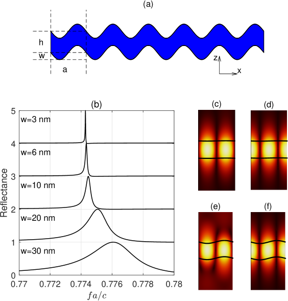
The structure of the wavy dielectric grating is exhibited in Fig. 1(a). A dielectric slab with thickness being is periodically corrugated, with the period being . The top and bottom surfaces are defined by the function , with being the amplitude of the corrugation. A linearly-polarized plane wave is normally incident to the wavy dielectric grating. We consider the TE polarization, with the electric field being along the direction. For a specific example of the numerical simulation, the parameters are assumed to be nm, nm, and being between nm and nm. The background medium is air. The relative permittivity of the dielectric medium with Kerr nonlinearity is assumed to be , with m2/V2, and being the magnitude of the electric field KerrMat1 ; KerrMat2 . The incident power, designated as , is proportional to the intensity of the incident electric field, which is given as . The electromagnetic field is numerically calculated by solving the two-dimensional Helmholtz equation of the y-component electric field, which is given as
| (1) |
where , , is the frequency of the incident field and is speed of light.The spectral element method (SEM) SEM1 ; SEM2 ; SEM3 ; SEM4 ; SEM5 ; SEM6 is applied, which can obtain the solution with high accuracy and efficiency. The computational domain is selected as a rectangular region of one period. Periodic boundary conditions are applied for the left and right boundaries. The top and bottom boundaries are truncated by perfectly matched layer (PML). The total field-scattered field formula is applied to simulated the incident plane wave. The self-consistent solution is obtained by iteratively calculating and .
When is small, the nonlinear term in can be neglected. Thus, we firstly discuss the linear response of the wavy dielectric grating without Kerr nonlinearity. The flat dielectric slab with host waveguide modes, whose dispersion relations are under the light cone. When a periodic boundary condition is imposed into the system, the dispersion relations are folded into the first Brillioun zone, which form a band structure. Band crossings occur at the point of the first Brillioun zone, where the Bloch wave number is zero. The modes at the point are two-fold degenerated. Although the modes at the point are above the light cone, they are non-radiative, because they are waveguide mode. When the periodical perturbation appear, i.e., , the degeneracy of each pair of modes at the point are broken. One of the mode is coupled with the radiative traveling wave, so that the mode becomes leaky resonant mode. The another mode is symmetry-mismatched with the radiative traveling wave, so that the mode is not coupled with any radiative traveling wave. The later mode is the symmetry-protected BIC. The resonant frequencies of the two modes are slightly different. Under normal incident of TE wave with small intensity, the reflectance spectrum has a resonant peak around the resonant frequency of the leaky resonant mode. As decreases, the full-width half-maximum (FWHM) of the peak becomes smaller, as shown in Fig. 1(b). Thus, the Q factor of the leaky resonant mode is inversely proportional to . At the resonant frequency, the magnitude of the electric field within the dielectric medium is enhanced, due to the excitation of the leaky resonant mode. The enhancement factor is also inversely proportional to .
In the absence of the incident field, the resonant modes can be calculated by solving the eigenvalue problem of Eq. 1. The leaky resonant modes and the BICs of the system with nm and nm are calculated. The corresponding field pattern are plotted in Fig. 1(c-f) with the resonant frequencies and the Q factors being given in the caption. As increases from nm to nm, the Q factor of the leaky resonant mode decrease from to . The field patterns of the leaky resonant modes and the BICs have nodal line along direction at () and (), respectively, where is zero. For the leaky resonant modes, the points with maximum value of locate at () where , as shown in Fig. 1(c,e), so that the adjacent points have staggered coordinates. This feature induces scattering by the boundary of the wavy dielectric slab, so that the Q factors are finite. For the BICs, the points with maximum value of locate at () where , as shown in Fig. 1(d,f), so that the points have the same coordinates. The energy only flux along direction, but does not flux along the direction, so that the energy loss is absent.
III Bistability by tuning incident power
In this section, we study the bistability of the optical respond, when is adiabatically increased and then decreased. The first step of the simulation starts with a frequency domain calculation with ultra-low , designated as , so that the Kerr nonlinearity can be neglected. The subsequence steps of the simulation are the frequency domain calculations with being increased with a small value in each step. In each step, the initial value of the electromagnetic field is the convergent solution of the previous step, and the solution is self-consistently obtained by numerical iteration. After steps, reaches a maximum value . For the another subsequence steps, is decreased by in each step. After the simulation of the steps, is back to the initial value .
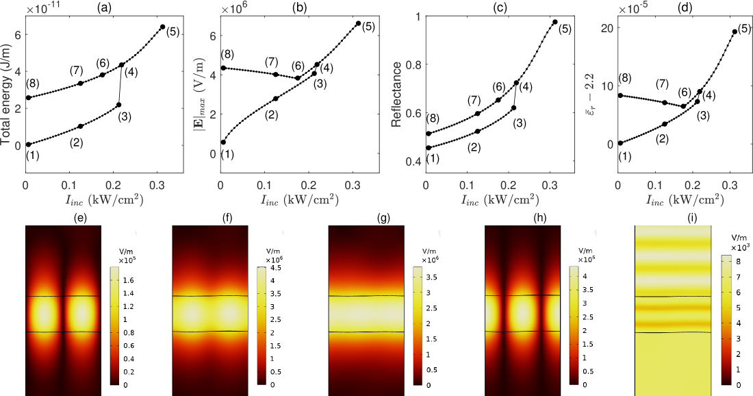
When exceeds a certain critical value, the evolution enter a hysteresis loop. One example with nm is plotted in Fig. 2. The frequency of the incident plane wave is , and the corresponding linear reflectance is , which is at the climbing slope of the resonant peak in Fig. 1(b). The critical value of is kW/cm2. The optical field is characterized by the total energy of the whole computation domain, the maximum value of the amplitude of the electric field (designated as ), the reflectance, and the spatially averaged value of the relative permittivity within the dielectric slab (designated as ), which are plotted in Fig. 2(a), (b), (c), and (d), respectively. Eight typical steps are marked in the evolution curve with indices in sequence.
At the initial step [step (1)], the incident plane wave excites the leaky resonant mode, as shown in Fig. 2(e). Because is equal to kW/cm2 in the initial step, the amplitude of the electric field of the incident plane wave is V/m. The incident plane wave excite the leaky resonant mode with sizably high Q factor, so that the resonant optical field in the wavy dielectric slab is enhanced for times, as shown in Fig. 2(e). The field pattern is superposition of the incident plane wave and the excited leaky resonant mode with large amplitude, so that the field pattern is nearly the same as that of the leaky resonant mode in Fig. 1(c). At step (2) and (3), the field pattern is the same as that in Fig. 2(e), except that the amplitude is larger.
At step (4), exceeds the critical value, and the field pattern sharply changes, as shown in Fig. 2(f). The nodal lines at () are filled with sizable optical field, which imply that the field pattern is superposition of the incident plane wave, the leaky resonant mode and the BIC. Thus, the BIC is excited due to the spatial modification of . The sharp change of the field pattern can be characterized by the shape change of total energy, , the reflectance and . When further increase and reaches step (5), the optical field at () nearly remains the same, and that at () increases. Meanwhile, total energy, , and are nearly proportional to . These phenomenons imply that the stored energy in the BIC remains the same, and the stored energy in the leaky resonant mode is proportional to . As decreases to be smaller than the critical value, the field pattern does not sharply change back to that of step (3), but remain being similar to that of step (4), because the stored energy in the BIC locks the spatial pattern of .
As reaches step (6), the field pattern become nearly uniform along direction, as shown in Fig. 2(g), which implies that the amplitude of the leaky resonant mode and that of the BIC are nearly the same. As further decrease and reaches steps (7) and (8), the store energy in the BIC is larger than that in the leaky resonant mode, so that the total energy continue to decrease, while and hardly change. At step (8), the energy in the leaky resonant mode is much smaller than that in the BIC, so that the field pattern is nearly the same as that of the BIC in Fig. 1(d), as shown in Fig. 2(h). If is tuned down to be zero, the two-dimensional Helmholtz equation become a nonlinear eigenvalue equation. With the spatial distribution of and in step (8) as initial condition, the self-consistent solution of the nonlinear eigenvalue equation give a resonant mode, whose field pattern is nearly the same as that in Fig. 2(h), and Q factor is infinitely large. This resonant mode is the modified BIC of the wavy dielectric grating with nonuniform . To this stage, the optical energy is theoretically stored in the BIC without loss. Applying the same incident plane wave by increasing can only drive the system back to step (8-5), but cannot back to the initial state in step (1).
For applications of optical storage devices, in addition to storing the optical energy, the ability to release the stored energy is also required. In order to release the stored energy, the spatial pattern of has to be changed, which break the symmetry of the modified BIC. This objective can be reached by incidence of plane wave with different frequency. With the field pattern in step (8) as initial condition, iterative solution of the optical field under incidence of plane wave with frequency being double is plotted in Fig. 2(i). The field pattern within the dielectric slab is nearly uniform. With the field pattern in Fig. 2(i) as initial condition, iterative solution of the optical field under incidence of plane wave with the original frequency and is the same as that of step (1). Thus, the stored energy in the BIC is released.
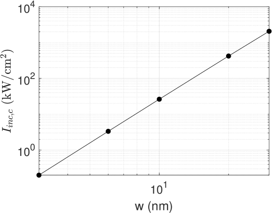
The critical value of between steps (3) and (4), designated as , is dependent on . For the system with larger , the Q factor of the leaky resonant mode is smaller, and then the enhancement of optical field within the wavy dielectric grating is weaker. As a result, larger is needed to induce sufficient modification of . For the systems with varying , are plotted in Fig. 3. By fitting the data, we found that is quartic polynomial function of as .
IV Bistability by tuning linearly polarized angle
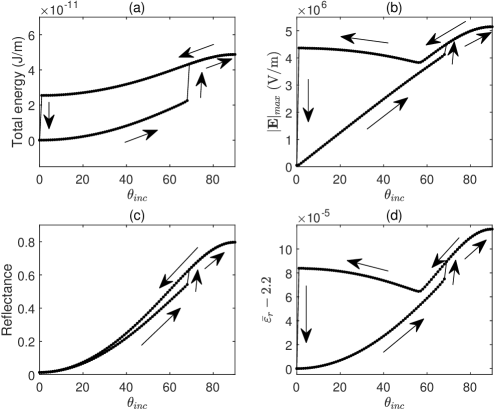
The hysteresis loop can also be driven by variation of linearly polarized angle that is designated as , while keeping the incident power of the normally incident plane wave unchanged. The mechanism of the bistable operation is the same as that in Fig. 2, except that the incident power is replace by effective incident power. The frequencies of the resonant modes of the TE and TM polarization are generally different. When the frequency of the incident plane wave is chosen to be at the middle of the climbing slope of the TE-polarized resonant peak in Fig. 1(b), the frequency is far away from any TM-polarized resonant peak. Thus, at the same frequency, the TM-polarized incident plane wave with incident power being does not induce sufficient modification of for nonlinear response. The electric field of the incident plane wave can be designated as , so that and are corresponding to the TM- and TE-polarized incident plane wave, respectively. For the system with the same parameters as those in Fig. 2 and kW/cm2, the evolution of the characteristic parameters versus are plotted in Fig. 4. The effective incident power for each can be defined as the incident power of the TE-component of the incident plane wave, i.e., . The critical angle that the optical field pattern sharply changes is , at which kW/cm2. The critical value of is slightly larger than the critical value of in Fig. 2, because the modification of by the TM-component of the optical field suppresses the excitation of the BIC. After exceeding the critical angle, the evolution of the bistable state is similar to that in Fig. 2(a-d). As reaches zero, the field pattern sharply change to be the same as the initial state, because the incident TM-polarized plane wave releases the stored energy in the modified BIC. As a result, a complete hysteresis loop is obtained by tuning only without changing the frequency and incident power.
V Conclusion
In conclusion, the bistable processes of optical field in wavy dielectric grating consisted of material with Kerr nonlinearity under normally incident plane wave is studied. For the incident field with TE-polarization, by selecting the frequency at the climbing slope of the line shape of the leaky resonant mode and tuning the incident power, the BIC with frequency near to the leaky resonant mode is excited. After exciting the BIC and tuning off the incident field, the optical energy is stored in the system without loss. Incident of weak optical field with different frequency or polarization can release the stored energy and switch the system back to the initial state. For the incident field with fixed incident power, by tuning the linear polarization angle, the system could enter a hysteresis loop. The bistable operation can be applied to design optical storage device and optical switch.
Acknowledgements.
This project is supported by the Natural Science Foundation of Guangdong Province of China (Grant No. 2022A1515011578), the Special Projects in Key Fields of Ordinary Universities in Guangdong Province(New Generation Information Technology, Grant No. 2023ZDZX1007), the Project of Educational Commission of Guangdong Province of China (Grant No. 2021KTSCX064), and the Startup Grant at Guangdong Polytechnic Normal University (Grant No. 2021SDKYA117).References
References
- (1) D. A. B. Miller, S. D. Smith, and A. Johnston, Appl. Phys. Lett. 35, 658(1979).
- (2) R. W. Boyd, Nonlinear Optics (Academic, 2008).
- (3) J. Danckaert, K. Fobelets, I. Veretennicoff, G. Vitrant, and R. Reinisch, Phys. Rev. B 44, 8214(1991).
- (4) Z.-L. Wang, Y.-Y. Zhu, Z.-J. Yang, and N.-B. Ming, Phys. Rev. B 53, 6984(1996).
- (5) Q. Li, C. T. Chan, K. M. Ho, and C. M. Soukoulis, Phys. Rev. B 53, 15577(1996).
- (6) R. Khomeriki and J. Leon, Phys. Rev. Lett. 94, 243902(2005).
- (7) P. Xie and Z.-Q. Zhang, Phys. Rev. E 72, 036607(2005).
- (8) G. A. Wurtz, R. Pollard, and A. V. Zayats, Phys. Rev. Lett. 97, 057402(2006).
- (9) B. Rai and A. R. McGurn, Phys. Rev. B 91, 085113(2015).
- (10) A. R. Cowan and J. F. Young, Phys. Rev. E 68, 046606(2003).
- (11) M. V. Komissarova, V. F. Marchenko, and P. Y. Shestakov, Phys. Rev. E 99, 042205(2019).
- (12) F. Wu, J. Wu, Z. Guo, H. Jiang, Y. Sun, Y. Li, J. Ren, and H. Chen, Phys. Rev. Applied 12, 014028 (2019).
- (13) F. Wu, M. Luo, J. Wu, C. Fan, X. Qi, Y. Jian, D. Liu, S. Xiao, G. Chen, H. Jiang, Y. Sun, and H. Chen, Phys. Rev. A 104, 023518 (2021).
- (14) F. Zhou, Y. Liu, Z.-Y. Li, and Y. Xia, Opt. Express 18, 13337 (2010).
- (15) Z. Huang, A. Baron, S. Larouche, C. Argyropoulos, and D. R. Smith, Opt. Lett. 40, 5638-5641(2015).
- (16) C. C. Sung, C. M. Bowden, J. W. Haus, and W. K. Chiu, Phys. Rev. A 30, 1873(1984).
- (17) A. Baas, J. Ph. Karr, H. Eleuch, and E. Giacobino, Phys. Rev. A 69, 023809(2004).
- (18) D. Bajoni, E. Semenova, A. Lemaitre, S. Bouchoule, E. Wertz, P. Senellart, S. Barbay, R. Kuszelewicz, and J. Bloch, Phys. Rev. Lett. 101, 266402(2008).
- (19) R. Haldar, A. Roy, P. Mondal, V. Mishra, and S. K. Varshney, Phys. Rev. A 99, 033848(2019).
- (20) H. Jabri and H. Eleuch, Phys. Rev. A 102, 063713(2020).
- (21) T. Christensen, W. Yan, A.-P. Jauho, M. Wubs, and N. A. Mortensen, Phys. Rev. B 92, 121407(R)(2015).
- (22) R. Reinisch, G. Vitrant, and M. Haelterman, Phys. Rev. B 44, 7870(1991).
- (23) F. V. Garcia-Ferrer, I. Prez-Arjona, G. J. de Valcrcel, and E. Roldn, Phys. Rev. A 75, 063823(2007).
- (24) J. Yuan, W. Feng, P. Li, X. Zhang, Y. Zhang, H. Zheng, and Y. Zhang, Phys. Rev. A 86, 063820(2012).
- (25) S. Aas and . E. Mstecaplolu, Phys. Rev. A 88, 053846(2013).
- (26) Y. Huang and L. Gao, Phys. Rev. B 93, 235439(2016).
- (27) A. Sahoo and A. K. Sarma, Phys. Rev. A 104, 023513(2021).
- (28) R. D. D. Bitha, A. Giraldo, N. G. R. Broderick, and B. Krauskopf, Phys. Rev. E 108, 064204(2023).
- (29) I. E. Protsenko and A. V. Uskov, Phys. Rev. A 108, 023724(2023).
- (30) V. M. Agranovich, S. A. Kiselev, and D. L. Mills, Phys. Rev. B 44, 10917(1991).
- (31) B. Xu and N.-B. Ming, Phys. Rev. Lett. 71, 1003(1993).
- (32) R. Wang, J. Dong, and D. Y. Xing, Phys. Rev. E 55, 6301(1997).
- (33) J. A. Porto, L. M.-M., and F. J. Garcia-Vidal, Phys. Rev. B 70, 081402(R)(2004).
- (34) S. F. Mingaleev, A. E. Miroshnichenko, Y. S. Kivshar, and K. Busch, Phys. Rev. E 74, 046603(2006).
- (35) L. Yuan and Y. Y. Lu, Phys. Rev. A 95, 023834(2017).
- (36) D. N. Maksimov, A. A. Bogdanov, and E. N. Bulgakov, Phys. Rev. A 102, 033511(2020).
- (37) Ma Luo and Feng Wu, Phys. Rev. A 106, 063514 (2022).
- (38) Ma Luo and Qing Huo Liu, J. Opt. Soc. Am, B, 28, 629 (2011).
- (39) Ma Luo and Qing Huo Liu, J. Opt. Soc. Am. A, 27, 1878 (2010).
- (40) Ma Luo, Qing Huo Liu and Junpeng Guo, J. Opt. Soc. Am. B, 27, 560 (2010).
- (41) Ma Luo and Qing Huo Liu, J. Opt. Soc. Am. A, 26, 1598 (2009).
- (42) Ma Luo and Qing Huo Liu, Phys. Rev. E, 80, 056702(2009).
- (43) Ma Luo, Qing Huo Liu, Zhibing Li, Phys. Rev. E, 79, 026705 (2009).