Hybrid Kerr-electro-optic frequency combs on thin-film lithium niobate
Abstract
Optical frequency combs are indispensable links between the optical and microwave domains, enabling a wide range of applications including precision spectroscopyudem2002optical ; diddams2020optical ; suh2016microresonator ; coddington2016dual ; picque2019frequency , ultrastable frequency generationspencer2018optical ; fortier2011generation ; li2014electro ; xie2017photonic ; liu2020photonic ; tetsumoto2021optically , and timekeepingpapp2014microresonator ; newman2019architecture . Chip-scale integration miniaturizes bulk implementations onto photonic chips, offering highly compact, stable, and power-efficient frequency comb sources. State of the art integrated frequency comb sources are based on resonantly-enhanced Kerr effectherr2014temporal ; kippenberg2018dissipative and, more recently, on electro-optic effectzhang2019broadband ; rueda2019resonant ; hu2022high ; yu2021femtosecond ; boes2023lithium . While the former can routinely reach octave-spanning bandwidths and the latter feature microwave-rate spacings, achieving both in the same material platform has been challenging. Here, we leverage both strong Kerr nonlinearity and efficient electro-optic phase modulation available in the ultralow-loss thin-film lithium niobate photonic platform, to demonstrate a hybrid Kerr-electro-optic frequency comb with stabilized spacing. In our approach, a dissipative Kerr soliton is first generated, and then electro-optic division is used to realize a frequency comb with 2,589 comb lines spaced by 29.308 GHz and spanning 75.9 THz (588 nm) end-to-end. Further, we demonstrate electronic stabilization and control of the soliton spacing, naturally facilitated by our approach. The broadband, microwave-rate comb in this work overcomes the spacing-span tradeoff that exists in all integrated frequency comb sources, and paves the way towards chip-scale solutions for complex tasks such as laser spectroscopy covering multiple bandsshi2023frequency , micro- and millimeter-wave generationfortier2011generation ; koenig2013wireless ; li2014electro ; liu2020photonic ; tetsumoto2021optically ; wang2021towards , and massively parallel optical communicationsmarin2017microresonator ; Oxenlowe:2022:NaturePhotonics ; Vuckovic:2022:NatureCommun ; rizzo2023massively .
I Introduction
The generation and stabilization of optical and microwave frequencies have had a significant impact on scientific and technological advancement. Optical atomic clocksludlow2015optical , ultrafast laserskeller2003recent ; dudley2006supercontinuum , precision spectroscopycoddington2016dual ; picque2019frequency , and advanced communicationsmarin2017microresonator ; rizzo2023massively ; Oxenlowe:2022:NaturePhotonics have been developed based on this foundational technology. Recently, the demand for frequency synthesis and stabilization in both domains has intensified, accompanied by stringent constraints on their scalability and system operational budgets. Chip-scale integration, based on low-loss and highly nonlinear nanophotonic devices, has shown potential to reduce power consumption and system volume by orders of magnitudespencer2018optical ; xiang20233d ; kudelin2023photonic ; sun2023integrated . Critically relying on chip-scale frequency comb sourcesdiddams2020optical ; kippenberg2018dissipative ; chang2022integrated , prior demonstrations showcased frequency division of optical carriers down to microwavesfortier2011generation ; xie2017photonic ; li2014electro ; liu2020photonic ; tetsumoto2021optically ; kudelin2023photonic ; sun2023integrated , and in reverse, optical frequency synthesis with unparalleled frequency stabilitiesspencer2018optical . Continuous improvement of integrated comb sources foresees major enhancements to such demonstrations, which may significantly benefit from microwave-rate comb spacings coupled with a broad comb span: specifically, microwave-rate spacings of the frequency comb directly link fast-oscillating optical frequencies to electronically detectable microwaves, while a broad comb span enables simultaneous synthesis of distant optical frequencies and their mutual coherence. Given this need, current integrated frequency comb sources are limited by a spacing-span trade-offkippenberg2018dissipative ; chang2022integrated . Most of such sources to date are either microresonator-based dissipative Kerr solitons (DKS) or electro-optic (EO) frequency combskippenberg2018dissipative ; boes2023lithium . While the DKS features octave-spanning bandwidths, the tradeoff between nonlinear enhancement and comb spacing dictates that comb lines are separated by hundreds of GHz or THz frequenciesspencer2018optical ; li2017stably ; pfeiffer2017octave ; liu2021aluminum ; weng2021directly . On the other hand, the EO frequency comb has spacings set by their microwave-rate EO modulation frequencies, but achievable comb spans are limited by the maximally attainable EO interaction strength, resonator mode crossings, and waveguide dispersionzhang2019broadband ; rueda2019resonant ; hu2022high ; yu2021femtosecond .
To overcome these limitations, a combination of EO and Kerr nonlinearities have been utilized. Two leading approaches involve EO pulse-pumped DKSanderson2022zero ; cheng2023chip and cascading Kerr combs with EO modulationdel2012hybrid ; drake2019terahertz ; moille2023kerr , but their chip-scale integration has remained elusive. In the first approach, discrete EO modulators, used in conjunction with dispersion compensating fiber, generate high peak power pulses. These pulses are then used to pump near-zero dispersion Kerr resonators, resulting in broadband combs with microwave-separated lines. The second approach involves feeding Kerr combs into bulk EO modulators, which divides the large spacings down to the microwave level. While both approaches have successfully achieved microwave-rate comb spacings and large comb spans, full system integration of these approaches lacks device elements for high peak-power pulse generation, low-loss pulse compression, and efficient EO modulation. Beyond these hybrid approaches, integrated frequency comb generation leveraging the strong Kerr and EO nonlinearities of thin-film lithium niobate (TFLN) was explored, including a DKS electronically referenced by a microresonator EO combgong2022monolithic , EO-tunable DKShe2023high , and a single-resonator EO-Raman combhu2022high , but all still face major bandwidth limitations. Therefore, the generation of comb spectra, with simultaneously large span and low spacing, remains a critical hurdle for the field of chip-based frequency combs.
Here, we demonstrate a hybrid Kerr-EO frequency comb with microwave-rate spacing (29.308 GHz) and broad bandwidth (75.9 THz). In our approach, the intermodal Kerr interaction in a microresonator produces a mode-locked, broadband, and near THz-rate DKS frequency comb, while subsequent non-resonant EO division is used to coherently densify the source spacing down to microwave frequencies over the source bandwidth. Importantly, we demonstrate an octave-spanning DKS on TFLN, creating a prospective avenue for self-referenced integrated frequency combs utilizing EO wang2018integrated ; xu2022dual and second harmonic generationwang2018ultrahigh ; lu2019periodically ; mckenna2022ultra on the same platformzhu2021integrated . The large Kerr and EO coefficients in TFLN relax optical and electrical requirements compared to previous hybrid-comb demonstrations and render our approach as a clear path forward towards broadband, microwave-rate optical frequency combs from a single photonic material.
II Results
Device design and experimental approach
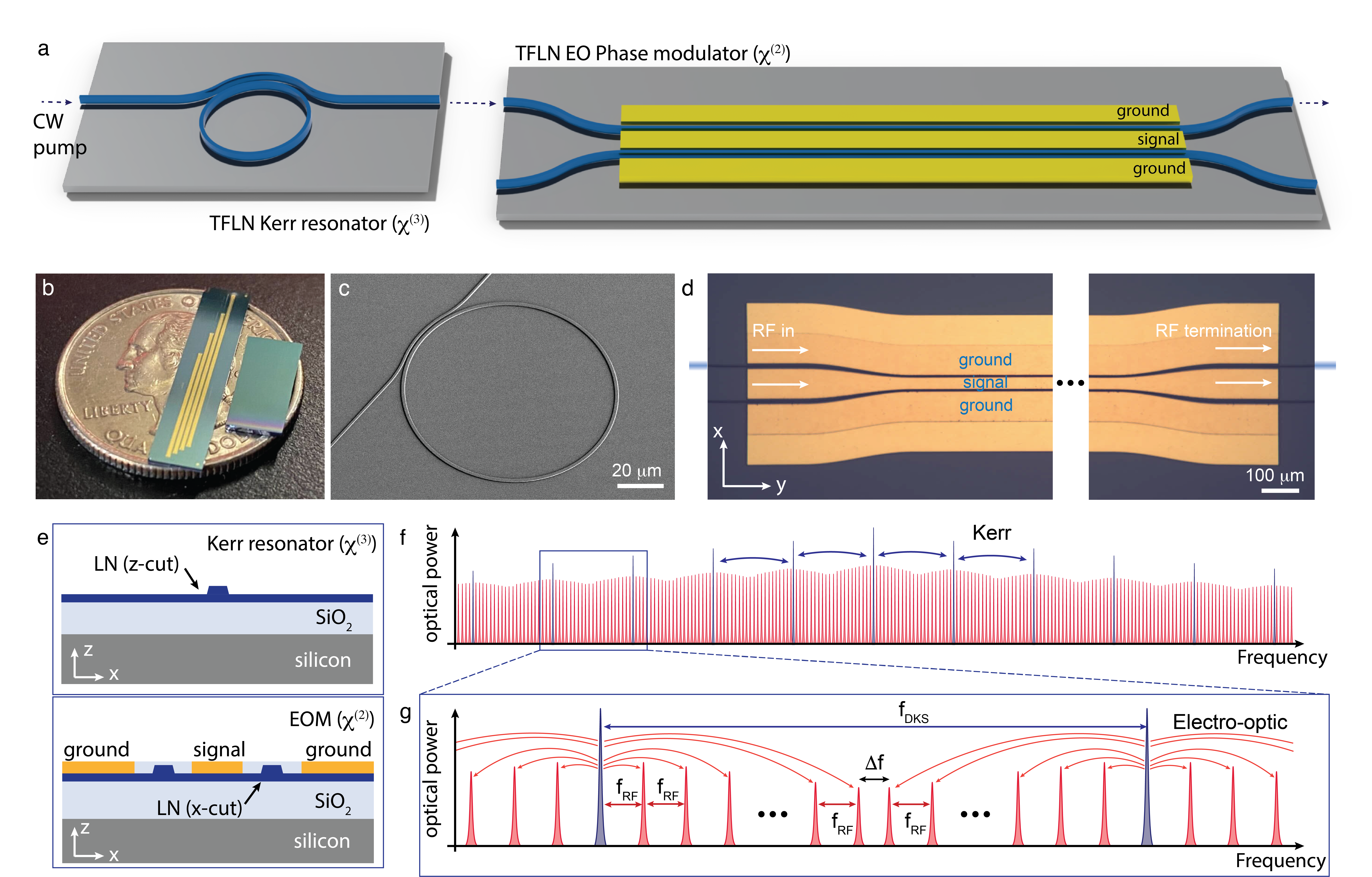
Our hybrid Kerr-EO approach for frequency comb generation on TFLN cascades a dispersion-engineered microresonator and a high-speed, efficient EO phase modulator. The microresonator outputs a DKS comb with a comb spacing in the range of hundreds of GHz. Each soliton line is subsequently phase modulated, and EO sidebands are formed in a cascaded manner around each DKS comb line such that the original DKS comb spacing is fully divided into microwave-rate spacing set by the EO modulation frequency. The required integrated-photonic components are schematically shown in Fig. 1a. Taking this approach, we developed Kerr microresonators and EO phase modulators on Z-cut and X-cut TFLN chips, respectively. Images of the fabricated Kerr microresonators and EO phase modulator are shown in Fig. 1b-e. The working principle of the hybrid Kerr-EO approach and final frequency comb output is schematically illustrated in Fig. 1f, g.
Octave-spanning DKS on TFLN
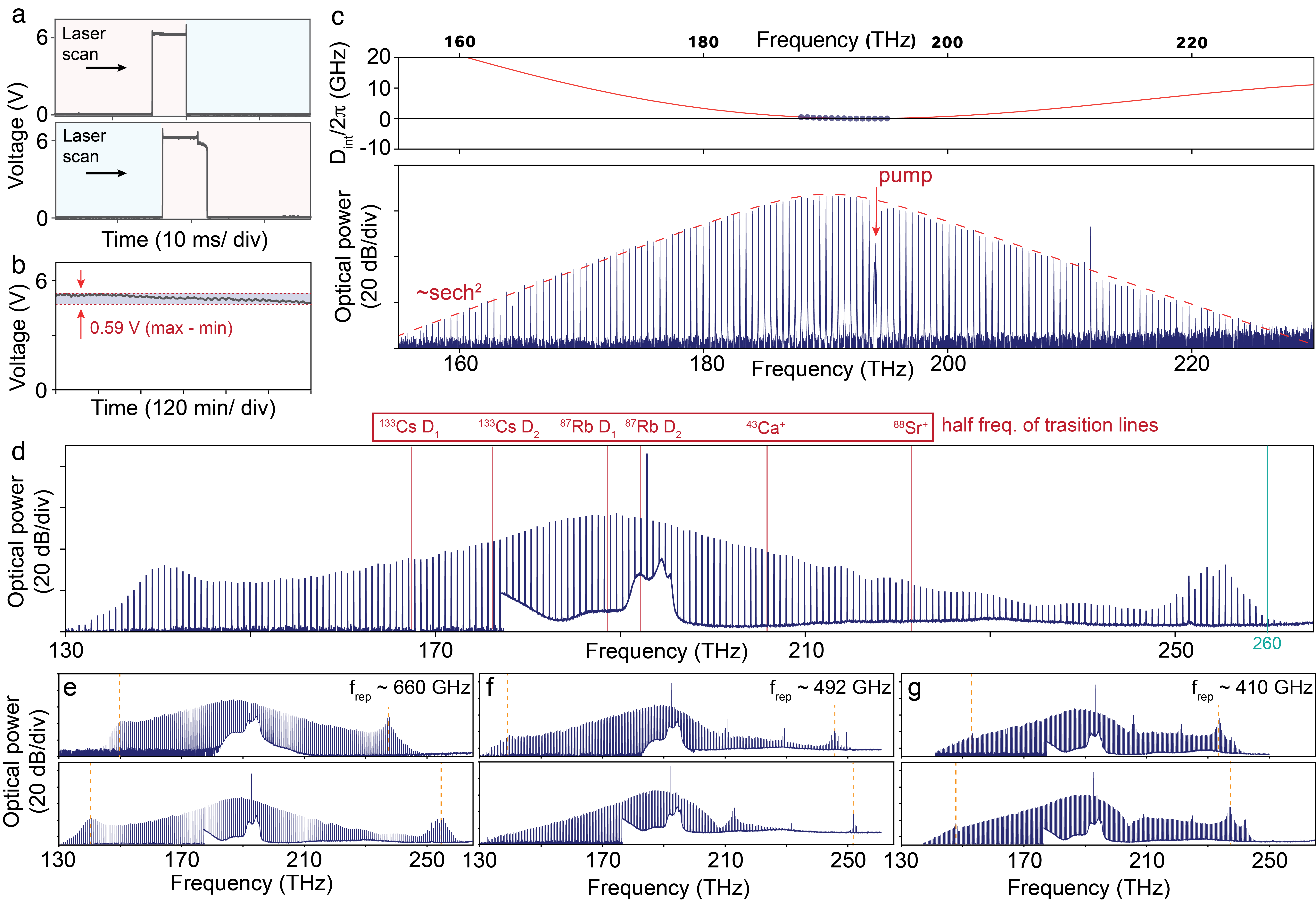
The TFLN photonic platform is a prime candidate on which to implement the hybrid Kerr-EO approach for broadband, microwave-rate frequency comb generation, due to its large Kerr and EO nonlinearities. It hosts low-loss microresonatorszhang2017monolithic supporting broadband DKS states initiated manuallyhe2019self , which also exhibit excellent free-running stabilitywan2023photorefraction , owing to the material’s photorefractive-induced, pump-resonance self-locking when the pump is red-detuned. Much like the thermo-optic self-stability of microresonatorscarmon2004dynamical when driven by a blue-detuned pump, common to nearly all other photonic platforms, the TFLN microresonator resonances stabilize against fluctuations in the pump frequency when the pump is on the red-side of resonance, which coincides with the region of DKS existence. This phenomenon differs from DKS generation in other platforms, where thermo-optic bistability under a red-detuned pump hinders stabilization into a DKS stateherr2014temporal . The self-starting nature of DKSs on TFLN simplifies the system complexity involved in their formation and stabilization. In Fig. 2a, we show that for a suitable resonance, when the pump frequency slowly sweeps across resonance starting from the red or blue detuned side, flat steps indicative of DKS states are present, irrespective of the initial condition. Once a DKS state emerges it is self-stable, as evidenced in Fig. 2b by the finite DKS power measured over 15 hours without any feedback acting on the microresonator or the pump laser. We show a prototypical single DKS state generated in the fundamental transverse-electric mode in Fig. 2c, where a strong quadratic term dominates the total microresonator dispersion , giving rise to a spectrum under a moderate on-chip pump power of 189 mW.
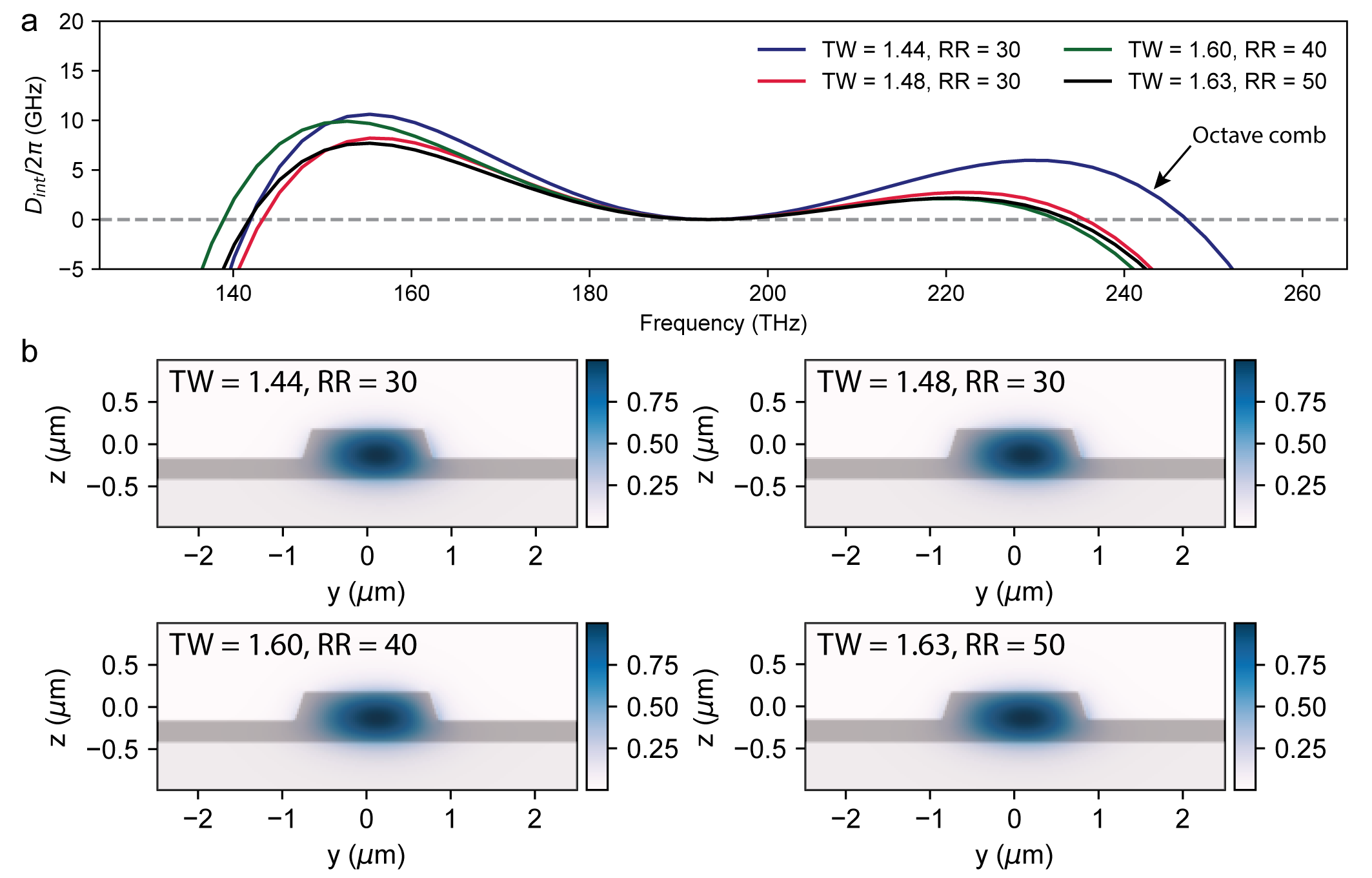
To further unlock the potential of DKSs in TFLN, we demonstrate an octave-spanning single soliton frequency comb from 131.3 THz to 263.8 THz with a spacing of 660 GHz, initiated under 372 mW of on-chip pump power (Fig. 2d). This is enabled by dispersion engineering via precisely tuning the radius, waveguide width, and waveguide height (etch depth) of the TFLN microresonators: for the three ring radii chosen (30, 40, and 50 m in Fig. 2e-g, respectively), we vary the microresonator waveguide width (decreasing width from top to bottom panels, in each of Fig. 2e-g) while fixing the waveguide height to about 345 nm. Using on-chip pump powers between 100 and 250 mW, we consistently generate well-controlled DKS spectra broadened by dual dispersive wavesbrasch2016photonic ; li2017stably ; spencer2018optical into frequencies of normal dispersion, significantly increasing the comb spans. As the waveguide width is decreased, the total comb span broadens as the dispersive wave locations move away from the pump, consistent with expectation (Methods). The broadband DKSs, initiated under moderate on-chip pump powers, serve as ideal sources for practical hybrid Kerr-EO combs.
High-speed EO modulation on TFLN
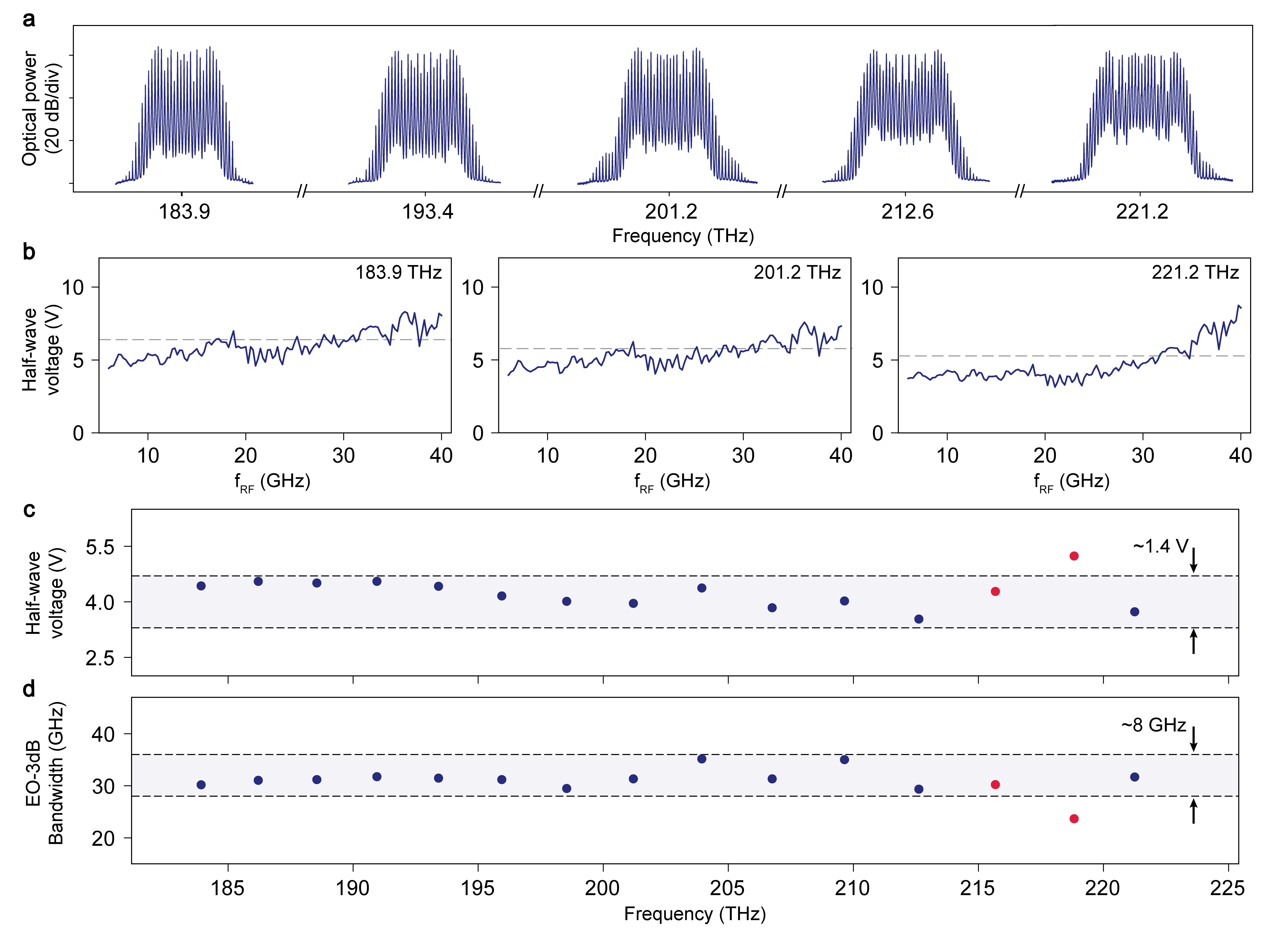
Next, we characterize the second piece to our approach, a TFLN EO phase modulator operated at multiple wavelengths sampled within the source DKS bandwidth. The waveguide-based integrated modulator operates with a travelling-wave electrode configuration. 2 cm-long microwave strip lines are used to induce a larger optical phase shift and reduce the Vπ value, simultaneously exhibiting large operational bandwidthwang2018integrated . Single-tone microwaves at frequency 29.158 GHz are continuously delivered to the EO phase modulator electrodes. It is important to note that the waveguide-based modulator operates with a broad, uninterrupted microwave band, over a continuous optical frequency span, as opposed to the cavity-based modulatorsgong2022monolithic . Additionally, our broadband modulator can significantly ease the complexity involved in f-2f stabilization on a chipspencer2018optical – the carrier offset frequency, often larger than the detector bandwidth, can be divided down using the modulator. Fig. 3 presents a broadband operation of our modulator at both microwave and optical frequencies.
Five continuous-wave optical frequencies in the telecommunications L, C, S, and E bands are separately coupled onto the chip through bilayer-taper mode converters, and EO sidebands are generated around each frequency, as shown in Fig. 3a. At all wavelengths, the microwave electrical power is estimated to be 4.47 W (36.5 dBm), showcasing the excellent power-handling capability of our modulator. We characterized the modulator half-wave voltage () and EO bandwidth at these wavelengths by measuring the modulation-frequency dependent (Methods), and the results are shown in Fig. 3b-d. While the and EO bandwidth show slight dependencies on the optical wavelength, likely due to varying optical-microwave spatial mode overlaps and dispersion-induced velocity mismatcheswang2018integrated , they are sufficient considering the total bandwidth of our DKS combs and the required number of EO sidebands for complete EO division of their spacings.
Hybrid Kerr-EO integrated frequency comb
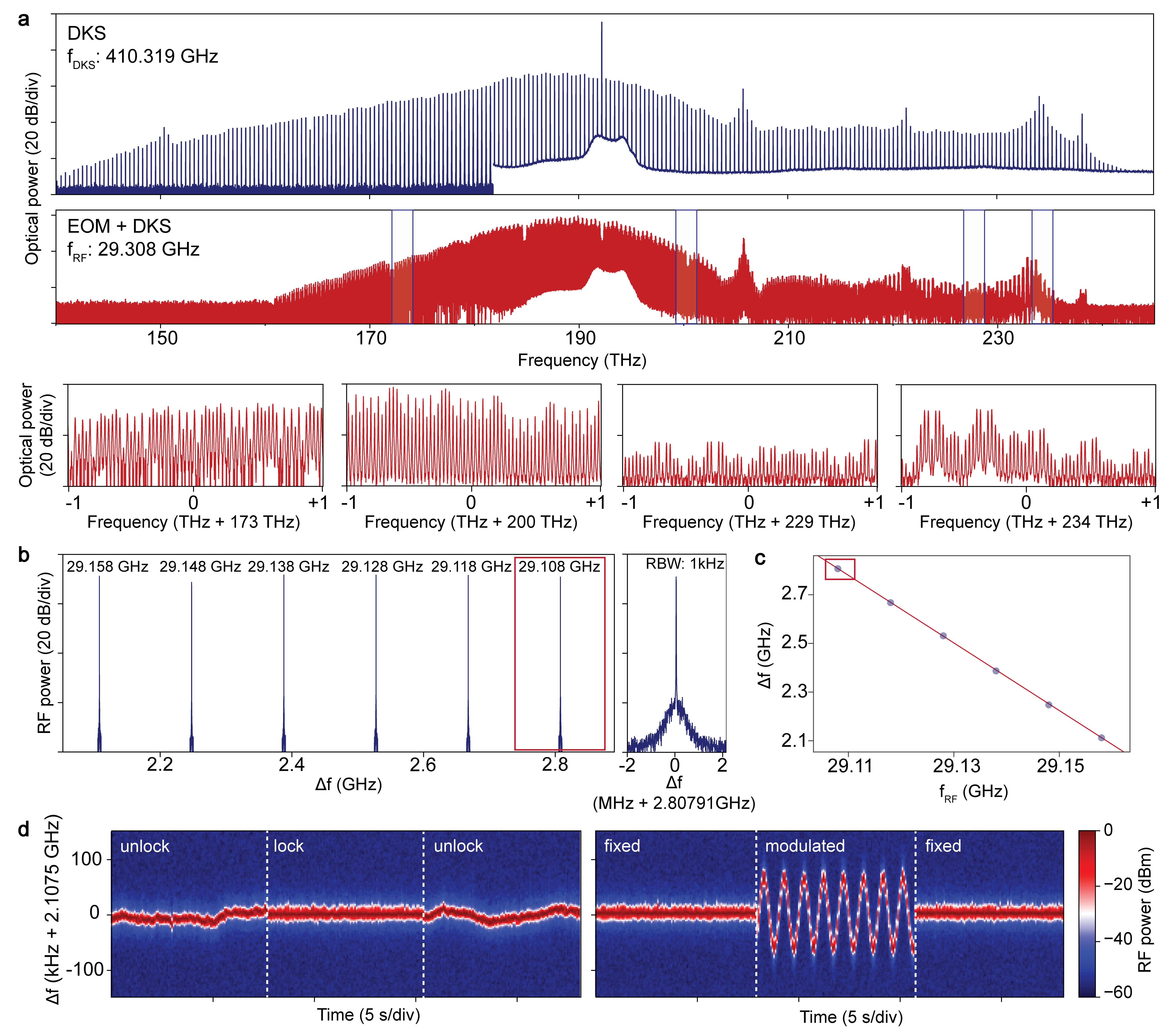
Combining self-starting and stable TFLN DKSs with efficient and high-speed EO modulation, a fully integrated hybrid Kerr-EO comb is realizable. By sending a low-threshold, 410.319 GHz-spaced DKS into our EO phase modulator, we obtain a hybrid Kerr-EO comb spanning 75.9 THz end-to-end with a spacing of 29.308 GHz (Fig. 4a). The relationship between the spacings is given by , where and are the DKS and hybrid Kerr-EO comb spacings, is the number of EO sidebands to fully divide one DKS spacing, and is the difference frequency from perfect EO division. These quantities are also schematically illustrated in Fig. 1g. Note that is the largest integer for which holds. When the EO sidebands perfectly divide the DKS spacing, and . The DKS spectrum is filled in with microwave-separated EO lines, as shown in the zoom-in windows of Fig. 4a. Power variation in the comb lines within each window comes from the EO sideband envelope determined by the local modulation depth, and that between windows comes from the frequency-dependent . The optical pump power for DKS generation is 125 mW (21 dBm) and the electrical power to drive the EO phase modulator is 2.51 W (34.5 dBm), both on-chip. The excellent connectivity of our comb offers densely positioned optical frequency references over its entire bandwidth. The free-running uptime of this broadband reference is determined by that of the source DKS, which we have shown, in Fig. 2b, can be more than 15 hours even in an uncontrolled environment. It is also important to note that our setup didn’t incorporate any external optical amplifiers or dispersion compensating elements between the DKS and EOM chips.
Next, we set to be a nonzero value of around 2.107 GHz to elucidate the spacing relationship. As the microwave drive frequency (which sets ) is linearly decreased in steps of 0.01 GHz, the linearly increases, as shown in Fig. 4b. Fitting against , the slope gives precisely in support of the spacing relationship. Confirming this relationship, our single integrated EO phase modulator thus demonstrated a direct measurement of the near THz spacing. Importantly, this measurement via efficient EO division transduces the near THz spacing into a GHz difference frequency compatible with detection via fast electronics. Further, the detected may then be compared and phase locked to a stable microwave reference by feeding back onto the DKS pump frequency, which in turn stabilizes the original DKS spacing. In Fig. 4d, we phase lock the around 2.107 GHz to 32 times a microwave reference oscillator set at frequency 65.865 MHz. When unlocked, the fluctuates according to the fluctuation in . When the lock is engaged, is pinned to a center frequency of 2.107 GHz with a 30 kHz linewidth. Sinusoidally modulating the reference oscillator frequency during the phase lock, the follows the reference modulation and so does , indicating detection-based, integrated EO control over the near THz-rate DKS spacing. Such a method for DKS spacing control stands in contrast to EO-based parametric seeding techniques which may only control microwave-rate, span-limited Kerr combshe2023high ; papp2013parametric or, in principle, seed THz combs with very poor duty cycles. Thus, our hybrid Kerr-EO approach towards TFLN-based frequency combs not only generates broadband, microwave-rate combs, but also opens a route towards on-chip methods for the detection, stabilization, and control over large DKS spacings located in previously inaccessible THz regimes.
III Conclusion and outlook
In summary, we outlined a hybrid Kerr-EO approach for integrated frequency comb generation and demonstrated TFLN as a material platform that realizes this approach completely. Our work is enabled by the outstanding second and third-order nonlinear properties of TFLN, hosting self-starting, low threshold, and stable free-running THz-rate DKSs, while supporting on-chip EO phase modulation capabilities with excellent bandwidth, efficiency, and speed. Currently, the comb line power difference between the DKS source and the hybrid Kerr-EO comb is attributed to EO power redistribution into the sidebands (about 10 dB pump mode suppression near 1550 nm), the off-chip coupling loss from the DKS chip (about 6 dB), and the insertion loss of the EO modulator chip (about 8 dB, both chip facets and propagation loss included). The latter two losses, totaling 14 dB, does not present a fundamental limitation and can be reduced significantly using improved coupling methods such as hybrid integration taking advantage of low-loss, multi-layer couplersliu2022ultra or monolithic integration of TFLN crystal cutszhou2023monolithically . The excess fiber length between the chips (more than 10 meters) led to attenuation of longer wavelength components due to silica absorption, a source of loss which also may be eliminated by advanced coupling methods. We note that the device stack of both DKS and EO phase modulator chips are sufficiently similar for the seamless implementation of these methods. Further, the electrical power requirement of driving the EO phase modulator may be significantly reduced down to hundreds of milliwatts, employing state-of-the-art modulators (Methods)xu2022dual ; zhu2022spectral .
Our integrated comb source, serving as a broadband, microwave-rate frequency reference spanning 75.9 THz around the telecommunications band, is suitable for the measurement, control, and mutual stabilization of optical frequencies. Such frequencies may take the form of independent chip-scale lasersjin2021hertz ; de2021iii ; shams2022electrically ; li2022integrated ; guo2023ultrafast ; snigirev2023ultrafast for gap-free and frequency-accurate laser spectroscopydel2009frequency ; shi2023frequency . Full stabilization of the hybrid Kerr-EO reference, such that the carrier-envelope offset frequency and comb spacing are simultaneously locked, can be facilitated through Kerr-induced synchronizationmoille2023kerr , interferometric self-referencingspencer2018optical ; brasch2017self , or electronic feedback locking of a comb line to a stable atomic transitionpapp2014microresonator ; newman2019architecture . Notably, in many applications, a fully connected comb over the entire DKS span may not be necessary and a locked THz-rate DKS spacing is sufficient. The demonstrated locking and modulation of the difference frequency of our hybrid Kerr-EO comb enables direct stabilization and control of the original, large DKS spacing, which may form the basis for THz-related applications such as radar and high-bandwidth wireless communicationskoenig2013wireless ; wang2021towards . Further, a hybrid Kerr-EO comb may extend conventional opticalfortier2011generation ; xie2017photonic ; liu2020photonic ; tetsumoto2021optically ; kudelin2023photonic ; sun2023integrated and EOli2014electro frequency division schemes towards integrated synthesizers of ultra-stable microwaves that promise orders of magnitude improvement in division factor when a cascaded DKS-EO frequency division is considered. Therefore, our integrated hybrid Kerr-EO frequency comb may lay the foundation for a variety of next-generation chip-scale devices that play a key role in system-level applicationsmarin2017microresonator ; Bhaskaran:2021:Nature ; Moss:2021:Nature ; spencer2018optical ; kudelin2023photonic ; sun2023integrated of integrated photonics, where the power of optical frequency combsdiddams2020optical is paramount.
References
- (1) Udem, T., Holzwarth, R. & Hänsch, T. W. Optical frequency metrology. Nature 416, 233–237 (2002).
- (2) Diddams, S. A., Vahala, K. & Udem, T. Optical frequency combs: Coherently uniting the electromagnetic spectrum. Science 369, eaay3676 (2020).
- (3) Suh, M.-G., Yang, Q.-F., Yang, K. Y., Yi, X. & Vahala, K. J. Microresonator soliton dual-comb spectroscopy. Science 354, 600–603 (2016).
- (4) Coddington, I., Newbury, N. & Swann, W. Dual-comb spectroscopy. Optica 3, 414–426 (2016).
- (5) Picqué, N. & Hänsch, T. W. Frequency comb spectroscopy. Nature Photonics 13, 146–157 (2019).
- (6) Spencer, D. T. et al. An optical-frequency synthesizer using integrated photonics. Nature 557, 81–85 (2018).
- (7) Fortier, T. M. et al. Generation of ultrastable microwaves via optical frequency division. Nature Photonics 5, 425–429 (2011).
- (8) Li, J., Yi, X., Lee, H., Diddams, S. A. & Vahala, K. J. Electro-optical frequency division and stable microwave synthesis. Science 345, 309–313 (2014).
- (9) Xie, X. et al. Photonic microwave signals with zeptosecond-level absolute timing noise. Nature photonics 11, 44–47 (2017).
- (10) Liu, J. et al. Photonic microwave generation in the x-and k-band using integrated soliton microcombs. Nature Photonics 14, 486–491 (2020).
- (11) Tetsumoto, T. et al. Optically referenced 300 ghz millimetre-wave oscillator. Nature Photonics 15, 516–522 (2021).
- (12) Papp, S. B. et al. Microresonator frequency comb optical clock. Optica 1, 10–14 (2014).
- (13) Newman, Z. L. et al. Architecture for the photonic integration of an optical atomic clock. Optica 6, 680–685 (2019).
- (14) Herr, T. et al. Temporal solitons in optical microresonators. Nature Photonics 8, 145–152 (2014).
- (15) Kippenberg, T. J., Gaeta, A. L., Lipson, M. & Gorodetsky, M. L. Dissipative kerr solitons in optical microresonators. Science 361, eaan8083 (2018).
- (16) Zhang, M. et al. Broadband electro-optic frequency comb generation in a lithium niobate microring resonator. Nature 568, 373–377 (2019).
- (17) Rueda, A., Sedlmeir, F., Kumari, M., Leuchs, G. & Schwefel, H. G. Resonant electro-optic frequency comb. Nature 568, 378–381 (2019).
- (18) Hu, Y. et al. High-efficiency and broadband on-chip electro-optic frequency comb generators. Nature Photonics 16, 679–685 (2022).
- (19) Yu, M. et al. Integrated femtosecond pulse generator on thin-film lithium niobate. Nature 612, 252–258 (2022).
- (20) Boes, A. et al. Lithium niobate photonics: Unlocking the electromagnetic spectrum. Science 379, eabj4396 (2023).
- (21) Shi, B. et al. Frequency-comb-linearized, widely tunable lasers for coherent ranging. arXiv preprint arXiv:2308.15875 (2023).
- (22) Koenig, S. et al. Wireless sub-thz communication system with high data rate. Nature Photonics 7, 977–981 (2013).
- (23) Wang, B. et al. Towards high-power, high-coherence, integrated photonic mmwave platform with microcavity solitons. Light: Science & Applications 10, 4 (2021).
- (24) Marin-Palomo, P. et al. Microresonator-based solitons for massively parallel coherent optical communications. Nature 546, 274–279 (2017).
- (25) Jørgensen, A. et al. Petabit-per-second data transmission using a chip-scale microcomb ring resonator source. Nature Photonics 16, 798–802 (2022).
- (26) Yang, K. Y. et al. Multi-dimensional data transmission using inverse-designed silicon photonics and microcombs. Nature Communications 13, 7862 (2022).
- (27) Rizzo, A. et al. Massively scalable kerr comb-driven silicon photonic link. Nature Photonics 17, 781–790 (2023).
- (28) Ludlow, A. D., Boyd, M. M., Ye, J., Peik, E. & Schmidt, P. O. Optical atomic clocks. Reviews of Modern Physics 87, 637 (2015).
- (29) Keller, U. Recent developments in compact ultrafast lasers. Nature 424, 831–838 (2003).
- (30) Dudley, J. M., Genty, G. & Coen, S. Supercontinuum generation in photonic crystal fiber. Reviews of modern physics 78, 1135 (2006).
- (31) Xiang, C. et al. 3d integration enables ultralow-noise isolator-free lasers in silicon photonics. Nature 620, 78–85 (2023).
- (32) Kudelin, I. et al. Photonic chip-based low noise microwave oscillator. arXiv preprint arXiv:2307.08937 (2023).
- (33) Sun, S. et al. Integrated optical frequency division for stable microwave and mmwave generation. arXiv preprint arXiv:2305.13575 (2023).
- (34) Chang, L., Liu, S. & Bowers, J. E. Integrated optical frequency comb technologies. Nature Photonics 16, 95–108 (2022).
- (35) Li, Q. et al. Stably accessing octave-spanning microresonator frequency combs in the soliton regime. Optica 4, 193–203 (2017).
- (36) Pfeiffer, M. H. et al. Octave-spanning dissipative kerr soliton frequency combs in microresonators. Optica 4, 684–691 (2017).
- (37) Liu, X. et al. Aluminum nitride nanophotonics for beyond-octave soliton microcomb generation and self-referencing. Nature Communications 12, 5428 (2021).
- (38) Weng, H. et al. Directly accessing octave-spanning dissipative kerr soliton frequency combs in an aln microresonator. Photonics Research 9, 1351–1357 (2021).
- (39) Anderson, M. H. et al. Zero dispersion kerr solitons in optical microresonators. Nature communications 13, 4764 (2022).
- (40) Cheng, R. et al. On-chip synchronous pumped optical parametric oscillator on thin-film lithium niobate. arXiv preprint arXiv:2304.12878 (2023).
- (41) Del’Haye, P., Papp, S. B. & Diddams, S. A. Hybrid electro-optically modulated microcombs. Physical review letters 109, 263901 (2012).
- (42) Drake, T. E. et al. Terahertz-rate kerr-microresonator optical clockwork. Physical Review X 9, 031023 (2019).
- (43) Moille, G. et al. Kerr-induced synchronization of a cavity soliton to an optical reference. Nature 624, 267–274 (2023).
- (44) Gong, Z., Shen, M., Lu, J., Surya, J. B. & Tang, H. X. Monolithic kerr and electro-optic hybrid microcombs. Optica 9, 1060–1065 (2022).
- (45) He, Y. et al. High-speed tunable microwave-rate soliton microcomb. Nature Communications 14, 3467 (2023).
- (46) Wang, C. et al. Integrated lithium niobate electro-optic modulators operating at cmos-compatible voltages. Nature 562, 101–104 (2018).
- (47) Xu, M. et al. Dual-polarization thin-film lithium niobate in-phase quadrature modulators for terabit-per-second transmission. Optica 9, 61–62 (2022).
- (48) Wang, C. et al. Ultrahigh-efficiency wavelength conversion in nanophotonic periodically poled lithium niobate waveguides. Optica 5, 1438–1441 (2018).
- (49) Lu, J. et al. Periodically poled thin-film lithium niobate microring resonators with a second-harmonic generation efficiency of 250,000%/w. Optica 6, 1455–1460 (2019).
- (50) McKenna, T. P. et al. Ultra-low-power second-order nonlinear optics on a chip. Nature Communications 13, 4532 (2022).
- (51) Zhu, D. et al. Integrated photonics on thin-film lithium niobate. Advances in Optics and Photonics 13, 242–352 (2021).
- (52) Zhang, M., Wang, C., Cheng, R., Shams-Ansari, A. & Lončar, M. Monolithic ultra-high-q lithium niobate microring resonator. Optica 4, 1536–1537 (2017).
- (53) He, Y. et al. Self-starting bi-chromatic LiNbO3 soliton microcomb. Optica 6, 1138–1144 (2019).
- (54) Wan, S. et al. Photorefraction-assisted self-emergence of dissipative kerr solitons. arXiv preprint arXiv:2305.02590 (2023).
- (55) Carmon, T., Yang, L. & Vahala, K. J. Dynamical thermal behavior and thermal self-stability of microcavities. Optics express 12, 4742–4750 (2004).
- (56) Brasch, V. et al. Photonic chip–based optical frequency comb using soliton cherenkov radiation. Science 351, 357–360 (2016).
- (57) Papp, S. B., Del’Haye, P. & Diddams, S. A. Parametric seeding of a microresonator optical frequency comb. Optics Express 21, 17615–17624 (2013).
- (58) Liu, X. et al. Ultra-broadband and low-loss edge coupler for highly efficient second harmonic generation in thin-film lithium niobate. Advanced Photonics Nexus 1, 016001–016001 (2022).
- (59) Zhou, Y. et al. Monolithically integrated active passive waveguide array fabricated on thin film lithium niobate using a single continuous photolithography process. Laser & Photonics Reviews 17, 2200686 (2023).
- (60) Zhu, D. et al. Spectral control of nonclassical light pulses using an integrated thin-film lithium niobate modulator. Light: Science & Applications 11, 327 (2022).
- (61) Jin, W. et al. Hertz-linewidth semiconductor lasers using cmos-ready ultra-high-q microresonators. Nature Photonics 15, 346–353 (2021).
- (62) de Beeck, C. O. et al. III/V-on-lithium niobate amplifiers and lasers. Optica 8, 1288–1289 (2021).
- (63) Shams-Ansari, A. et al. Electrically pumped laser transmitter integrated on thin-film lithium niobate. Optica 9, 408–411 (2022).
- (64) Li, M. et al. Integrated pockels laser. Nature communications 13, 5344 (2022).
- (65) Guo, Q. et al. Ultrafast mode-locked laser in nanophotonic lithium niobate. Science 382, 708–713 (2023).
- (66) Snigirev, V. et al. Ultrafast tunable lasers using lithium niobate integrated photonics. Nature 615, 411–417 (2023).
- (67) Del’Haye, P., Arcizet, O., Gorodetsky, M. L., Holzwarth, R. & Kippenberg, T. J. Frequency comb assisted diode laser spectroscopy for measurement of microcavity dispersion. Nature photonics 3, 529–533 (2009).
- (68) Brasch, V., Lucas, E., Jost, J. D., Geiselmann, M. & Kippenberg, T. J. Self-referenced photonic chip soliton kerr frequency comb. Light: Science & Applications 6, e16202–e16202 (2017).
- (69) Feldmann, J. et al. Parallel convolutional processing using an integrated photonic tensor core. Nature 589, 52–58 (2021).
- (70) Xu, X. et al. 11 tops photonic convolutional accelerator for optical neural networks. Nature 589, 44–51 (2021).
- (71) He, L. et al. Low-loss fiber-to-chip interface for lithium niobate photonic integrated circuits. Optics letters 44, 2314–2317 (2019).
- (72) Yuan, Z. et al. Soliton pulse pairs at multiple colors in normal dispersion microresonators. arXiv preprint arXiv:2301.10976 (2023).
- (73) Xue, X. et al. Mode-locked dark pulse kerr combs in normal-dispersion microresonators. Nature Photonics 9, 594–600 (2015).
- (74) Helgason, Ó. B. et al. Surpassing the nonlinear conversion efficiency of soliton microcombs. Nature Photonics 17, 992–999 (2023).
- (75) Jung, H. et al. Tantala kerr nonlinear integrated photonics. Optica 8, 811–817 (2021).
- (76) Yi, X., Yang, Q.-F., Yang, K. Y., Suh, M.-G. & Vahala, K. Soliton frequency comb at microwave rates in a high-q silica microresonator. Optica 2, 1078–1085 (2015).
- (77) Wu, L. et al. Algaas soliton microcombs at room temperature. Optics Letters 48, 3853–3856 (2023).
- (78) Gong, Z., Liu, X., Xu, Y. & Tang, H. X. Near-octave lithium niobate soliton microcomb. Optica 7, 1275–1278 (2020).
- (79) Guidry, M. A., Lukin, D. M., Yang, K. Y., Trivedi, R. & Vučković, J. Quantum optics of soliton microcombs. Nature Photonics 16, 52–58 (2022).
- (80) Hausmann, B., Bulu, I., Venkataraman, V., Deotare, P. & Lončar, M. Diamond nonlinear photonics. Nature Photonics 8, 369–374 (2014).
- (81) Wilson, D. J. et al. Integrated gallium phosphide nonlinear photonics. Nature Photonics 14, 57–62 (2020).
- (82) Moille, G., Lu, X., Stone, J., Westly, D. & Srinivasan, K. Fourier synthesis dispersion engineering of photonic crystal microrings for broadband frequency combs. Communications Physics 6, 144 (2023).
- (83) Yu, S.-P. et al. Spontaneous pulse formation in edgeless photonic crystal resonators. Nature Photonics 15, 461–467 (2021).
- (84) Lucas, E., Yu, S.-P., Briles, T. C., Carlson, D. R. & Papp, S. B. Tailoring microcombs with inverse-designed, meta-dispersion microresonators. Nature Photonics 17, 943–950 (2023).
- (85) Yang, Q.-F., Yi, X., Yang, K. Y. & Vahala, K. Stokes solitons in optical microcavities. Nature Physics 13, 53–57 (2017).
- (86) Bao, H. et al. Laser cavity-soliton microcombs. Nature Photonics 13, 384–389 (2019).
- (87) Bruch, A. W. et al. Pockels soliton microcomb. Nature Photonics 15, 21–27 (2021).
- (88) Cole, D. C., Lamb, E. S., Del’Haye, P., Diddams, S. A. & Papp, S. B. Soliton crystals in kerr resonators. Nature Photonics 11, 671–676 (2017).
- (89) Stern, B., Ji, X., Okawachi, Y., Gaeta, A. L. & Lipson, M. Battery-operated integrated frequency comb generator. Nature 562, 401–405 (2018).
- (90) Shen, B. et al. Integrated turnkey soliton microcombs. Nature 582, 365–369 (2020).
- (91) Kim, B. Y. et al. Turn-key, high-efficiency kerr comb source. Optics letters 44, 4475–4478 (2019).
- (92) Raja, A. S. et al. Electrically pumped photonic integrated soliton microcomb. Nature communications 10, 680 (2019).
IV Methods
Device fabrication and parameters
Dissipative Kerr soliton (DKS) devices are fabricated on a Z-cut thin-film lithium niobate (Z-TFLN) on insulator wafer supplied by NanoLN. The initial film thickness is 600 nm of Z-TFLN on top of 2 m thermal oxide and 0.525 mm silicon. Nanophotonic waveguides are patterned on hydrogen silsesquioxane (HSQ) resist using electron-beam lithography (EBL). The patterned resist undergoes multiple iterations of Ar+-based reactive ion etching and wet etching until an etch depth of about 345 nm is reached, leaving about 255 nm of slab. This iterative etching process results in a waveguide sidewall angle of about 72 degrees, owing to the prevention of excess redeposition buildup during the dry-etching process. Finally, the HSQ resist is stripped using dilute hydrogen-fluoride (HF) and the devices are annealed in a high temperature, oxygen-rich environment. Routing waveguides for coupling light on and off the chip are exposed through manual cleaving, resulting in coupling losses of about 6 dB per facet.
Electro-optic (EO) phase modulator devices are fabricated on a X-cut thin-film lithium niobate (X-TFLN) on insulator wafer supplied by NanoLN. The initial film thickness is 600 nm of X-TFLN on top of 2 m thermal oxide and 0.525 mm silicon. The fabrication process is identical to that for DKS devices up to etching of the waveguides (320 nm etch depth and 280 nm slab, instead). Plasma-enhanced chemical vapor deposition (PECVD) is used to deposit a silica top cladding layer. Bilayer taper mode converters are fabricated by first opening photolithography-defined rectangular windows in the top cladding using HF wet etching. Subsequently, the mode converter tips are defined using aligned EBL and another round of Ar+-based reactive ion etching. Finally, the devices are cleaned and cladded with PECVD silica once again. Two centimeter long gold microwave electrodes are defined near the waveguides using aligned EBL and photolithography and metalized using electron-beam deposition followed by liftoff process. Facets at the mode converter tips are exposed through reactive ion etching through the X-TFLN, thermal oxide, and silicon, resulting in a total EO phase modulator insertion loss of about 8 dB. The 6 GHz half-wave-voltage () is about 4 V when optically pumped in the C-band.
Microresonator dispersion engineering
The microresonator dispersion is defined by the integrated dispersion , where is the azimuthal mode indexbrasch2016photonic . The dispersion parameters are directly obtained from eigenmode simulations of the fundamental transverse electric (TE) mode effective refractive index (), directly due to engineered microresonator waveguide cross-sections. We carry out such simulations using a commercial eigenmode solver (Lumerical MODE) including waveguide bending. We present the simulation of for all DKS states in Fig. 2e-g, alongside representative fundamental Transverse Electric (TE) modal profiles for various waveguide cross-sectional geometries in Extended Fig. 1. In these figures, the waveguide width is varied across different microresonator radii, with the waveguide height (etch depth) consistently maintained at approximately 345 nm. This effectively illustrates how the positions of dispersive waves are influenced by the waveguide width parameter. In Fig. 2c, the experimental in a narrow band around the pump wavelength (1520-1630 nm) is measured by fitting the measured resonance positions of the microresonator, where their frequencies are calibrated by a fiber-based Mach-Zehnder interferometer with a fringe period of 191.3 MHz. The good agreement between simulated and experimental dispersive wave positions and suggests predictable dispersion engineering for broadband DKS states in the TFLN platform.
Dissipative Kerr soliton device characterization
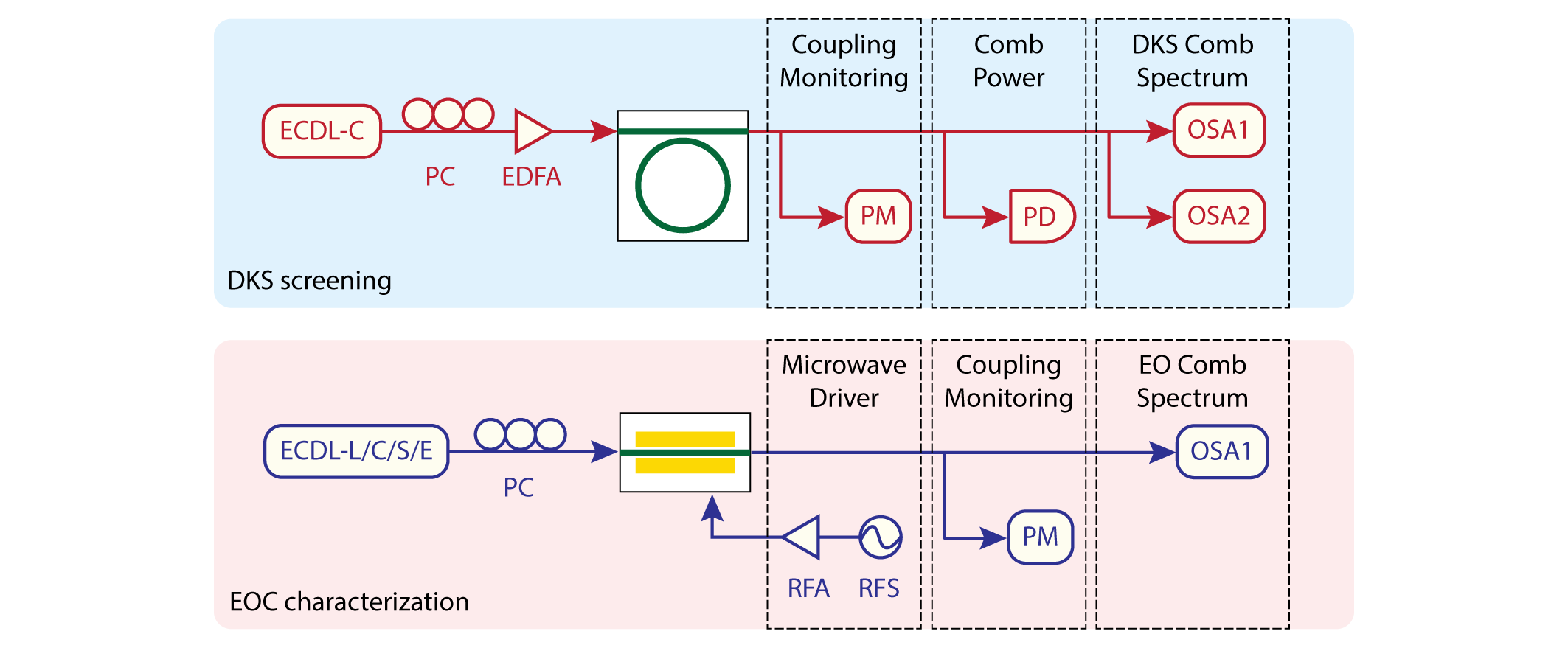
The experimental setup for DKS device characterization and soliton generation is schematically illustrated in Extended Fig. 2. A continuous-wave (CW) pump laser is amplified by an erbium-doped fiber amplifier (EDFA). In Fig. 2c, a tunable bandpass filter was used to filter out the amplified spontaneous emission (ASE) associated noise with the pump power amplification. Further, a fiber-Bragg-grating (FBG) notch filter filters out the strong pump frequency component in the DKS spectrum. In Fig. 2d-g, the ASE was not removed from the spectrum and corresponds to the irregular shape beneath the DKS envelope. The pump was also not removed due to over ten-meters of compressed fiber in the notch filter, introducing excess fiber-induced losses. In both cases, polarization controllers and lensed fibers are used to couple light into the DKS chip. Lensed fibers are used to couple light off the DKS chip. One percent of the total output is used to monitor the fiber-to-chip in and out coupling. Ninety-nine percent is then split such that ten percent is sent to a 125 MHz photoreceiver to monitor the total comb power as a voltage readout on an oscilloscope and ninety percent is sent to two optical spectrum analyzers (OSAs, covering 600-1700 nm and 1200-2400 nm) to simultaneously monitor the comb spectrum. The comb power measurement during laser scanning back and forth through a microresonator resonance (Fig. 2a) is recorded by the oscilloscope voltage. The stability measurement (Fig. 2b), as the DKS state is maintained, consists of oscilloscope voltage values collected every 20 seconds over a total of 15 hours.
Electro-optic phase modulator performance characterization
The experimental setup for electro-optic (EO) phase modulator performance characterization is schematically illustrated in Extended Fig. 2. A CW pump laser passes through a polarization controller and is coupled on and off the EO phase modulator chip by lensed fibers. One percent of the total output is used to monitor the fiber-to-chip in and out coupling and polarization. Ninety-nine percent is sent to an OSA (covering 600-1700 nm) to monitor the EO comb spectrum, such as those in Fig. 3a, where five CW optical frequencies are sequentially coupled. The electrical power to generate these spectra is estimated to be about 4.47 W (36.5 dBm). This electrical power was chosen solely to demonstrate the power-handling capabilities of our modulator chip and a lower power level was used for hybrid Kerr-EO comb generation. Since the EO phase modulator is required to operate at all frequencies covering the source DKS span, our integrated phase modulator offers the uniquely existing on-chip solution while also being highly compact and power stable. We characterized its 6 GHz half-wave voltage () and the electro-optic bandwidth at fifteen optical wavelengths in the telecommunications L, C, S, and E bands, only limited by available lasers, using the methodology described below. At each wavelength, 137 modulation frequencies (6 GHz to 40 GHz in steps of 0.25 GHz) are applied at power levels of 5 and 10 dBm output directly from a calibrated microwave source. For each modulation frequency and source output power combination, the EO comb spectrum is collected and the power in each comb line extracted. The power of the EO sideband theoretically corresponds to the nth order Bessel function evaluated at a modulation depth given by . Since the power delivered onto the modulator gives , we fit the EO sideband powers and delivered microwave power (source output power corrected for microwave circuit losses) to obtain the at some modulation frequency and source output power combination. A single-valued for a given modulation frequency was obtained by averaging the two s extracted when the source output power was varied between 5 and 10 dBm. Averaging over more power levels was not necessary as they always yielded near identical , which further justifies averaging as only a means of reducing statistical variation in measurements at the same modulation frequency. Specifically, we repeated this vs. modulation frequency measurement at fifteen optical wavelengths of 1355 nm and 1370-1630 nm in intervals of 20 nm, and three representative curves were shown in Fig. 3b. The first value of each curve is taken to be the 6 GHz (plotted as data points in Fig. 3c), and the modulation frequency at which the rises to of its 6 GHz value is taken to be the EO 3 dB bandwidth (plotted as data points in Fig. 3d).
Hybrid Kerr-electro-optic comb generation
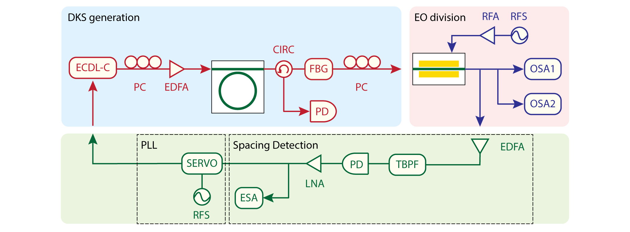
The experimental setup for hybrid Kerr-EO comb generation is schematically illustrated in Extended Fig. 2. It is a combination of the separate setups for DKS generation and EO phase modulator characterization, except the two chips are operated simultaneously, with an FBG notch filter to filter out the strong pump frequency component and a polarization controller linking the chips. Two OSAs are used to simultaneously monitor the comb spectrum. The measurement did not necessitate use of the FBG, and the polarization controller may be omitted in conceivable monolithic integration or low-loss coupling schemes between Z-TFLN and X-TFLN, due to the good spatial mode overlap between the fundamental TE modes in both cuts of thin-film material.
To generate the hybrid Kerr-EO combs as in Fig. 4a, the optical power on-chip was estimated to be 125 mW from an EDFA output power of 500 mW, accounting for a 6 dB coupling loss induced by the input facet. Notably, with bilayer taper mode converters such as those fabricated on the EO phase modulator chip, the coupling loss may be reduced to 1.7 dB per facet and the off-chip pump power requirement lowered to 188 mWhe2019low . Advanced coupler designs may be exploited for 0.54 dB loss per facet and the off-chip pump power requirement lowered to 142 mWliu2022ultra . Currently, the loaded quality factor () for our pump resonance in Fig. 4a is about 1 million. Fabrication improvements in by a factor of 2 may reduce the on-chip pump power requirement. Packaged distributed feedback (DFB) lasers can be butt-coupled to the DKS chip facet in combination with edge couplers to yield estimated facet losses conservatively around 3 dB.
The electrical power required to electro-optically divide 410.319 GHz of DKS spacing into microwave-rate (29.308 GHz) separated lines was calibrated to be 2.51 W (34.5 dBm) after accounting for microwave losses in the system, at 29.158 GHz modulation frequency. We specifically selected a microwave power such that the highest power sidebands would appear at the sideband. This choice ensures that the comb lines separated by the difference frequency would generate a microwave beatnote with high signal-to-noise ratio and phase locking to the stable microwave oscillator would yield a high-quality phase lock in the locking demonstration. The EO phase modulator measured in the C-band has a at 6 GHz modulation frequency and a 3 dB EO bandwidth of 31.47 GHz. The electrical power consumption may be further lowered by 5.3 dB using state-of-the-art TFLN EO phase modulators with (extrapolated from quoted for a dual-drive amplitude modulator)xu2022dual and 110 GHz 3 dB EO bandwidths. This projects an electrical power on-chip of 0.24 W (23.8 dBm), reaching sub-Watt levels. Dual-drive phase modulators in a loop-back architecture may be realizedzhu2022spectral , further lowering the projected electrical power on-chip by a factor of two, down to 0.12 W (20.8 dBm).
Soliton spacing detection, locking, and stabilization
When generating the hybrid Kerr-EO comb, a nonzero difference frequency is introduced when is not an integer multiple of . In our experiment in Fig. 4d (setup schematically illustrated in Extended Fig. 3), was locked at 2.107 GHz after detection by a 12 GHz bandwidth photoreceiver when was set to 29.158 GHz. The lock was maintained by electronic feedback onto the current control of the pump laser, controlling its frequency while residual laser intensity fluctuations are negligible. During this lock, was fixed at 410.319 GHz. To generate the beatnote on the photoreceiver, relevant EO sideband pairs were filtered then amplified by a C-band pre-amplifier before beating on the photoreceiver. The was further amplified by a low-noise microwave amplifier (providing about 26 dB of gain) to produce a sufficient beatnote power level for the phase locked loop (PLL). The PLL is based on a phase comparator circuit where the reference frequency is 32 times a signal generator set at 65.865 MHz. This signal generator is externally referenced by the 10 kHz clock signal synthesizing . In principle, the broadband, microwave-rate frequency reference provided by our hybrid Kerr-EO comb may be fully stabilized, that is, the frequency of each of the 2,589 comb lines can be precisely known, once both and of the frequency comb are stabilized. Here, we demonstrated the possibility for the detection, stabilization, and control of a near THz-rate using a single integrated EO phase modulator.
Comparison with other integrated frequency comb technologies
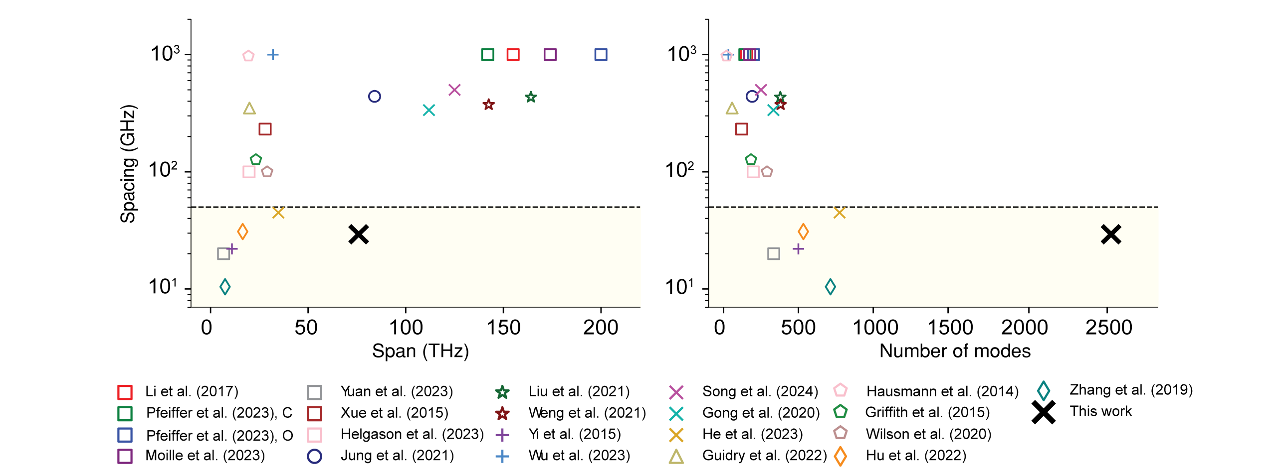
Comparing our work with state-of-the-art integrated frequency comb technologies surveying various material platforms, such as octave-spanning DKS combs and microresonator-based EO-combs, we find that the hybrid Kerr-EO comb of this work produces the largest span (75.9 THz) while simultaneously capable of directly interfacing with conventional fast-electronics, which we define as a sub-50 GHz spacing between adjacent comb lines. These features are augmented by a record number of 2,589 lines produced using a comb-generator consisting of purely integrated components. This comparison is graphically illustrated in Extended Fig. 4. All data points are directly quoted from references or estimated from figures when exact numbers are not reportedzhang2019broadband ; hu2022high ; he2023high ; moille2023kerr ; li2017stably ; pfeiffer2017octave ; yuan2023soliton ; xue2015mode ; helgason2023surpassing ; jung2021tantala ; liu2021aluminum ; weng2021directly ; yi2015soliton ; wu2023algaas ; gong2020near ; guidry2022quantum ; hausmann2014diamond ; wilson2020integrated . We note that significant achievements were made in integrated frequency combs beyond DKS or EO combs in the most conventional sense, such as ones utilizing advanced dispersion engineeringmoille2023fourier ; yu2021spontaneous ; lucas2023tailoring and additional nonlinear optical effectsyang2017stokes ; bao2019laser ; bruch2021pockels , soliton crystalscole2017soliton , and lower operational power and turnkey microcombsstern2018battery ; shen2020integrated ; kim2019turn ; raja2019electrically , which cannot be simply viewed by span, spacing, or number of comb lines.
Data availability The data that support the plots within this paper and other findings of this study are available from the corresponding author upon reasonable request.
Code availability The code used to produce the plots within this paper is available from the corresponding author upon reasonable request.
Acknowledgments
This work is supported by the Defense Advanced Research Projects Agency (D23AP00251-00, HR001120C0137), Office of Naval Research (N00014-22-C-1041), National Science Foundation (OMA-2137723, OMA-2138068), and National Research Foundation of Korea. The authors thank Rebecca Cheng for providing the phase modulator, Chaoshen Zhang, Hana Warner, Rebecca Cheng, and Neil Sinclair for discussions, and Letícia Magalhães and Jeremiah Jacobson for photography assistance. Y.S. acknowledges support from the AWS Generation Q Fund at the Harvard Quantum Initiative. All devices in this work were fabricated at the Harvard Center for Nanoscale Systems.