VoltSchemer: Use Voltage Noise to Manipulate Your Wireless Charger
Abstract
Wireless charging is becoming an increasingly popular charging solution in portable electronic products for a more convenient and safer charging experience than conventional wired charging. However, our research identified new vulnerabilities in wireless charging systems, making them susceptible to intentional electromagnetic interference. These vulnerabilities facilitate a set of novel attack vectors, enabling adversaries to manipulate the charger and perform a series of attacks.
In this paper, we propose VoltSchemer, a set of innovative attacks that grant attackers control over commercial-off-the-shelf wireless chargers merely by modulating the voltage from the power supply. These attacks represent the first of its kind, exploiting voltage noises from the power supply to manipulate wireless chargers without necessitating any malicious modifications to the chargers themselves. The significant threats imposed by VoltSchemer are substantiated by three practical attacks, where a charger can be manipulated to: control voice assistants via inaudible voice commands, damage devices being charged through overcharging or overheating, and bypass Qi-standard specified foreign-object-detection mechanism to damage valuable items exposed to intense magnetic fields.
We demonstrate the effectiveness and practicality of the VoltSchemer attacks with successful attacks on 9 top-selling COTS wireless chargers. Furthermore, we discuss the security implications of our findings and suggest possible countermeasures to mitigate potential threats.
1 Introduction
Given the widespread use of mobile devices that require daily charging, ensuring their charging security has become critical. Numerous attacks have been explored to target the charging process through cables, allowing attackers to control devices, install malware, induce touch events, inject voice commands, and compromise user privacy [13, 17, 25, 11, 20]. Most attacks affect primarily wired charging systems because they exploit the vulnerability of data wires in USB charging cables to conduct unauthorized data transmission with malicious power sources. Wireless charging, however, not only offers more convenient charging experiences but also inherently resists many attacks commonly existing in wired charging systems.
Wireless charging uses near-field magnetic coupling for power transfer, eliminating the need for direct electrical connections to the charged device. This feature prevents malicious attackers from accessing the direct data pathway to the charged device, even if the power supply is compromised. Moreover, wireless power transfer processes are secured by enforcing adherence to the Qi standards developed by the Wireless Power Consortium (WPC) [24]. Qi standards incorporate robust safety mechanisms to protect both the charged device and other objects from potential damages imposed by the intense magnetic fields. The benefits of wireless charging, including enhanced security, simplified charging, extended device longevity, and reduced clutter, have led to its widespread adoption and ease of deployment. Consequently, in recent years, the wireless charging market has rapidly expanded at a compound annual growth rate (CAGR) of 25.8% [9]. Wireless chargers are now widely deployed in various public places such as airports, restaurants, hotels, and coffee shops.
However, despite their numerous benefits, our research identifies new, critical vulnerabilities that can be exploited to invalidate the security characteristics of wireless charging systems and launch powerful attacks. Specifically, the schemed voltage noises from the power adapter can propagate through the power cable and modulate the power signals on the charger’s transmitter coil due to the effects of electromagnetic interference (EMI) on the charger. This process directly modifies the power signal used for power transfer, opening the door for potential breaches. Qi wireless charging relies on in-band communication, in which the charger and the device exchange essential Qi messages through the direct modulation of the power signal. Therefore, an attacker can potentially control this communication channel by injecting finely-tuned voltage noises, thereby gaining the ability to instruct the charger to execute various malicious tasks.
In this paper, we introduce VoltSchemer attacks that exploit the newly identified vulnerabilities. These attacks enable an attacker to gain complete control over wireless chargers using intentional electromagnetic interference (IEMI) via the voltage supplied by a connected power source. VoltSchemer can modulate the strong magnetic field generated by the charger based on power electronics and EMI principles. This manipulation enables attackers to control smartphones’ voice assistants by inducing unintended voice commands in their microphone circuits through near-field magnetic coupling. In addition, VoltSchemer can deceive a connected wireless charger with fabricated Qi messages, instructing it to initiate hazardous power transfers. These harmful power transfers can potentially damage the charged device or other valuable items susceptible to intense magnetic fields. To further validate the effectiveness of the VoltSchemer attacks, we conducted an evaluation on 9 top-selling Commercial-Off-The-Shelf (COTS) wireless chargers. The results show that all the tested chargers are vulnerable to our VoltSchemer attacks, highlighting their broad risks and potential impacts.
To summarize, the main contributions of this paper are:
-
•
Through a comprehensive examination of the Qi wireless charging design, we discovered new vulnerabilities in its design and protocol. These vulnerabilities allow an attacker to gain full control over the charger by merely manipulating the power supply.
-
•
We developed VoltSchemer, a suite of novel attacks that capitalize on these newly identified vulnerabilities, utilizing an interposed voltage manipulator to interfere with the power adapter’s output voltage. This allows potential attackers to commandeer the connected wireless chargers and engage in various harmful activities.
-
•
We illustrated the potential threats of VoltSchemer via three attacks: voice assistant manipulation, wireless power toasting, and foreign object destruction.111Readers can view our practical attack scenarios and associated video clips by visiting https://sites.google.com/view/voltschemer/
-
•
We conducted extensive experiments for VoltSchemer attacks on popular COTS wireless chargers. Our findings showcase the real-world applicability and the significant threats that our attacks pose.
-
•
We discussed the security implications of our findings and proposed countermeasures to mitigate these threats.
2 Background
2.1 Qi Wireless Charging
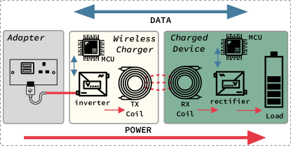
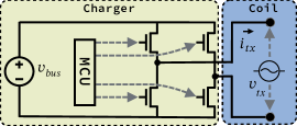
A Qi wireless charging system comprises three primary devices depicted in Figure 1: a power adapter, a wireless charger, and a charging device. The power adapter’s main function is to supply DC voltage to the wireless charger via a power cable, such as a USB cable. The wireless charger, also known as the power transmitter (TX device), utilizes an inverter to convert the DC voltage from the power adapter into AC voltage on the TX coil. The microcontroller unit (MCU) in the charger controls the amplitude and frequency of this AC voltage, generating a strong alternating magnetic field known as the power signal in wireless charging systems. The charged device, or power receiver (RX device), captures this magnetic field through the RX coil, inducing an AC voltage. The RX device’s rectifier then converts this AC voltage back into DC voltage and provides power to load.
One of the most significant distinctions between wireless and wired charging is
the absence of physical electrical connections to the RX device during charging.
A common vulnerability in wired charging is that electrical connections to a
charged device can inadvertently allow malicious actors to gain unauthorized
access to the charged device through the data wires in the charging
cable [13, 25, 20]. Wireless
charging effectively eliminates this direct data path introduced by physical
connections. Therefore, an important Security Characteristic (SC)
provided by wireless charging is:
Qi wireless charging also features robust in-band communication, where RX and TX devices exchange data by modulating and demodulating power signals using different schemes.
RX devices modulate power signals with Amplitude-Shift Keying (ASK) from the load side, while TX devices apply Frequency-Shift Keying (FSK) to modulate signals from the charger side.
Numerous techniques are specified to ensure communication robustness.
For instance, Qi wireless charging uses Biphase Mark Coding (BMC) for bit encoding, which is known for its resilience to interference.
Additionally, error detection bits and checksum bytes are incorporated to ensure data integrity.
The robust Qi communication is crucial for the Qi standards’ key
safety features, such as feedback charging control and foreign object detection,
ensuring a safe charging process.
Feedback Charging Control During charging, a power receiver
regularly sends Control Error (CE) packets to command the transmitter
to adjust the charging power. In response, the transmitter feeds the CE
value to a PID controller to update the controlling signal on the inverter. This
feedback control is essential to guarantee the charging power is
dynamically adjusted to meet the power receiver’s needs. Furthermore, when the
power receiver detects abnormal charging status or is fully charged, it sends the End Power Transfer (EPT) packet to command the transmitter to terminate the charging.
Therefore, the second security characteristic provided by wireless charging
is:
Foreign Object Detection
Qi standards define Foreign Object Detection (FOD) to avoid heating and damaging magnetic-field sensitive foreign objects exposed in the magnetic field, enhancing the charging safety.
The FOD can be performed before and during the
power transfer. Pre-power transfer is mandatory when the power receiver requests
a high charging power using the extended power protocol.
During this process, the power receiver sends a FOD packet containing the reference value of resonance properties to the transmitter.
The transmitter compares this reference value with the value measured by itself to determine whether a foreign object is present.
In-power transfer FOD is employed in both baseline and extended power protocols.
During charging, the power receiver must update the transmitter with the
Received Power (RP) packets. The power transmitter compares the
transmitted power measured by itself with the reported power received by the power receiver to
calculate the amount of unintended power transfer to foreign objects. If the
difference exceeds a predefined threshold, the charger identifies it as unsafe
and terminates the power transfer. Therefore, another security characteristic of
wireless charging is:
3 Threat Model and Attack Overviews
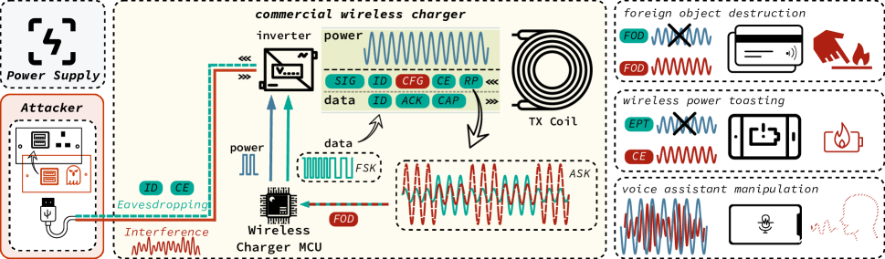
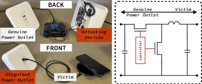
Our threat model and attack scenarios are depicted in Figure 2. We assume a commonly adopted threat model for charging attacks, where an adversary compromises the power adapter that supplies DC voltages to the wireless charging system. To achieve this, an attacker connects a disguised voltage manipulation device between the power adapter and wireless charger, inducing voltage fluctuations to manipulate the power signal via the EMI effect, enabling a series of attacks. We do not presuppose the necessity for attackers to interfere with data transmission lines in USB cables. The attacks are initiated when a victim unsuspectingly leaves a smartphone or metallic personal items near the charging area either for charging or non-charging purposes. The attacks listed below can invalidate all three security characteristics introduced in Section 2.
4 Wireless Charging System Security Analysis
To understand why and how attacks can be carried out through the power cable of a wireless charging system, two critical questions must be answered: \Circled1 How can interference impact a wireless charging system through its power cable, and in what ways? \Circled2 What detailed information regarding the status of a wireless charging system can be collected from the power cable?
To answer these questions, we conducted a comprehensive analysis of the wireless charging system depicted in Figure 3. In Section 4.1, we examine how the schemed voltage interference at the power adapter’s output propagates in the systems and impacts the transmitted power signal of the system. In Section 4.2, we explore how the workload behavior-induced signals propagate back to the power adapter’s output and impact the output voltage.
4.1 Adapter-to-Load Propagation
A regular wireless charging system follows electromagnetic compatibility and power electronics principles: ensuring that the noise from a power supply, a power adapter in this case, does not disrupt the system’s normal power conversion. However, the in-band communications employed in Qi wireless charging systems may encounter a different story. This section analyzes how an interference signal at the output of a power adapter affects the in-band communication, which is realized by modulating power signal transferred to the charging receiver via the couplings between the coils. We consider a scenario where the output voltage , as defined in Equation 1, of an interfered power adapter is composed of the nominal DC output voltage superimposed by a noise with an interference depth and frequency ,
| (1) |
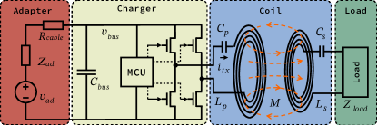
Because of large number of electronic components, including multiple non-linear components such as time-variant loads, analyzing the impact of noise on wireless charging power in such a complex wireless charging system is challenging. To perform a precise yet manageable analysis, we introduce rational simplifications based on electrical principles and the significance of components’ impacts. For this analysis, the workload is assumed to remain in a steady state, effectively modeled as a constant resistor . The system is segmented into three parts for sequential analysis of interference’s impacts. Part 1 (Figure 4) examines the impact of the changes of at the power adapter’s output on , the DC input of the inverter. Part 2 (Figure 5) explores how impacts the AC voltage across the resonant capacitor and TX coil at the output of the inverter. Part 3 (Figure 6) models the influence of the inverter’s output AC voltage on the current in the TX coil, which directly reflects the power signal’s property.
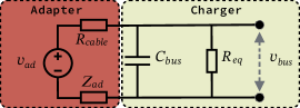
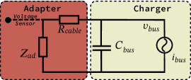
Part 1: Transfer function from the adapter to the charger The influence of power adapter output voltage on bus voltage can be analyzed based on the model in Figure 4. The bus voltage that drives the inverter is a function of the power adapter’s Thevenin equivalent output voltage source , Thevenin equivalent impedance , cable resistance , bus decoupling capacitor , and the equivalent load resistance . Given the interfered power adapter’s output voltage in Equation 1, the disrupted voltage can be derived from Figure 4 as in Equation 2 222In the equations presented in this paper, we use “” to represent the magnitude of a complex number .. In Equation 2, is composed of a periodic noise with frequency and amplitude superimposing on a DC component . is a voltage scaling factor dependent on the impedance of the model in Figure 4.
| (2) |
Part 2: Transfer function from the charger to the resonant tank The circuit of the inverter is shown in Figure 5. The inverter’s primary role is to convert into AC voltage across the resonant capacitor and TX coil, thereby creating the alternating magnetic field from the TX coil for power transmission. The inverter’s operation is controlled by the MCU through two parameters: the pulse width modulation (PWM) signal with duty cycle , and the power signal frequency, . The output of the inverter is a staircase waveform as shown in the Appendix B. It is fed into the resonance tank, and the TX coil. The harmonics of the staircase waveform outside of the bandwidth of the resonant tank are filtered out, leaving a sinusoidal signal with a frequency equal or close to the resonant frequency of the tank. As such, the output voltage of the inverter, , is derived in Equation 3, with the derivation process detailed in Appendix B. With steady-state workload, the primary factor influencing is , which determines the amplitude of .
| (3) |
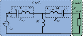
Part 3: Wireless Power Transfer The wireless power transfer section in Figure 3 can be modeled in Figure 6. The drives the TX coil, generating an alternating magnetic field and transferring power to the receiver. Based on the model, the current in the TX coil can be calculated in Equation4 333In this paper, the ”” symbol denotes the equivalent impedance of two parallel-connected components.. The equivalent impedance is a function of the load, coupling conditions, and power signal frequency. Given that the load, coupling conditions, and power signal frequency remain constant during this analysis, is the primary influential factor of the TX coil current.
| (4) |
Analysis Results From Equations 2,3, and 4, the TX coil current, , can be derived in Equation 5. From Equation 5, the schemed voltage noise on in Equation 1 impacts in the TX coil by modulating its amplitude. Because the is a complex number, a phase difference exists between and . The carrier signal amplitude is determined by duty cycle D. The modulation depth is proportional to the interference depth and the voltage scaling factor .
| (5) |
In Equation 2, can be approximately estimated using typical values of (5), (0.1), (50). For the interference frequencies at 1 kHz, 10 kHz, and 100 kHz, the estimated voltage scaling factor are 0.99, 0.95, and 0.30.
Conclusion Existing wireless charging systems effectively attenuate high-frequency interference but are less effective against low-frequency interference. Therefore, low-frequency interference from the power adapter can easily propagate to the TX coil and modulate the power signal’s amplitude with a modulation depth close to the interference depth.
4.2 Load-to-Adapter Propagation
An ideal power adapter is supposed to provide a constant DC voltage with minimal fluctuation, regardless of the workload behaviors. However, a real-world power adapter’s output is inevitably affected by workload behaviors mainly due to the limitations of switching regulator’s close-loop bandwidth and phase margin. This section analyzes specific workload behaviors that lead to measurable information leaks in the power adapter’s output based on the circuit model shown in Figure 7.
The impact of workload behavior on the power adapter’s output voltage noise can be analyzed by modeling the workload as an equivalent load current source in parallel with an equivalent impedance based on the Norton’s Theorem. Since this impedance is much bigger than that of , it is ignored in Figure 7. Based on the analysis in Section 4.1, can be derived using , , and per Equation 6. It is composed of a DC component and an AC current , which has a frequency of with an amplitude proportional to .
| (6) |
In Equation 6, is a function of time. It is almost constant within one switching period of the inverter but varies as the load current changes, which has much lower frequencies than that of the inverter. In a wireless charging system, we identify two workload behaviors that cause measurable signals on the output of the adapter. The first one is the AC current caused by the inverter’s switching behaviors at the frequency of . The other is the abrupt load-change behavior. These behaviors are analyzed individually to understand their specific impacts on the power adapter’s output voltage.
Inverter-switching Induced Signal According to Equation 6, an AC component of frequency is present in the bus current, where is the power signal frequency controlled by the charger’s MCU, typically around 140 kHz. The voltage changes at the output of the power adapter, denoted as , can be expressed as Equation 7. With typical values of (1A), (140 kHz), (10 m), (50 F), (0.1 ), and (70∘), the amplitude of can be estimated as 10 mV.
| (7) |
Load-change Induced Signal Based on Equation 6, a load change, in other words, a change in , also leads to the change of the load current in Figure 7. From Equation 7, the load change will lead to the voltage change at the output of the power adapter. Because of this, the load changes are detectable from . But as the power adapter tends to minimize with its high feedback control loop gain at low frequencies, the low-frequency spectrum of the is attenuated. Only the high-frequency spectrum of the due to the change of remain. As a result, for an abrupt load change, which is characterized with high high-frequency spectrum, the transient voltage deviated from the nominal voltage will be observed in the output voltage, and it will rapidly settle down to its steady state value due to the adapter’s close-loop feedback control. This results in a series of pulse signals including the load information. This effect can be approximated as the effect of a convolution filter . For a typical design, these pulses usually have small amplitudes, so they do not interfere with the normal operation of the power adapter.
Conclusion Voltage at the output of a power adapter contains the following workload behavior information signals: the timing of load change and the frequency at which the wireless power is transferred. Since has a small amplitude it does not affect the functionality of a power adapter. The signals in are also partially masked by other voltage noise, making them not immediately distinguishable in the raw data. However, understanding the generation and characteristics of these signals enables us to develop specialized signal processing techniques. These techniques can exploit the signals’ unique features to successfully extract the embedded information.
5 Preliminary Attack Vectors
Through comprehensive analysis, the two questions raised in Section 4 have been answered, yielding two essential insights concerning a wireless charging system:
This section showcases three practical attacks derived from our insights. We cover exploiting voice signal induction in charging smartphones (Section 5.1), injecting malicious Qi messages to alter charging control (Section 5.2), and recovering communication messages through voltage noise analysis (Section 5.3).
5.1 Attack Vector 1: Voice Injection
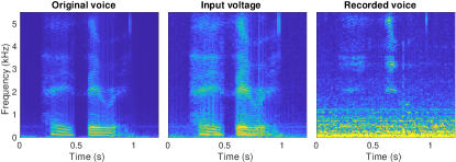
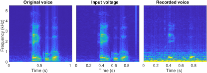
This section introduces our first practical attack vector, which is injecting voice signals into the charged smartphones. The most significant information in typical voice signals is in the frequency band below 10 kHz [15]. Therefore, according to Insight 1, when a voice signal is added to the power adapter’s output voltage, it can modulate the power signal at the TX coil with limited attenuation and distortions. A recent study [6] has demonstrated that an AM-modulated magnetic field can cause magnetic-induced sound (MIS) in the microphone circuits of modern smartphones through magnetic couplings. Thus, by adding voice signals to the power adapter’s output, we will be able to inject voice signals into the charged smartphones exposed to this intense magnetic field. To validate this sound-inducing mechanism, we conducted tests on an iPhone SE and a Pixel 3 XL with a Renesas P9242-R-EVK wireless charger. In these tests, we recorded the activation commands of these two smartphone assistants spoken by their owners. When the iPhone SE is under charging, the waveform of “Hey Siri” is added to the supply voltage, and a recording application on the smartphone is activated to capture any potential audio signals. Similarly, for the Pixel 3 XL, the test involves adding the waveform of “Hey Google” to the supply voltage and recording any resulting audio signals. The recording process takes place in a normal office environment with a reasonable level of background noise.
Figure 8 compares the spectrograms of the original voice signal, the adapter’s interfered output voltage signal, and the signal captured by the microphone during charging. It is evident from the spectrograms that some features of the original sound signal are recognizable in the MIS. However, the signal-to-noise ratio (SNR) of the MIS is affected by a couple of key factors. First, when the intensity of the resulting sound is weak, some patterns are overwhelmed by background noise. To counter this, we can increase the interference depth to enhance the SNR. Secondly, although the analysis in Section 4 demonstrates limited attenuation for low-frequency signals, different frequency components of the original voice signals are still subject to different attenuation. This unequal attenuation across the frequency band can distort the signal waveform and result in the loss of audio features.
A security implication of this attack vector is that an attacker may exploit this mechanism to inject voice commands and control the voice assistants in the charged smartphones. The voice assistants will likely recognize a considerable amount of features preserved in the MIS and execute the commands.
5.2 Attack Vector 2: Qi Message Injection
In this section, we explore the attack vector of injecting ASK-modulated Qi messages into the communication channels between RX and TX devices. During charging, the RX device modulates the power signal at a frequency of approximately 2 kHz. As per Insight 1, an interference signal around this frequency at the output of the power adapter can modulate the power signal with small attenuation. Therefore, it is feasible to inject synthesized ASK modulation signals, which strictly adhere to Qi communication protocols, into the output of the power adapter to deceive the TX device.
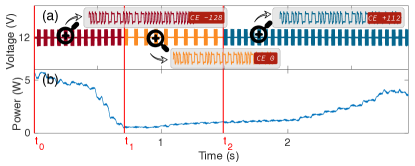
To demonstrate this capability, we used a Renesas P9242-R-EVK wireless charger to charge an iPhone SE. We injected fake CE packets into the power adapter’s output voltage to decive the charger. The charger adjusted its charging power as directed by the fake commands. The results are displayed in Figure 9, where the voltage trace shows three different CE messages, CE(-128), CE(0), and CE(+112), inserted at timestamps , , and , respectively. The power trace correlates the output power changes with the respective CE values, confirming that the charging power was manipulated as expected.
A security implication of this attack vector is that it provides the attacker with a communication channel to send malicious messages to chargers. Injecting interference at the ASK modulation frequency into the power adapter’s output can disrupt the genuine packets sent from RX devices and hijack the in-band communication. When the Qi communication is compromised, many charging safety mechanisms that heavily rely on this communication can be invalidated as well. An attacker can exploit this attack vector to induce hazardous charging processes that could severely damage the charged devices.
5.3 Attack Vector 3: Qi Message Eavesdropping
This section investigates the attack vector that enables an attacker to recover Qi messages using the voltage trace measured at the power adapter’s output. As introduced in Section 2, the RX and TX devices modulate the power signal using ASK and FSK modulations, which impact the power signal by shifting the load and altering the power signal frequency, respectively. According to Insight 2, the load power modulation will lead to measurable signals at the power adapter’s output. However, such information may not be directly visible in the measured raw traces due to the low intensity of these signals. Specialized signal processing techniques that target these signal features are necessary to extract this information. In the remaining part of this section, we present our methodologies for processing the signal to recover messages using ASK and FSK modulations. A voltage trace captured at the beginning of the charging initiation process between a Renesas P9242-R-EVK wireless charger and an iPhone SE will be used to demonstrate these methodologies.
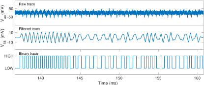
ASK Modulation Eavesdropping Analysis in Section 4.2 indicates that the effect of a load transition on the charged device on the power adapter’s output voltage can be represented by being filtered with a convolution filter . Therefore, to recover the waveform of the ASK modulation signal, we introduce the convolution kernel in Equation 8. is a triangle pulse smoothing filter designed to counteract the effects of the equivalent filter . The combined result forms a matched filter that detects transitions between LOW and HIGH at the frequency of . Given that BMC encoding schemes are used for bit encoding, a significant feature for distinguishing the transmission of ZERO and ONE is the phase shift pattern of the signal at frequency . Based on this characteristic, we further employ the filter in Equation 8 to enhance such phase shift patterns for the signals with frequency .
| (8) |
The effectiveness of these filters is demonstrated in Figure 10. While some pulses are visible in the raw trace, the modulating pattern is unclear. After filtering, we can effectively recover the signals with clear ASK modulation patterns, which can be further decoded into the binary HIGH-LOW sequence. For this specific example, we recover a SIG packet with the value 0x84 after decoding. Using the same technique, we can also recover other data packets sent by the power receiver, such as ID, CFG, FOD, GRQ, SRQ, RP, CE, etc.
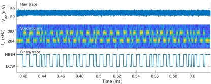
FSK Modulation Eavesdropping Analysis in Section 4.2 indicates that a weak signal at the frequency of can be measured at the power adapter’s output. With the TX device using FSK modulation to transmit data by altering the power signal frequency , an attacker can track the frequency changes to recover modulation signals. To extract these frequency-domain features, we perform a discrete Fourier transform (DFT) on the measured raw voltage trace and analyze the spectrogram. As the results in Figure 11 show, while no features are visible in the time domain trace, distinctive patterns exist in the frequency domain. When is around 140 kHz, frequency-switching patterns near 280 kHz are clear. In this case, we can decode the derived binary sequence to recover an ID packet, which discloses the charger’s identification.
This attack vector reveals several security concerns. Initially, it exposes that normal charging processes unintentionally leak charger and device models, allowing attackers to profile and target specific devices. Furthermore, combining eavesdropping on and injecting Qi messages grants attackers the ability to simulate a legitimate receiving device’s behavior. This deception could lead the charger to initiate power transfer under hazardous conditions, all achievable with mere access to the power adapter, indicating a significant threat to wireless charging security.
6 Practical Attacks Implementation
This section outlines conducting three practical attacks detailed in Section 5. It includes a setup for these attacks (Section 6.1), a method to manipulate voice assistants via injected commands (Section 6.2), a wireless power toasting attack causing charger-induced device damage (Section 6.3), and a foreign object destruction attack misleading the charger to damage non-targeted objects (Section 6.4).
6.1 Experimental Setup
In Figure 12a, we show a practical attacking setup that can be easily found in real-life scenarios. The attacker employs a disguised power port, which appears to be a regular USB-C port from the front but conceals a USB-C plug at the back. Behind this facade lies an attacker-controlled voltage manipulator connected between the power pins of the two USB-C connectors. As illustrated in Figure 12b, this manipulator alters the switching patterns of two MOSFETs to superimpose the manipulated AC voltage fluctuations onto the DC voltage.
In our experiment, we used the Analog Discovery 2 (AD2) as a controller to process the measured output and generate signals to control the injected noise waveform and intensity. For mass production, this prototype can be significantly miniaturized by substituting AD2 with a compact controller chip, akin to the size depicted in Appendix A. Installation of this device only requires simply plugging it into a COTS power adapter’s power port and replacing its functionality. Given the uniform function of power adapters to supply DC voltage, this method is universally applicable to all COTS power adapters. We tested Apple, Google, and Amazon power adapters to verify our ability to inject configurable voltage noise with specific and values. We show wireless chargers connected to this disguised power port are vulnerable to various attacks. The efficacy and practicality of VoltSchemer are validated through evaluations on 9 popular wireless chargers listed in Table 1, featuring a range of manufacturers and power ratings.
| ID. | Manufacturer | Model | Rated Power |
| 1 | KEYOMOX | B0835LGZ9B | 5W |
| 2 | Anker | A2503 | 10W |
| 3 | COCOEYE | Wi-II | 10W |
| 4 | FDGAO | B413 | 10W |
| 5 | Philips | DLP9035BC/27 | 10W |
| 6 | YOOTECH | F500 | 10W |
| 7 | Renesas | P9242-R-EVK | 15W |
| 8 | TOZO | W1 | 15W |
| 9 | WaiWaiBear | PAWCS11B | 15W |
6.2 Voice Assistant Manipulation
As discussed in Section 5.1, by interfering with the supply voltage of the wireless charger, voice signals can be induced in the microphone of a charged smartphone. This section shows how this method can be used to manipulate voice assistants, which are widely used in modern smartphones. To assess the practical impact of this voice assistant manipulation attack, we focus on two key aspects. First, we measure the maximum distance between the charger and the smartphone at which the attack remains effective. Additionally, to confirm the attack’s versatility in controlling voice assistants, we test it with a range of commonly used voice commands.
6.2.1 Attack Evaluations
We evaluated nine COTS wireless chargers, as listed in Table 1, using two smartphones: the iPhone SE and the Pixel 3 XL. The iPhone SE, manufactured by Apple, utilizes the iOS system and employs Siri as its voice assistant. The Pixel 3 XL, manufactured by Google, operates on the Android system and employs Google Assistant. Leveraging Attack Vector 3, the manufacturer information of the targeted smartphone can be procured from the eavesdropped ID packet sent by it.
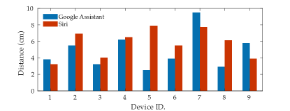
Evaluations of Attacking Distance Because Qi Wireless charging requires precise alignment between TX and RX coils for stable power transfer, the maximum measurable attacking distance is limited to 3 cm. Beyond this distance, the charging process is terminated. To facilitate evaluations of longer attack distances, we placed a Renesas P9221-R power receiver on the charging pad to keep the wireless charger running even when the smartphone is moved out of the charging range, ensuring consistent power transfer during the evaluation. We introduced interference using the voice assistant activation commands “Hey Siri” and “Hey Google” to target the voice assistants of the iPhone SE and Pixel 3 XL, respectively. The interference depth is fixed at 0.3, which is the minimal level sufficient to activate all voice assistants without disrupting power transfer. We measured the maximum distances at which voice assistants can be successfully activated by placing the smartphone at different distances from the charging pads.
The evaluation results in Figure 13 indicate that although successful attacks have different maximum attacking distances from 3 cm to 10 cm between the chargers and the smartphones for different wireless chargers, the maximum distance is not smaller than the 3 cm wireless charging range limited by the misalignment constraint in Qi standard, therefore, the voice assistant manipulation attacks can always be successfully conducted to the charged smartphones.
Evaluations of Voice Commands We evaluated six frequently used voice commands on the iPhone SE and Pixel 3 XL to assess the effectiveness of injecting different voice commands across various wireless chargers and smartphones. These commands are designed to prompt specific actions with the voice assistant, including activating the assistant, initiating a phone call, browsing a website, launching an app, using the speaker, and controlling the camera. The system’s resilience to a voice assistant manipulation attack depends on many factors, including the electrical characteristics of the system, the features of the voice signals, and the algorithms of the voice assistants. To launch a successful attack on a more resilient system, a higher interference depth is required to induce a stronger voice signal. Meanwhile, an excessively high interference depth may intermittently disrupt the charging process and compromise the stealthiness of the attack. For instance, we observed that intermittent charging interruptions start occurring when exceeds 0.35 and become more frequent when surpasses 0.5. Therefore, our evaluations aim to identify the minimum interference depth required for successful command injection. Lower means more efficient and stealthier attacks. We increased the interference depth by a 0.005 step from 0 to measure this threshold precisely.
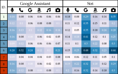
: Hey Siri/Google, \faPhone: Call Alice, \faGoogle: Go to google.com,
\faAmazon: Open Amazon, \faMusic: Play music, \faCamera: Take a selfie
The results in Figure 14 demonstrate how effective this attack is on various devices and voice commands. 105 of 108 voice commands can be successfully injected at interference levels lower than 0.35. Only 3 of 108 injections require an interference depth between 0.35 and 5. This shows the efficacy and feasibility of our voice assistant manipulation attacks.
6.3 Wireless Power Toasting
As demonstrated in Section 5.2, injecting interference with ASK modulation patterns into the supply voltage enables an attacker to manipulate the charging control. This section illustrates how this capability can be used to launch a wireless power toasting attack, potentially damaging the charged smartphones through overcharging and overheating. Vendor documentation indicates that modern smartphones typically incorporate multiple techniques to mitigate risks associated with overcharging and overheating [8, 7]. Therefore, a strategic approach is necessary to circumvent these protection measures. Smartphones typically adopt three protection measures: P1 - terminating charging, P2 - shutting down all apps and disabling user interaction, and P3 - initiating an emergency shutdown. While P2 and P3 focus on reducing heat generation within the smartphone itself, P1 poses a direct challenge to the attack. This protection involves two actions: commanding the charger to stop power transmission by sending an EPT message and deactivating the smartphone’s power receiving module. The charger may cease power transmission either immediately upon receiving an EPT message or, alternatively, due to a loss of communication if it fails to receive regular CE and RP packets from the smartphone.
Thus, besides increasing charging power with CE packets, we developed a strategy fulfilling two additional critical requirements to execute the wireless power toasting attack: \Circled1 Inject interference to disrupt legitimate Qi messages from the smartphone to prevent charging termination triggered by EPT packets. \Circled2 Continuously inject CE and RP packets regularly to sustain the Qi communication with a charger, even after the smartphone’s power receiving module is deactivated.
6.3.1 Attack Evaluations
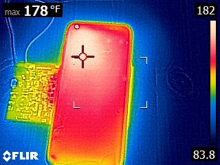
To evaluate whether the wireless power-toasting attack can succeed even with the protection measures employed in smartphones, we conducted experiments using a Samsung Galaxy S8 smartphone 444A different smartphone was used for potentially destructive experiments.. Upon injecting CE packets to increase power, the temperature rapidly rose. Shortly after, the phone tried to halt power transfer (P1) by transmitting EPT packets due to overheating, but the voltage interference introduced by our voltage manipulator corrupted these, making the charger unresponsive. Misled by false CE and RP packets, the charger kept transferring power, further raising the temperature. The phone further activated more protective measures: closing apps and limiting user interaction (P2) at 126 F∘ and initiating emergency shutdown (P3) at 170 F∘. Still, power transfer continued, maintaining a dangerously high temperature, stabilizing at 178 F∘ as per Figure 15. The actual core temperature inside the phone often surpasses the surface temperature.
In experiments conducted on all evaluated chargers, we recorded the maximum charging power and highest temperature each charger could induce on a smartphone, and checked the activation of three thermal protection measures, P1, P2, and P3. Using a thermal camera and battery health monitor app, we monitored the surface and core battery temperatures on the phone. The measured core temperature using the app stopped at 131 F∘ due to the activation of P2, although the actual temperature continuously increased far beyond that. The recorded surface temperature with the thermal camera reaches as high as 179 F∘. As detailed in the results from Table 2, our results reveal concerning findings. All compromised chargers pushed the phone’s temperature beyond its specified working temperature (95F∘). High-power chargers caused even more thermal stress. All tested chargers, when compromised, can trigger the power receiving termination protection measure. High power chargers (~10W) can force the phone into the second thermal protection mode, restricting user interactions. In the worst scenarios, ~15W chargers can force smartphones to shutdown due to excessive heat. Such persistent overheating attack presents a much higher risk than typical phone-generated overheating, potentially causing battery failure or explosion.
| ID. | P1 | P2 | P3 | Core Temp (∘F) | Surf Temp (∘F) | PWR (W) |
| 1 | ✓ | ✓ | ✗ | 131+ | 124 | 9 |
| 2 | ✓ | ✗ | ✗ | 109.4 | 109 | 5.2 |
| 3 | ✓ | ✗ | ✗ | 125.42 | 118 | 7.3 |
| 4 | ✓ | ✓ | ✗ | 131+ | 125 | 9.3 |
| 5 | ✓ | ✓ | ✗ | 131+ | 126 | 7.6 |
| 6 | ✓ | ✓ | ✗ | 131+ | 126 | 9.2 |
| 7 | ✓ | ✓ | ✓ | 131+ | 179 | 18 |
| 8 | ✓ | ✓ | ✓ | 131+ | 173 | 17 |
| 9 | ✓ | ✓ | ✗ | 131+ | 149 | 13.2 |
6.4 Foreign Object Destruction
Leveraging Attack Vector 2 and Attack Vector 3, an attacker can inject and receive Qi communication packets, thus enabling interactive communication with the wireless charger and mimicking a legitimate RX device. This capability allows an attacker to manipulate the charger into transferring power even without actual RX devices present. This section demonstrates the foreign object destruction attack, where the charger is controlled to damage foreign objects by transferring power to them and causing excessively high temperatures.
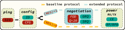
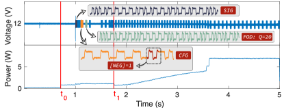
Through an in-depth analysis of the Qi wireless charging protocol, we identified critical steps to initiate power transfer to foreign objects. The procedure is detailed in Figure 16a, and its practical implementation is demonstrated in Figure 16b, which shows the interfered voltage and output power traces during the manipulation of a charger to transmit power to a metal foil. The process involves three key stages: ping, configuration, and negotiation. In the ping stage, starting at , the charger applies a power signal and awaits a response. We must respond with a SIG packet within the required timeframe to proceed to the configuration stage. Here, a fabricated device ID is sent to the charger, and the power protocol is selected by setting the NEG bit in the CFG packet. To ensure higher charging power, the extended protocol is selected by setting NEG to 1 and proceeding to the negotiation stage. Otherwise, the charger defaults to the baseline protocol with a maximum charging power of 5W. During negotiation, a key step is injecting a FOD packet with a low reference Q-factor. This strategy exploits the charger’s FOD check mechanism, which compares the measured Q-factor against the reference value provided by the RX device. By setting a low threshold, the charger is misled into passing the FOD check and issuing an ACK response. Subsequently, we request further details from the charger, such as its ID and charging capabilities, by injecting general request (GRQ) and specific request (SRQ) packets. After negotiation, the charger is successfully directed to the power transfer stage with the extended protocol at . At this point, the power transfer rate is adjusted and kept high through the injection of tailored CE and RP packets, heating up and potentially damaging foreign objects.
6.4.1 Attack Evaluations
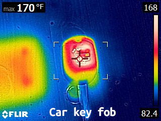
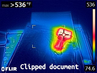
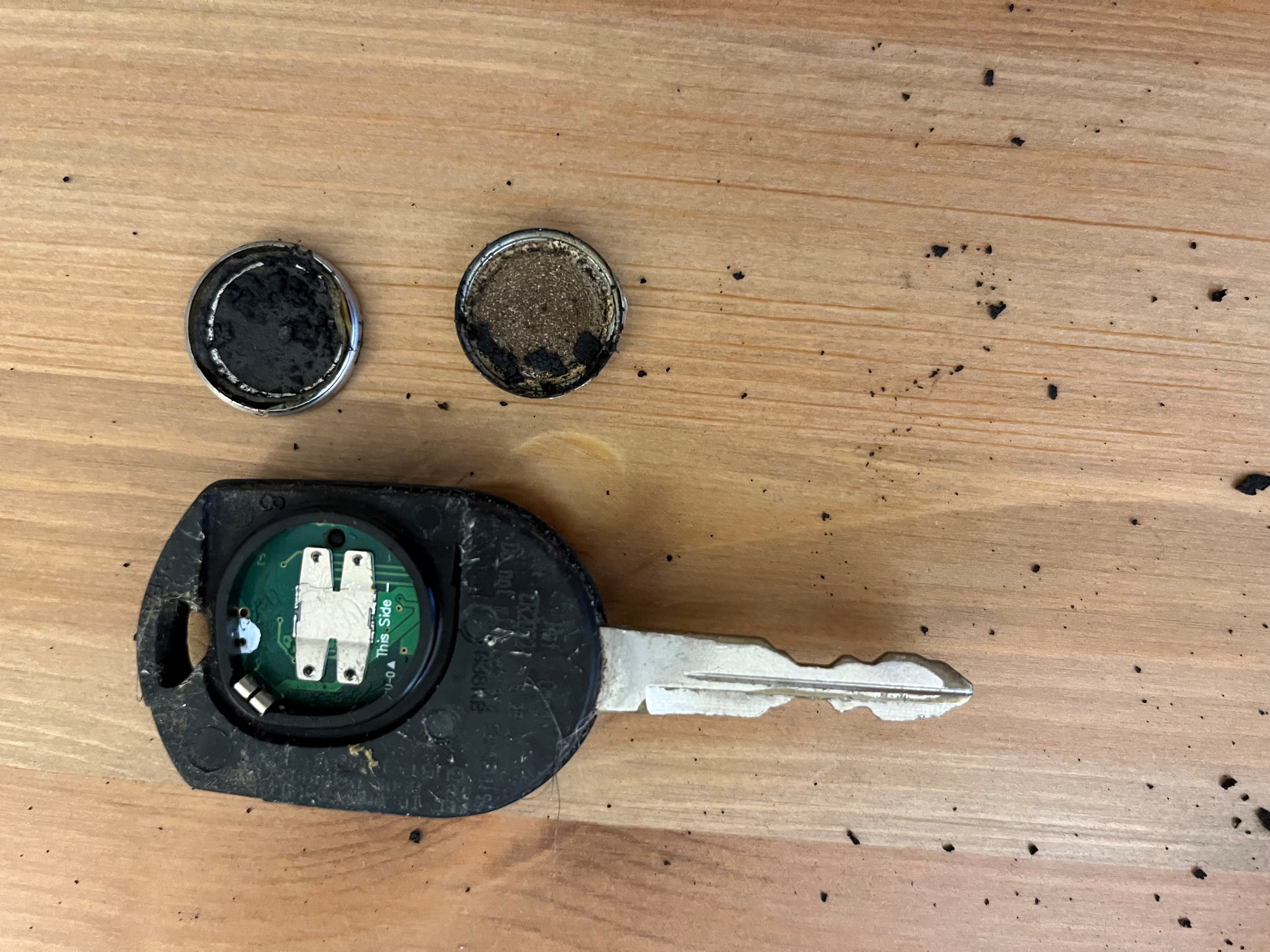
We carried out the attacks on six common personal items, initiating power transfer and maintaining the maximum charging power until visible damage occurs or the maximum temperature is sustained for two hours. Our evaluations, as shown in Figure 17, reveal some concerning outcomes:
Key Fob: Upon initiating power transfer to a car key fob placed on the
charging pad, the battery inside reached a critical temperature. As a result,
the key fob didn’t merely overheat. Instead, it detonated and caused the
disintegration of the device in an explosive display.
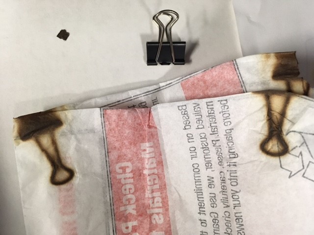
Paper Clips: The temperature exceeded 536°F when heated, which can
potentially damage or destroy important documents affixed by these clips.
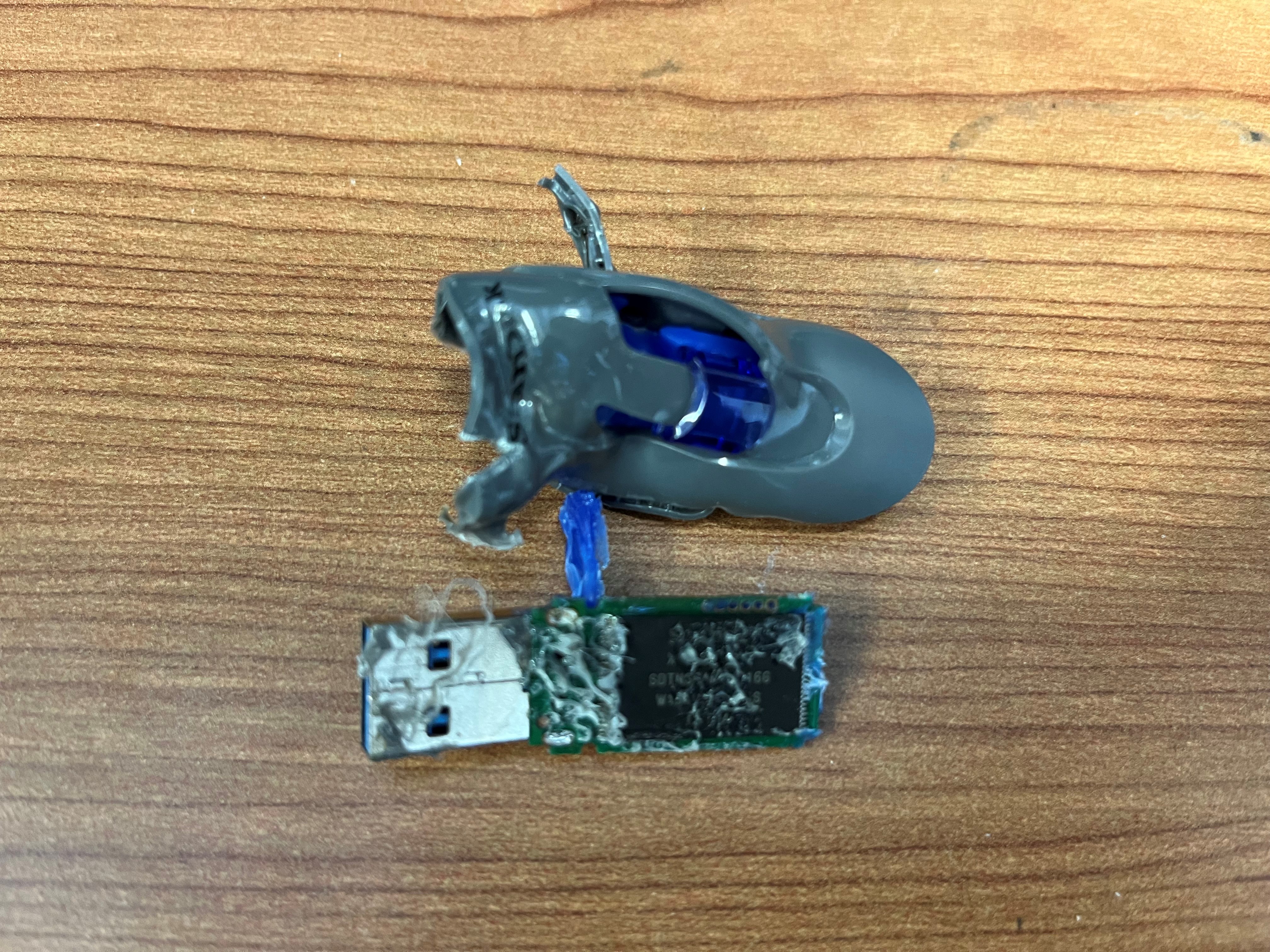
USB Drive: The high temperature caused significant damage to the USB
drive and the memory chip, making the contained data unrecoverable.
Solid-State Drive (SSD): SSD is commonly found on laptops and can be
accidentally placed on the charging pad. We find that our attack can overheat
the controller and flash of SSD into unrecoverable states thus rendering
it to suffer data loss.555The SSD is expected to be more susceptible to high temperature when actively operating in a laptop because the maximum operating temperature specified for SSD is 149 ∘F.
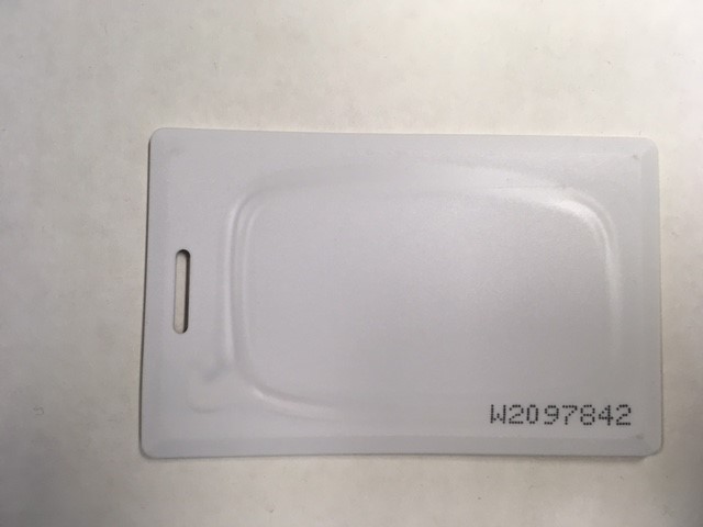
Passport and NFC Cards: Personal identification documents often contain RFID tags as identification chips. Similarly, NFC cards
are often used as security tokens for verification. However, when these items are
accidentally left on the charging pad, the strong magnetic field generated by
the charger can immediately destroy these identification tokens.
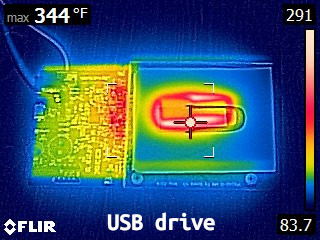
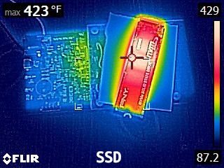
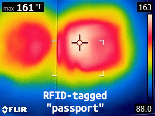
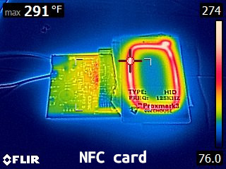
We tested each charger for its destructive potential on the objects and measured the maximum charging power achievable when transferring power to a paper clip. The results listed in Table 3 show that all chargers can readily destroy RFID tags and NFC cards. The damage potential increases with the increased charging power. Even if some chargers do not directly damage certain objects, they can generate temperatures exceeding the safe limits for components like SSDs and USB drives, thereby causing permanent data loss.
| ID. | SSD | USB | KFB | NFC | RFID | PWR (W) |
| 1 | ✗ | ✗ | ✗ | ✓ | ✓ | 6 |
| 2 | ✗ | ✗ | ✗ | ✓ | ✓ | 5 |
| 3 | ✗ | ✗ | ✗ | ✓ | ✓ | 7.9 |
| 4 | ✗ | ✗ | ✓ | ✓ | ✓ | 9.3 |
| 5 | ✗ | ✗ | ✗ | ✓ | ✓ | 5.5 |
| 6 | ✗ | ✗ | ✓ | ✓ | ✓ | 9.2 |
| 7 | ✓ | ✓ | ✓ | ✓ | ✓ | 19 |
| 8 | ✓ | ✓ | ✓ | ✓ | ✓ | 18 |
| 9 | ✓ | ✓ | ✓ | ✓ | ✓ | 15 |
7 Discussion
In this section, we discuss the practicality and stealthiness of our attacks, compare our work with state-of-the-art research, and provide insights for diverse charging protocols. We also propose countermeasures to mitigate the risks of our attacks.
7.1 Comparison With Prior Works
To clarify the uniqueness of VoltSchemer, we conducted a detailed comparison with state-of-the-art wireless charger manipulation attacks [27, 6]. This comparative analysis, outlined in Table 4, focuses on the practical implementation aspects and the specific attack capabilities of these methods. In-depth discussions of these two aspects are provided in the remaining part of this section.
| Work | Practicality | Attacks | |||||
| \faWrench | \faExchange | \faEyeSlash | \faCartArrowDown | \faMicrophone | \faBattery[4] | \faChainBroken | |
| Qi Hijacking[27] | ✓ | ✓ | ✗ | ✗ | ✗ | ✓ | ✗ |
| Wormheart[6] | ✗ | ✗ | ✓ | ✗ | ✓ | ✗ | ✗ |
| Parasite [6] | ✓ | ✓ | ✗ | ✗ | ✓ | ✗ | ✗ |
| VoltSchemer | ✓ | ✓ | ✓ | ✓ | ✓ | ✓ | ✓ |
: Feasible installation, \faExchange: Versatility, \faEyeSlash: Stealthy modification, \faCartArrowDown: COTS evaluations, \faMicrophone: Voice assistant manipulation, \faBattery[4]: Charging manipulation, \faChainBroken: Foreign object destruction
Comparison of Implementation Practicality Figure 18 shows three different methods of wireless charger manipulation attacks: \Circled1 adversarial coil plate insertion, \Circled2 charging pad alternation, and \Circled3 power supply interposing.
The “Wormheart” attack [6] involves installing customized firmware in the charger, usually by modifying or replacing its MCU. However, as detailed in Appendix A, the MCU’s small size and dense integration on the charger board make malware installation infeasible. Moreover, this method’s versatility is limited as each distinct charging system necessitates a uniquely customized malware. The work by Wu et al. [27] and the “Parasite” voice assistant manipulation attack [6] both require inserting adversarial coils over the genuine wireless charger. Because users must place devices on the adversarial coil for each charging session, such frequent interaction increases the chance of discerning the anomalies, thereby undermining the attack’s stealthiness. Our VoltSchemer attacks employ IEMI on the power supply to control the charger, requiring only an intermediary device connection to the power adapter. While both VoltSchemer and adversarial coil methods involve adding a device, ours is more covert. Primarily, our method capitalizes on the infrequent inspection of power adapters and charging cables, in line with wireless charging’s core principle of minimal wire interaction. Furthermore, replicating a standard power port is more viable, owing to the common, simple design of regular outlets. In addition to these advantages, our approach’s versatility is demonstrated by testing on 9 different wireless chargers, including COTS devices, a significant expansion from previous works [27, 6] that only assesses a single evaluation board charger.

Comparison of Attack Capability Our research outweighs state-of-the-art works in both the breadth and depth of evaluations concerning three attack capabilities. The voice assistant manipulation attack in [6] is narrowly focused on a single custom-built wireless charger, only testing the activation of voice assistants. Our VoltSchemer approach broadens this scope significantly by evaluating 9 varied COTS wireless chargers with 6 different common voice commands. This not only proves the versatility of VoltSchemer across various hardware configurations but also uncovers deeper insights into the security risks associated with voice assistant manipulation attacks, highlighting the importance of comprehensive security measures in wireless charging technologies. Wu et al.’s work [27] demonstrates the impact of injected CE packets on charging power, but didn’t progress to practical attacks. Our VoltSchemer evaluations reveal that altering CE packets alone is ineffective against modern smartphones’ overcharging protections. Leveraging an in-depth understanding of Qi wireless charging protocols, we develop a practical power toasting attack with more skillfully controlled implementations. Our tests confirm that VoltSchemer can circumvent three protective measures, causing dangerously high temperatures in smartphones, thereby demonstrating a deeper insight into the attack’s causes and impacts. Moreover, we introduce an unprecedented attack scenario in existing research. Our extensive evaluations show that VoltSchemer can manipulate wireless chargers to breach the protections of Qi standard, causing damage to metallic foreign objects, showcasing the potential for significant property loss and safety hazards.
7.2 Insights for Diverse Charging Protocols
The core issue facilitating our attacks is the insufficient noise suppression in certain frequency bands, leaving systems vulnerable to interference even if they meet existing EMC/EMI standards. This gap makes all wireless charging technologies potentially vulnerable to interference-based attacks, particularly high-power systems like electric vehicle (EV) wireless charging. Despite the nascent stage of EV wireless charging standards and efforts to incorporate safety measures, our research demonstrates the significant risks of system compromise, including property damage and threats to human safety. Our findings reveal the urgent need for improved protective measures against such IEMI interference, pointing to the critical importance of safeguarding wireless charging infrastructure from these sophisticated threats.
7.3 Countermeasures
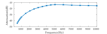
A practical countermeasure to our attacks involves integrating noise suppression components, such as additional DC/DC converters, to remove noise in the input voltage. To validate this approach, we connect a DC/DC converter to the input power port of a Renesas P9242 wireless charger and assess the attenuation of injected noise. By injecting voltage noises across frequencies ranging from 500 Hz to 10kHz and measuring the voltages both before and after the DC/DC converter, we quantify the attenuation level. As Figure 19 illustrates, the converter achieves a minimum noise reduction of 15 dB, with more substantial attenuation at lower frequencies. This additional converter effectively mitigates all three attacks. However, this solution comes with trade-offs. For instance, it increases the charger’s cost, size, weight, and failure rate. Moreover, the additional components also increase the power consumption and pose more thermal stress challenges.
An alternative countermeasure involves real-time monitoring the voltage waveform DC bus. If the charger detects abnormal noises, which may indicate IEMI injection, it can respond by triggering alarms or shutting down to avoid further damage. However, the cost implications of implementing this mitigation may also pose a challenge for low-cost devices.
8 Related Work
8.1 Attacks during Charging
Smart devices often exchange information with chargers during the charging processes via USB cables, which also help to transfer files or install applications. The charging process can be exploited for eavesdropping, as changes in power consumption can be detected through the charging channel.
With Wired Charging, studies have shown that malicious charging cables can be used to control mobile devices and install malicious applications [13, 17, 22]. Certain techniques can bypass the port lock mechanism, inject voice commands [25], or inject touch events onto touchscreens [11]. There are also techniques to procure sensitive information from the charged devices, like screenlock passwords [20, 4], browsing activities [28], and installed applications [3]. Wireless charging, while popular due to its cordless design, presents new challenges. It has been demonstrated that wireless charging can also be vulnerable to side channel attacks [12, 16]. Vulnerabilities in the Qi wireless charging protocol have been exposed, which can be exploited to inject malicious charging commands and eavesdrop using an externally placed coil [26, 27]. Further improvements in eavesdropping attacks have been made by measuring the power consumption of the wireless charger [14]. There are also techniques that use a customized wireless charging coil to induce magnetic interference and inject voice commands [6, 5].
8.2 Inaudible Voice Injection Attacks
There are many well-known attacks on microphones to manipulate the sensed voice on smart devices and inject malicious voice commands. Among these voice injection attacks, two main categories of attacks are often discussed.
Indistinguishable Voice Injection generates malicious audio that can be interpreted by speech recognition systems but not by humans. This attack is demonstrated by Vaidya et al. [23] and Carlini et al. [2], further improved by Yuan et al. [29] by embedding voice commands into songs. Sch"onherr et al. [19] and Abdullah et al. [1] further refined the attack for broader use and practicality. Although researchers use several means to generate better malicious audio, this type of attack still relies on the fact that an audible voice carrier is needed, which is a hard requirement.
Inaudible Voice Injection produces voice signals only detectable by microphones. Wang et al. [30], Sugawara[21], and Roy et al. [18] proposed using ultrasonic frequency carrier signals, laser signals, and ultrasound speaker arrays for such attacks. Ji et al. [10] used an implanted capacitor for this purpose. Dai et al. [6, 5] and Wang et al. [25] demonstrated this attack can be executed via a wireless charger or a charging cable.
9 Ethical Considerations
Responsible Disclosure We have contacted vendors to report the identified vulnerabilities, including NXP, Renesas, Infineon, ST, Wireless Power Consortium, etc. Countermeasures that can be employed by hardware vendors are under discussion and will be further disclosed in the future.
IRB Approval The University of Florida Institutional Review Boards have approved this research. The IRB approval number is ET00020284.
Impact on Power Grid Integrity Following reviewers’ recommendations, we evaluated our experiment’s potential impact on the power grid’s integrity. We can ascertain that the impact is negligible. This is largely due to the power adapter’s noise-isolation design and the low-power interference signals used. However, future research involving IEMI should proactively and thoroughly assess the potential impact on the integrity of power grid, particularly in scenarios where interference is injected closer to the grid or with higher intensity.
Safety Measures In our study, certain experiments posed risks of battery fires and explosions. To address these concerns, we set up a controlled environment to ensure safety. The experiments took place in a clean, non-flammable area, equipped with adequate ventilation to prevent the accumulation of hazardous gases. Protective barriers were installed around the Device Under Test (DUT) to contain any fragments from potential explosions. Moreover, we ensured the availability and accessibility of specialized fire extinguishers, specifically designed for handling electrical and chemical fires, as a crucial safety measure.
10 Conclusion
In this paper, we identified vulnerabilities of wireless chargers that enable the implementation of VoltSchemer, a set of powerful and practical active attacks against COTS wireless chargers. Exploiting voltage interference on the power adapters’ output voltage, VoltSchemer can manipulate the chargers to perform malicious activities like injecting inaudible voice commands to control voice assistants, overheating the charged devices, and destroying metallic foreign objects. Comprehensive evaluations of top-selling wireless chargers confirm the effectiveness and practicality of VoltSchemer attacks.
Acknowledgement
We appreciate the reviewers and the shepherd for their insightful comments and suggestions. This work was supported partially by the National Science Foundation under award numbers 1818500 and 1916175, and partially by the gift donation from Intel.
References
- [1] Hadi Abdullah, Washington Garcia, Christian Peeters, Patrick Traynor, Kevin Butler, and Joseph Wilson. Practical Hidden Voice Attacks against Speech and Speaker Recognition Systems. In Network and Distributed System Security Symposium (NDSS), 2019.
- [2] Nicholas Carlini, Pratyush Mishra, Tavish Vaidya, Yuankai Zhang, Micah Sherr, Clay Shields, David Wagner, and Wenchao Zhou. Hidden voice commands. In Proceedings of the 25th USENIX Conference on Security Symposium, SEC’16, page 513–530, USA, 2016. USENIX Association.
- [3] Yimin Chen, Xiaocong Jin, Jingchao Sun, Rui Zhang, and Yanchao Zhang. Powerful: Mobile app fingerprinting via power analysis. In IEEE INFOCOM 2017 - IEEE Conference on Computer Communications, pages 1–9, 2017.
- [4] Patrick Cronin, Xing Gao, Chengmo Yang, and Haining Wang. Charger-Surfing: Exploiting a power line Side-Channel for smartphone information leakage. In 30th USENIX Security Symposium (USENIX Security 21), pages 681–698, 2021.
- [5] Donghui Dai, Zhenlin An, and Lei Yang. Inducing wireless chargers to voice out. In Proceedings of the 28th Annual International Conference on Mobile Computing And Networking, MobiCom ’22, page 808–810, New York, NY, USA, 2022. Association for Computing Machinery.
- [6] Donghui Dai, Zhenlin An, and Lei Yang. Inducing wireless chargers to voice out for inaudible command attacks. In 2023 IEEE Symposium on Security and Privacy (SP), pages 503–520. IEEE Computer Society, 2022.
- [7] Google. Help keep your pixel phone from feeling too warm or hot. https://support.google.com/pixelphone/answer/3333708?hl=en. Access date:2023-08-29.
- [8] Apple Inc. If your iphone or ipad gets too hot or too cold. https://support.apple.com/en-us/HT201678. Access date:2023-08-29.
- [9] Fortune Business Insights. Wireless charging market size, share & covid-19 impact analysis, by application (commercial charging station and home charging unit), by technology (inductive, resonant, radio frequency, and others), by industry vertical (consumer electronics, automotive, industrial, healthcare, and aerospace & defense), and regional forecast, 2023-2030. https://www.fortunebusinessinsights.com/wireless-charging-market-105183, May 2023.
- [10] Xiaoyu Ji, Juchuan Zhang, Shui Jiang, Jishen Li, and Wenyuan Xu. Capspeaker: Injecting voices to microphones via capacitors. In Proceedings of the 2021 ACM SIGSAC Conference on Computer and Communications Security, CCS ’21, page 1915–1929, New York, NY, USA, 2021. Association for Computing Machinery.
- [11] Yan Jiang, Xiaoyu Ji, Kai Wang, Chen Yan, Richard Mitev, Ahmad-Reza Sadeghi, and Wenyuan Xu. Wight: Wired ghost touch attack on capacitive touchscreens. In 2022 IEEE Symposium on Security and Privacy (SP), pages 1537–1537. IEEE Computer Society, 2022.
- [12] Alexander S. La Cour, Khurram K. Afridi, and G. Edward Suh. Wireless charging power side-channel attacks. In Proceedings of the 2021 ACM SIGSAC Conference on Computer and Communications Security, CCS ’21, page 651–665, New York, NY, USA, 2021. Association for Computing Machinery.
- [13] Billy Lau, Yeongjin Jang, Chengyu Song, Tielei Wang, Pak Ho Chung, and Paul Royal. Mactans: Injecting malware into ios devices via malicious chargers. Black Hat USA, 92, 2013.
- [14] Jianwei Liu, Xiang Zou, Leqi Zhao, Yusheng Tao, Sideng Hu, Jinsong Han, and Kui Ren. Privacy leakage in wireless charging. IEEE Transactions on Dependable and Secure Computing, pages 1–1, 2022.
- [15] Brian B Monson, Eric J Hunter, Andrew J Lotto, and Brad H Story. The perceptual significance of high-frequency energy in the human voice. Frontiers in psychology, 5:587, 2014.
- [16] T. Ni, X. Zhang, C. Zuo, J. Li, Z. Yan, W. Wang, W. Xu, X. Luo, and Q. Zhao. Uncovering user interactions on smartphones via contactless wireless charging side channels. In 2023 2023 IEEE Symposium on Security and Privacy (SP) (SP), pages 3399–3415, Los Alamitos, CA, USA, may 2023. IEEE Computer Society.
- [17] Karsten Nohl and Jakob Lell. Badusb-on accessories that turn evil. Black Hat USA, 1(9):1–22, 2014.
- [18] Nirupam Roy, Sheng Shen, Haitham Hassanieh, and Romit Roy Choudhury. Inaudible voice commands: The long-range attack and defense. In Proceedings of the 15th USENIX Conference on Networked Systems Design and Implementation, NSDI’18, page 547–560, USA, 2018. USENIX Association.
- [19] Lea Schönherr, Katharina Kohls, Steffen Zeiler, ThorstenHolz, and Dorothea Kolossa. Adversarial attacks against automatic speech recognition systems via psychoacoustic hiding. In Network and Distributed System Security Symposium (NDSS), 2019.
- [20] Tadashi Shiroma, Yasuhiko Nishio, and Hiroyuki Inoue. A threat to mobile devices from spoofing public usb charging stations. In 2017 IEEE International Conference on Consumer Electronics (ICCE), pages 88–89, 2017.
- [21] Takeshi Sugawara, Benjamin Cyr, Sara Rampazzi, Daniel Genkin, and Kevin Fu. Light commands: Laser-based audio injection attacks on voice-controllable systems. In 29th USENIX Security Symposium (USENIX Security 20), pages 2631–2648, 2020.
- [22] O.MG Team. O.mg. https://o.mg.lol/.
- [23] Tavish Vaidya, Yuankai Zhang, Micah Sherr, and Clay Shields. Cocaine noodles: Exploiting the gap between human and machine speech recognition. In Proceedings of the 9th USENIX Conference on Offensive Technologies, WOOT’15, page 16, USA, 2015. USENIX Association.
- [24] Dries Van Wageningen and Toine Staring. The qi wireless power standard. In Proceedings of 14th International Power Electronics and Motion Control Conference EPE-PEMC 2010, pages S15–25. IEEE, 2010.
- [25] Yuanda Wang, Hanqing Guo, and Qiben Yan. Ghosttalk: Interactive attack on smartphone voice system through power line. In Network and Distributed Systems Security (NDSS) Symposium, 2022.
- [26] Yi Wu, Zhuohang Li, Nicholas Van Nostrand, and Jian Liu. Security and privacy in the age of cordless power world: Poster abstract. In Proceedings of the 18th Conference on Embedded Networked Sensor Systems, SenSys ’20, page 717–718, New York, NY, USA, 2020. Association for Computing Machinery.
- [27] Yi Wu, Zhuohang Li, Nicholas Van Nostrand, and Jian Liu. Time to rethink the design of qi standard? security and privacy vulnerability analysis of qi wireless charging. In Annual Computer Security Applications Conference, pages 916–929, 2021.
- [28] Qing Yang, Paolo Gasti, Gang Zhou, Aydin Farajidavar, and Kiran S. Balagani. On inferring browsing activity on smartphones via usb power analysis side-channel. IEEE Transactions on Information Forensics and Security, 12(5):1056–1066, 2017.
- [29] Xuejing Yuan, Yuxuan Chen, Yue Zhao, Yunhui Long, Xiaokang Liu, Kai Chen, Shengzhi Zhang, Heqing Huang, XiaoFeng Wang, and Carl A. Gunter. Commandersong: A systematic approach for practical adversarial voice recognition. In Proceedings of the 27th USENIX Conference on Security Symposium, SEC’18, page 49–64, USA, 2018. USENIX Association.
- [30] Guoming Zhang, Chen Yan, Xiaoyu Ji, Tianchen Zhang, Taimin Zhang, and Wenyuan Xu. Dolphinattack: Inaudible voice commands. In Proceedings of the 2017 ACM SIGSAC Conference on Computer and Communications Security, CCS ’17, page 103–117, New York, NY, USA, 2017. Association for Computing Machinery.
Appendix A Attacking Practicality Discussion
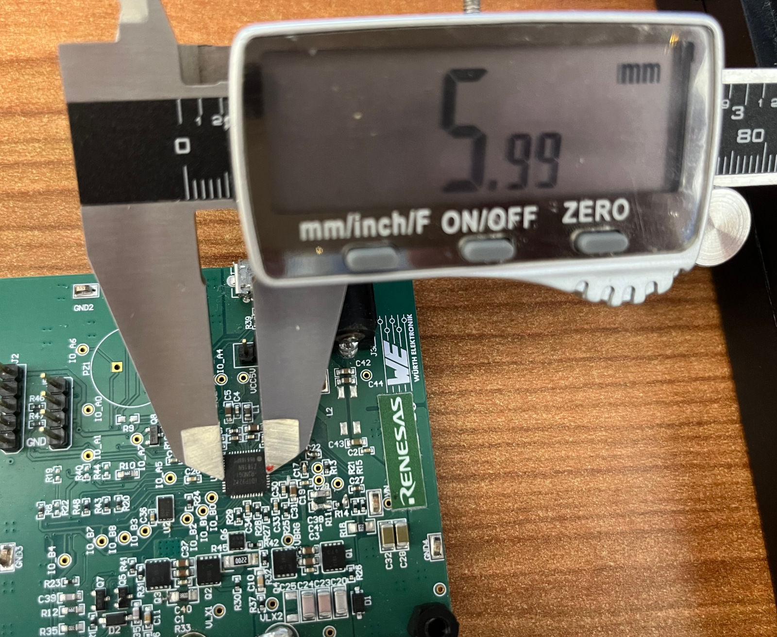
Figure 20 shows a microcontroller chip in a wireless charger. Due to its compact size and high level of integration on the board, malicious charging pad modifications requiring chip replacement are difficult to perform. This feature limits the practicality of the “Wormheart” attack.
Despite their small size, such chips are capable of performing complex computations, including processing voltage traces, decoding Qi messages, and generating control signals for power signal modulation. Thus, if mass production is needed, the size of our prototype VoltSchemer can be significantly reduced by substituting the AD2 with a chip at this scale.
Appendix B Inverter Output Voltage
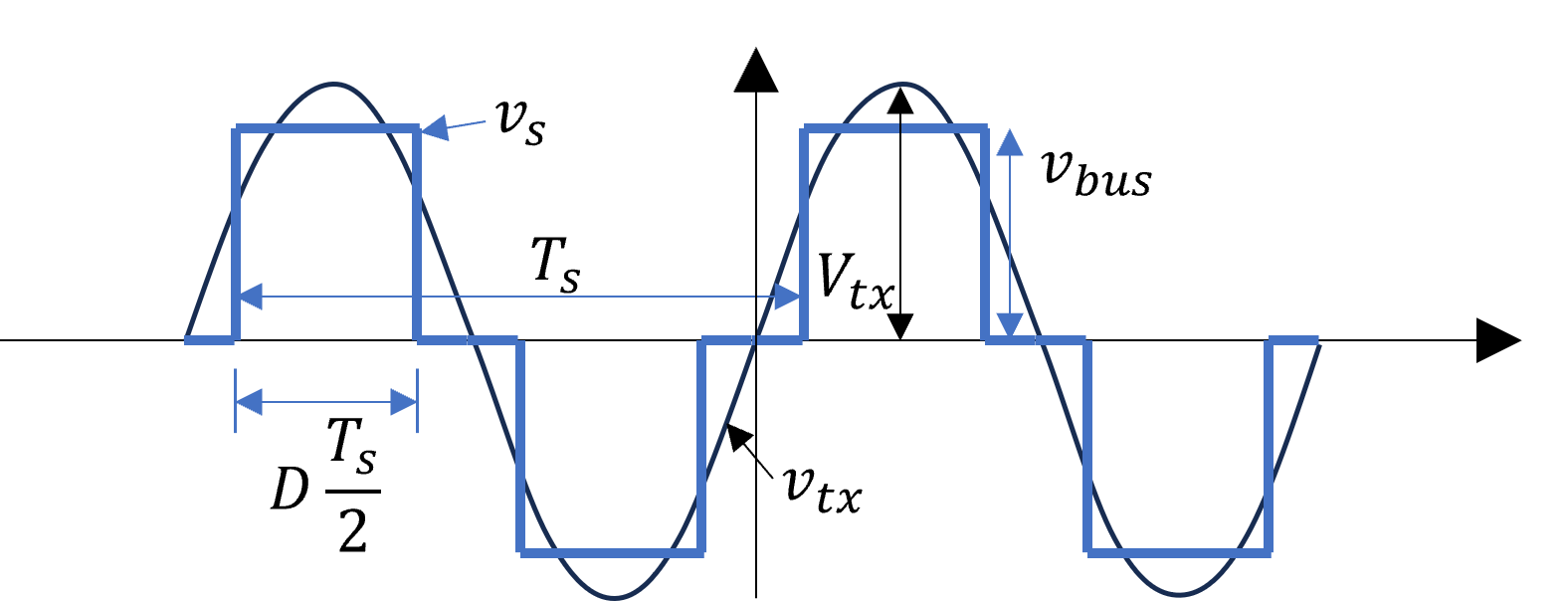
When an inverter operates at a switching frequency with a duty cycle , the waveform of the inverter output voltage is illustrated in Figure 21. is mathematically described by Equation 9 over the interval , where , the period of the switching pattern, is defined as .
| (9) |
If the voltage corresponds to the fundamental harmonic of at frequency and the amplitude of the fundamental of at is , when filtered through a resonance tank that only retains the fundamental component, the voltage can be expressed as:
| (10) |