StableLego: Stability Analysis of Block Stacking Assembly
Abstract
Recent advancements in robotics enable robots to accomplish complex assembly tasks. However, designing an assembly requires a non-trivial effort since a slight variation in the design could significantly affect the task feasibility. It is critical to ensure the physical feasibility of the assembly design so that the assembly task can be successfully executed. To address the challenge, this paper studies the physical stability of assembly structures, in particular, block stacking assembly, where people use cubic blocks to build 3D structures (e.g., Lego constructions). The paper proposes a new optimization formulation, which optimizes over force balancing equations, for inferring the structural stability of 3D block-stacking structures. The proposed stability analysis is tested and verified on hand-crafted Lego examples. The experiment results demonstrate that the proposed stability analysis can correctly predict whether the structure is stable. In addition, it outperforms the existing methods since it can locate the weakest parts in the design, and more importantly, solve any given assembly structure. To further validate the proposed analysis formulation, we provide StableLego: a comprehensive dataset including more than 50k 3D objects with their Lego layouts. We test the proposed stability analysis and include the stability inference for each corresponding object in StableLego. Our code and the dataset are available at https://github.com/intelligent-control-lab/StableLego.
I Introduction
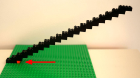
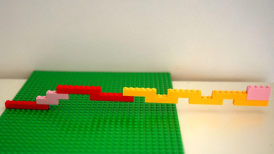
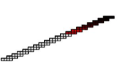
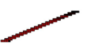
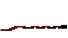
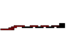
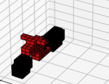
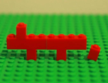
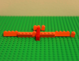
Recent advancements in robotics enable intelligent robots to perform assembly tasks, such as Lego construction [1, 2, 3], toy insertion [4], electronic assembly [5], automotive assembly [6, 7], etc. Before the robots perform the actual assembly, a feasible assembly design is necessary. However, a good assembly requires a non-trivial effort to design since a slight variation could significantly affect the task feasibility. Figure 1 showcases examples of both valid and invalid Lego assembly designs. Two valid Lego designs are shown in Fig. 1(1) and 1(4). However, tiny modifications, e.g., adding one more brick as depicted in Fig. 1(2) and 1(5), can cause the designs to collapse. Interestingly, the same small adjustment can stabilize collapsing assemblies, as seen in Fig. 1(3) and 1(6). Despite the significant impact, these slight variations are barely perceivable to humans. Conventional approaches leverage rapid prototyping techniques, e.g., Computer-aided Design (CAD), to iteratively improve the structure design [8]. However, assembly prototyping is usually time-consuming since it requires multiple components to fit well, making the iterative process expensive.


Structural stability is a key factor that influences the feasibility of an assembly design. In particular, this paper focuses on block stacking assembly, where people use different blocks to build 3D structures. Specifically, we focus on Lego assembly, but the proposed method can be generalized to other block stacking assemblies. Lego consists of a wide variety of standardized cubic Lego bricks with different dimensions and colors, which allows users to freely create customized structures. The top left diagram of Fig. 2 illustrates the interlocking mechanism of Lego assembly. A Lego brick is stacked on top of another to form an assembly by inserting the knob into the cavity. The tight fit of the insertion causes deformation, which generates friction to hold the assembly stable. It is important to ensure that the assembly design is stable (i.e., will not collapse) so that an agent can safely perform the construction. Recent works leverage computer-aided techniques (e.g., simulations) to predict the structural stability of the design [9, 10]. However, to the best of our knowledge, existing simulations are not able to easily simulate the deformation and the resulting friction between Lego bricks. Therefore, it is challenging to evaluate the stability of a given structure.

To address the challenge, this paper proposes a new optimization formulation to infer the stability of block-stacking structures. This formulation leverages the rigid block equilibrium (RBE) method and optimizes over force-balancing equations. The proposed method is tested and verified on hand-crafted Lego examples. The experiment results demonstrate that the proposed stability analysis can correctly predict whether the structure is stable. In addition, it outperforms the existing methods since it can locate the weakest parts in the design and, more importantly, solve any given assembly structure. To further validate our method, we provide StableLego: a comprehensive Lego assembly dataset, which includes a wide variety of Lego assembly designs for real-world objects. StableLego is a novel benchmark that could facilitate research in related areas. The dataset includes more than 50k Lego structures built using standardized Lego bricks with different dimensions. We apply the proposed stability analysis to the dataset and include the stability inferences in the dataset. To the best of our knowledge, StableLego is the first Lego assembly dataset with stability inferences. Our stability analysis implementation and the StableLego dataset are available at https://github.com/intelligent-control-lab/StableLego.
II Related Works
In this paper, we mainly focus on the structural stability of block stacking structures [11, 12]. The finite element method (FEM) is widely used in analyzing complex assembly structures [13]. However, it is usually time-consuming if accuracy is required [14]. For specific assembly structures, e.g., Lego assembly, existing works design rules to intuitively evaluate the structural stability and improve the assembly design [15, 16, 17, 18, 19, 20, 21]. Such rules can be, for instance, maximizing the number of brick knob-to-cavity connections; minimizing the number of bricks; and maximizing the number of brick orientation alternations. Although these rules provide insights into Lego structural stability, they are difficult to apply to other block assembly tasks. Moreover, these pre-defined rules only provide intuitive understanding instead of quantitative measurements with physical implications. Recent works [9, 10] leverage simulators with a physics engine to simulate the behavior of assembly structures. However, it is difficult to simulate the interlocking mechanism between Lego bricks with existing simulators. Therefore, only block stacking with smooth surfaces can be addressed. Furthermore, Kim et al. [9] only assess whether the structure would fall as a whole without considering potential collapse triggered by internal stresses. Another recent work [22] directly trains a neural network to predict stability. However, such learning-based approaches require a significant amount of data, which is non-trivial to generate. In contrast, our method does not require training and provides a quantitative stability assessment that can be applied to generic block stacking structures.
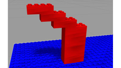
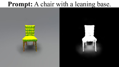
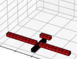
On the other hand, rigid block equilibrium (RBE) is also widely used to evaluate the structural stability of block stacking assembly [23, 24]. This approach formulates stability analysis as an optimization problem, solving for a force distribution that satisfies the static equilibrium constraints. Recent works [25, 26, 27] have utilized RBE-based techniques to optimize Lego layouts. However, these existing methods assume that the block assembly design is single-connected, i.e., every brick in the assembly is connected to the ground. Figures 3 and 3 illustrate examples of Lego designs that are respectively single-connected and not single-connected. The design in Fig. 3 is not single-connected as the top three bricks do not have a connected path to the ground. Those existing methods fail to solve such designs that are not single-connected. Although standardized assembly designs usually assert single-connectivity, preliminary raw designs, e.g., a design from generative AI, may violate this assumption, e.g., it might contain floating bricks. Figure 3 illustrates an example 3D structure from generative AI [28] with its corresponding prompt. Even though the overall 3D structure is reasonable, the corresponding Lego design could be imperfect as shown in Fig. 3 since it contains floating bricks (i.e., the white bricks in Fig. 3). Such a design violates the single-connected assumption and is not solvable by existing methods. Contrarily, our method can effectively address these cases.

III Stability Analysis of Block Stacking Structures
This section focuses on stability analysis for block stacking assembly. We formulate the stability analysis as an optimization problem following the idea in RBE [23], which optimizes over force balancing equations. Lego assembly, a special category of block stacking assembly, presents additional complexities due to the interlocking mechanism between bricks. Therefore, we will introduce our analysis formulation based on Lego. In particular, we assume all connections between bricks are well-established, i.e., all cavities and knobs are snapped together for all connections. The proposed formulation can be easily reduced to regular block stacking assembly by removing the interlocking constraints.
III-A Force Model
Figure 2 illustrates the force model in our stability analysis, which is adopted from Luo et al. [25]. The middle diagram of Fig. 2 depicts the potential forces exerted on a single Lego brick in an assembly. Given an assembly consisting of bricks, we denote a brick as , where . For any , it has the gravity applying on it, where is the brick mass and . If there is a connection to the top knob, will experience pressing force (i.e., the blue arrow) pointing downward due to the weight of the structures above it, as well as pulling force (i.e., the red arrow) pointing upward due to the tight connection of the knob. Similarly, if there is a connection to the bottom cavity, will experience supporting force (i.e., the purple arrow) pointing upward due to the rigid structure below it, as well as dragging force (i.e., the green arrow) pointing downward due to the friction from the connection. If there are bricks right next to , there will also be horizontal press (i.e., the yellow arrows) pointing toward . If a knob or a cavity of is connected, there will be horizontal press within the knob (i.e., the cyan arrows) pointing in horizontal directions that prevent the brick from sliding. Note that each connection will generate 4 horizontal press force components in the 4 horizontal directions, i.e., and , pointing inward to . Also, note that only is a force constantly exerting on independent of the assembly structure. are forces that may or may not exist depending on the structure. In the following discussion, we refer to these forces as candidate forces.
The middle and bottom figures on the left of Fig. 2 illustrate different connections of bricks. Depending on the different dimensions of the top bricks, there are different numbers of contacting points that generate friction to hold the knobs of the bottom bricks. If the top brick is , where , each connected knob has 4 contact points. If the top brick is , , each connected knob has 3 contact points. If the top brick is , , the connections on the edge have 3 contact points while others have 4 contact points. In our formulation, instead of summing up the candidate forces and assuming only one vertical candidate for each of the within each knob-to-cavity connection, we assume the vertical candidate forces exist at each of the contact points.
The right figure in Fig. 2 illustrates the force models for each brick in an example Lego structure. The white contours indicate the connected knobs for each brick. If there is no connection, either on top or below a knob, there are no candidate forces exist. The bottom of the diagram lists all the potential forces that are exerted on the brick. All bricks have gravity applied to them. For , since only the right-most knob has a brick connected on top of it, it has 4 pressing candidates and 4 pulling candidates since the connection has 4 contact points. And there exist 4 knob pressing candidates in 4 horizontal directions. Since there exists a brick (i.e., ) right next to it, it has a horizontal press candidate . Similarly for , since there are only connections below it, there is no or . Due to the cavity connections, there are 8 supporting candidates since each cavity has 4 contact points. Similarly there are 8 dragging candidates and 8 knob pressing candidates . Since there is no brick right next to , does not exist. We can derive the force models for and following the similar rules as listed in Fig. 2.
III-B Static Equilibrium
An object reaching static equilibrium indicates that it will not fall or collapse. To ensure a stable Lego structure, we need to ensure that each brick can reach static equilibrium so that the structure will not collapse. For a given Lego structure with bricks and each candidate force has candidates, the static equilibrium enforces that , we need to satisfy
| (1) | ||||
| (2) | ||||
where denotes the vector cross-product operation. is the force lever of the force vector on brick . Equation 1 enforces that reaches force equilibrium so that the brick would not have translational motion. Equation 2 enforces that reaches torque equilibrium. This indicates that the brick would not have rotational motion. Satisfying both 1 and 2 indicates that the bricks are static and the structure is stable.
III-C Constraints
Non-negativity
We assume all components are rigid bodies. Therefore, the value of each force should be non-negative. Let the value of be , we have
| (3) |
Non-coexistence
At any given contact point, the pulling force and the pressing force cannot coexist. If , the top brick is pulling the bottom brick upward. Then there is no weight loaded on the bottom brick, and thus, . If , then there is weight loaded on the bottom brick. Therefore, the top brick cannot be pulling the bottom brick upward. Similarly, the dragging force and the supporting force cannot coexist. The non-coexistence property gives the constraint as
| (4) |
Equality
Newton’s third law states that for every action, there is an equal and opposite reaction. At a given contact point , let the bottom brick be and the upper brick be . The supporting force and the pressing force are such an action-reaction pair. Similarly, the pulling force and the dragging force are also an action-reaction pair. Also, the knob pressing candidates and are also action-reaction pairs. Let be a brick adjacent to , then the horizontal press and are also an action-reaction pairs. Therefore, we have the equality constraints as
| (5) |

Friction Capacity
As shown in the left diagram of Fig. 2, Lego bricks are held together due to the static friction (i.e., and ) at the contact points caused by deformation. The structure is stable if the friction is within the limit. In our analysis, we assume all deformations are identical and all frictions share the same limit . A structure is stable if all friction forces do not exceed the limit. Thus, we have the capacity constraint as
| (6) |
III-D Stability Analysis Formulation
Following the intuition in RBE [25], a given structure is stable if there exists a set of forces that satisfies 1, 2, 3, 4, 5 and 6. We can use the force distribution to estimate the stability of the structure. To solve , we formulate the optimization as
| (7) |
where is the maximum dragging force for a brick . The objective function minimizes the static equilibrium values in 1 and 2 as well as the maximum friction and the total friction in each brick. The terms and encourage the solver to solve a distribution of that makes the structure to reach static equilibrium. tries to avoid extreme values among the dragging forces in . And encourages the solver to solve with minimum internal friction. and are tunable weights to adjust the influence of the two terms so that they do not take over the effect of the static equilibrium. Note that the key difference between 7 and previous works is that instead of imposing static equilibrium 1 and 2 as equality constraints, we encode them in the objective function. This is critical since enforcing them as constraints is essentially assuming there exists a that satisfies the static equilibrium. If a given structure does not have such a , the formulation is voided. An example could be a structure with floating bricks. Including them in the objective function instead of as hard constraints can relax the single-connected assumption and solve the stability of any structures. Aside from the objective function, 7 also imposes more equality constraints (i.e., 4 and 5) than prior works to improve the accuracy of predicted stability.
Given the solved , the stability of each brick is estimated as
| (8) |
The structure is stable if all bricks are stable, i.e., . It is worth noting that the friction capacity 6 is not imposed as a constraint in 7. Instead, we add the friction terms in the objective function to minimize the solved internal friction. And use 6 in 8 to determine the structural stability.
IV Experiments
In our experiments, we consider standard Lego bricks, i.e., rectangular bricks with solid colors and a height being . Table I shows the masses we measured for popular standard Lego bricks. Bricks with dimension are uncommon on the market, and thus, we mainly consider and bricks. To avoid uncertainty in manufacturing, each brick’s mass is measured using the average mass of 10 bricks with identical dimensions. In particular, we use bricks that are highlighted in table I since they are most commonly used 111https://www.lego.com/en-us/product/lots-of-bricks-11030. We manually measured the friction capacity . The stability analysis is implemented using Python and Gurobi [29]. We set and . Our implementation is available at https://github.com/intelligent-control-lab/StableLego. All results are generated on a PC with an Intel i7-13700HX CPU and 32GB RAM.
| Dimension | ||||
|---|---|---|---|---|
| Mass (g) | 0.43 | 0.81 | 1.57 | 2.28 |
| Dimension | ||||
| Mass (g) | 3.03 | 1.15 | 2.16 | 3.23 |
IV-A Stability Analysis Accuracy
We implemented Luo et al. [25] as our baseline and evaluated our stability analysis algorithm on multiple hand-crafted Lego structures. Figure 4 illustrates the comparisons between our analysis results and the baseline’s prediction. We apply the stability analysis methods to the structures in Fig. 1. The top row shows the stability results by solving 7, and the bottom row displays the results using the baseline. Figures 4 and 4 correspond to the structure in Fig. 1(1). The structure can be built in real, and both methods indicate that the structure is stable. However, the proposed formulation 7 indicates higher internal stress at lower levels, whereas the baseline cannot distinguish the stresses at different levels. The structure in Fig. 1(2) collapses, and both methods indicate that the structure is unstable. However, ours accurately predicts the collapsing point (i.e., the white brick in Fig. 4) while the baseline cannot as shown in Fig. 4. To observe the actual collapsing point, we build these structures in real. Specifically, we hold the structure before it is finished so it does not collapse during construction. After all connections are established, we remove the external support and observe the collapsing point. As shown in Fig. 1(2), the structure indeed collapses at the predicted location. Similar results are shown in Fig. 4, 4, 4, 4, 4, 4, 4 and 4, which correspond to the structures in Fig. 1(3), 1(4), 1(5) and 1(6). We can see that even though both methods can estimate structural stability, ours gives a more precise estimation, which predicts the weakest connection points. This is important since it provides insight into improving the brick layout design to construct a stable structure as shown in Fig. 1.


IV-B StableLego Dataset
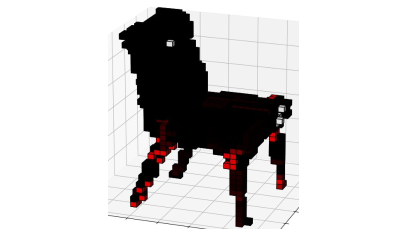
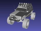
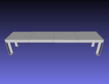
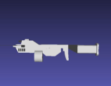
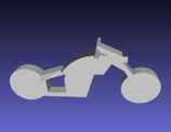
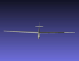
A large-scale dataset is essential for benchmarking various assembly tasks. However, it is time-consuming to design a large number of different Lego objects manually. To this end, we present StableLego, a comprehensive dataset that provides artificially generated Lego brick layouts for a wide variety of different 3D objects. StableLego is developed based on the ShapeNetCore dataset [30]. It includes more than k of different objects from 55 common object categories with their Lego layouts. For each object, we downsample the original 3D object to a grid world and generate a corresponding brick layout layer by layer. In particular, we merge unit voxels (i.e., ) into larger bricks and prioritize merging voxels that have no support under them. Note that the focus of this dataset is not providing optimal brick layouts. Thus, the dataset contains a mix of valid and invalid brick layouts for testing the stability analysis accuracy. The top and third rows in Fig. 5 and 6 illustrate examples of the 3D objects and the corresponding Lego structures. The dataset could be used to inspire creativity in building Lego objects. More importantly, it provides a novel benchmarking platform for verifying the performance of structure stability algorithms as well as facilitating research in related areas. We include the stability estimation using the proposed formulation for each Lego structure. Prior work [31] provides a Lego assembly dataset with over 150 designs generated from video input. To the best of our knowledge, StableLego is the first large-scale Lego assembly dataset with stability inferences.
Figure 5 illustrates the stability analysis results of the proposed formulation on example valid designs. The top row shows the original object, and the middle row depicts the stability analysis of the given Lego brick layout. The third row shows the Lego structure built in real following the given brick layout. We can see that our formulation correctly predicts that all structures are stable.
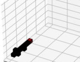
Figure 6 shows examples of invalid Lego designs. We can see that our formulation can correctly estimate the stability by indicating that the structure will collapse. In addition, after removing the external support when finished building, the structures indeed collapse at the predicted collapsing points, as shown in the third row. More importantly, the proposed formulation can estimate the stability regardless of the brick layout. However, the baseline can only solve approximately (i.e., 17k) of the entire dataset. This is because the baseline enforces the static equilibrium as a hard constraint. When the structure violates the single-connected assumption, the baseline cannot estimate the stability of the given structure.
IV-C Stability Analysis Computation Time
Existing methods, e.g., FEM [14], can estimate structural stability, but the computation time is expensive. It is desired that the stability can be efficiently estimated. For the structures in Fig. 1, on average, the analysis results shown in Fig. 4 are solved within overall by our method (i.e., constructing the optimization problem 7 and then solving it), and if we only count the time for solving 7. To quantitatively evaluate the computation efficiency, we test our stability analysis in a controlled setting. In particular, we use unit Lego bricks (i.e., ) to build cuboids with different dimensions up to . The top figure in Fig. 7 shows the computation time for solving the structural stability with different numbers of bricks. We can see that our method is efficient since it can estimate the stability within 1s, and mostly even within 0.5s. The overall computation time (i.e., the dashed lines) is less than 1.5s, and mostly within 1s. As the size of the structure grows, it contains more bricks, and takes longer to estimate the stability. To further evaluate the computation efficiency, we also show the computation time of solving the stability for the Lego structures in StableLego in the bottom figure of Fig. 7. In general, it takes longer time for the structures in StableLego since it contains a wide variety of Lego bricks and the structures are more complex. However, our method is still able to solve efficiently. When having less than 300 bricks, our method can solve within 1s. As the number of bricks grows, the complexity increases, and it takes a longer time. But we can still expect it to estimate the stability within several seconds.
IV-D Discussion
Extension
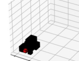
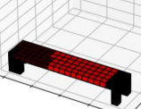
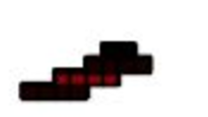
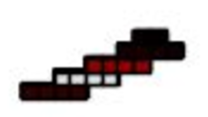
Our experiment only used the highlighted bricks in table I, but the proposed stability analysis formulation applies to other bricks as well. Also, the proposed formulation can be easily extended to regular block stacking assembly, e.g., palletizing, by eliminating the candidate forces caused by the interlocking connections. In addition, it can be extended to account for external forces by specifying large weights for specific bricks where the external forces are applied. Figure 8 illustrates examples of accounting for external loads. A 200 weight is put on the Lego stairs. In the stability analysis, we use a brick with 200 to approximate the weight. Our method indicates that a 3-level stair can support the weight (Fig. 8) while a 4-level stair cannot (Fig. 8). Indeed, Fig. 8 and 8 demonstrate the corresponding stable and unstable structures in real. And the unstable structure indeed breaks at the predicted weakest point.
Future Work
Accounting for external forces can be useful when planning dual-arm Lego assembly when using the manipulation strategy in [1]. The external force could be the assembling arm, and the stability analysis can indicate whether and where a supporting arm is needed. In addition, we can use our approach to efficiently guide generative AI (as shown in Fig. 3 and 3) and improve the imperfect design. Moreover, the proposed stability analysis can be integrated into sequence planning algorithms to generate a feasible assembly plan so that all the intermediate steps are physically valid.


V Conclusion
This paper studies the structural stability of block stacking structures. In particular, this paper leverages the RBE method and proposes a new optimization formulation, which optimizes over force balancing equations, for inferring the structural stability of 3D structures. To benchmark the stability analysis performance, we provide StableLego: a dataset with 3D objects with their Lego layouts and the corresponding stability inferences. The dataset includes a wide variety of assembly configurations (i.e., more than 50k structures) using standardized Lego bricks with different dimensions. The proposed formulation is verified on hand-crafted Lego designs as well as the StableLego dataset.
References
- [1] Liu, R., Sun, Y., and Liu, C., 2023. “A lightweight and transferable design for robust lego manipulation”. arXiv preprint arXiv:2309.02354.
- [2] Liu, R., Chen, A., Luo, X., and Liu, C., 2023. “Simulation-aided learning from demonstration for robotic lego construction”. arXiv preprint arXiv:2309.11010.
- [3] Liu, R., Sun, Y., and Liu, C., 2023. “Robotic lego assembly and disassembly from human demonstration”. arXiv preprint arXiv:2305.15667.
- [4] Liu, R., Chen, R., Abuduweili, A., and Liu, C., 2023. “Proactive human-robot co-assembly: Leveraging human intention prediction and robust safe control”. In 2023 IEEE Conference on Control Technology and Applications (CCTA), pp. 339–345.
- [5] Tian, W., Ding, Y., Du, X., Li, K., Wang, Z., Wang, C., Deng, C., and Liao, W., 2023. “A review of intelligent assembly technology of small electronic equipment”. Micromachines, 14(6).
- [6] Michalos, G., Makris, S., Papakostas, N., Mourtzis, D., and Chryssolouris, G., 2010. “Automotive assembly technologies review: challenges and outlook for a flexible and adaptive approach”. CIRP Journal of Manufacturing Science and Technology, 2(2), pp. 81–91.
- [7] Trommnau, J., Kühnle, J., Siegert, J., Inderka, R., and Bauernhansl, T., 2019. “Overview of the state of the art in the production process of automotive wire harnesses, current research and future trends”. Procedia CIRP, 81, pp. 387–392.
- [8] Pham, D., and Gault, R., 1998. “A comparison of rapid prototyping technologies”. International Journal of Machine Tools and Manufacture, 38(10), pp. 1257–1287.
- [9] Kim, J., Chung, H., Lee, J., Cho, M., and Park, J., 2020. “Combinatorial 3d shape generation via sequential assembly”. arXiv preprint arXiv:2004.07414.
- [10] Cannizzaro, R., Routley, J., and Kunze, L., 2023. “Towards a causal probabilistic framework for prediction, action-selection & explanations for robot block-stacking tasks”. arXiv preprint arXiv:2308.06203.
- [11] Kim, J. W., 2014. “Survey on automated lego assembly construction”.
- [12] Wang, Z., Song, P., and Pauly, M., 2021. “State of the art on computational design of assemblies with rigid parts”. Computer Graphics Forum, 40(2), pp. 633–657.
- [13] Zhou, C., Tang, B., Ding, L., Sekula, P., Zhou, Y., and Zhang, Z., 2020. “Design and automated assembly of planetary lego brick for lunar in-situ construction”. Automation in Construction, 118, p. 103282.
- [14] Pletz, M., and Drvoderic, M. “Brickfem an automated finite element model for static and dynamic simulations of simple lego® sets”.
- [15] Gower, R., Heydtmann, A., and Petersen, H., 1998. “Lego: Automated model construction”.
- [16] Smal, E., 2008. “Automated brick sculpture construction”. PhD thesis, Stellenbosch: Stellenbosch University.
- [17] Ono, S., Andre, A., Chang, Y., and Nakajima, M., 2013. “Lego builder: Automatic generation of lego assembly manual from 3d polygon model”. ITE Transactions on Media Technology and Applications, 1, 10, pp. 354–360.
- [18] Testuz, R. P., Schwartzburg, Y., and Pauly, M., 2013. Automatic generation of constructable brick sculptures. Tech. rep.
- [19] Lee, S.-M., Kim, J. W., and Myung, H., 2018. “Split-and-merge-based genetic algorithm (sm-ga) for lego brick sculpture optimization”. IEEE Access, 6, pp. 40429–40438.
- [20] Petrovic, P., 2001. “Solving lego brick layout problem using evolutionary algorithms”. In Proceedings to Norwegian Conference on Computer Science, Citeseer.
- [21] Zhou, J., Chen, X., and Xu, Y., 2019. “Automatic Generation of Vivid LEGO Architectural Sculptures”. Computer Graphics Forum.
- [22] Groth, O., Fuchs, F. B., Posner, I., and Vedaldi, A., 2018. “Shapestacks: Learning vision-based physical intuition for generalised object stacking”. In Proceedings of the european conference on computer vision (eccv), pp. 702–717.
- [23] Whiting, E., Ochsendorf, J., and Durand, F., 2009. “Procedural modeling of structurally-sound masonry buildings”. ACM Trans. Graph., 28(5), dec, p. 1–9.
- [24] Kao, G. T.-C., Iannuzzo, A., Thomaszewski, B., Coros, S., Van Mele, T., and Block, P., 2022. “Coupled rigid-block analysis: Stability-aware design of complex discrete-element assemblies”. Computer-Aided Design, 146, p. 103216.
- [25] Luo, S.-J., Yue, Y., Huang, C.-K., Chung, Y.-H., Imai, S., Nishita, T., and Chen, B.-Y., 2015. “Legolization: Optimizing lego designs”. ACM Trans. Graph., 34(6), nov.
- [26] Kollsker, T., and Malaguti, E., 2021. “Models and algorithms for optimising two-dimensional lego constructions”. European Journal of Operational Research, 289(1), pp. 270–284.
- [27] Kollsker, T., and Stidsen, T. J., 2021. “Optimisation and static equilibrium of three-dimensional lego constructions”. In Operations Research Forum, Vol. 2, Springer, pp. 1–52.
- [28] Poole, B., Jain, A., Barron, J. T., and Mildenhall, B., 2022. “Dreamfusion: Text-to-3d using 2d diffusion”. arXiv.
- [29] Gurobi Optimization, LLC, 2023. Gurobi Optimizer Reference Manual.
- [30] Chang, A. X., Funkhouser, T., Guibas, L., Hanrahan, P., Huang, Q., Li, Z., Savarese, S., Savva, M., Song, S., Su, H., Xiao, J., Yi, L., and Yu, F., 2015. ShapeNet: An Information-Rich 3D Model Repository. Tech. Rep. arXiv:1512.03012 [cs.GR], Stanford University — Princeton University — Toyota Technological Institute at Chicago.
- [31] Li, K., Bian, J.-W., Castle, R., Torr, P. H., and Prisacariu, V. A., 2023. “Mobilebrick: Building lego for 3d reconstruction on mobile devices”. In Proceedings of the IEEE/CVF Conference on Computer Vision and Pattern Recognition (CVPR), pp. 4892–4901.