Long-Range Backscatter Connectivity via Spaceborne Synthetic Aperture Radar
Abstract.
SARComm is a new communication method that enables passive satellite backscatter connectivity using existing spaceborne synthetic aperture radar (SAR) signals. We demonstrate that SAR signals from the European Space Agency’s Sentinel-1 satellite, used for imaging the Earth, can also be leveraged to enable ground-to-satellite connectivity. This paper presents the first cooperative, on-the-ground target that modulates SAR backscatter to send information bits and analyzes how to extract it from publicly available Sentinel-1 datasets. To demonstrate the system’s feasibility, we evaluate the effectiveness of corner reflectors in the field, develop a deployment algorithm to optimize reflector placement and prototype modulating corner reflectors (both mechanically and electrically controlled) to change the amplitude of backscattered SAR signals.
1. Introduction
Despite the technological advancements in today’s wireless connectivity solutions, enabling Internet connectivity everywhere on Earth remains an unsolved problem. A vast portion of the planet remains out of reach for smart systems due to the lack of communication infrastructure. In addition, nearly 37% of the population lacks Internet connectivity due to limited resources and government censorship (Nations, 2021). Most of the biomes critical to monitoring climate change (i.e., oceans and rainforests) are located in remote areas that would benefit from closer monitoring but are inaccessible to existing sensing technologies. The creation of a universally accessible connectivity solution would significantly expand humanity’s understanding of the environment and enable a more connected world.
Launching new satellite constellations has taken a step towards solving this problem, where Internet connectivity can be enabled without requiring large-scale terrestrial infrastructure (Starlink, 2023). In fact, there are over 5,500 active satellites orbiting Earth, and this number is expected to increase to 58,000 by 2030 (Office, 2022). Beyond providing broadband connectivity, these satellites are also used to perform tasks such as monitoring Earth’s ecosystem using remote sensing techniques (Agency, 2023c). Most recently, satellites are being launched, typically in low-earth-orbit (LEO), to enable long-range wireless communication for Internet of Things (IoT) applications (SWARM, 2023; Network, 2023). These solutions have the potential to expand the sensing capabilities of IoT systems to more remote environments such as forests, oceans, and tundras to improve our understanding of climate change impacts.
While promising, even satellite connectivity has its shortcomings. Deploying long-lived sensing systems or enabling Internet connectivity in remote and resource-constrained environments remains a challenge with today’s solutions. Large-scale environmental monitoring systems need to function without power infrastructure and on very limited budgets. Therefore, solutions must be low-power, cost-effective, and require minimal maintenance. Existing satellite connectivity solutions are prohibitively expensive both in terms of launching new satellites to expand their reach and the cost of the service itself (SWARM, 2023). Moreover, launching new satellites exacerbates issues related to spectrum efficiency, co-existence between space and terrestrial communication networks, and space debris (Observatory, 2023; Agency, 2023a). To this end, we pose the following question: is there a way to repurpose existing satellite infrastructure to enable new methods of ground-to-satellite communication?
This paper presents satellite backscatter-enabled communication (SARComm), a novel method of enabling passive low-power satellite backscatter connectivity by leveraging existing satellite infrastructure. Our key insight is that instead of relying on active radios and new satellite constellations in an already crowded spectrum, we can exploit signals from existing satellites to enable low-power passive ground-to-satellite connectivity. However, enabling this is non-trivial and requires addressing two key issues: (1) enabling passive wireless connectivity at distances as far as 2,000 kilometers and (2) retrieving and processing the data without requiring custom hardware or introducing new terrestrial infrastructure (e.g., ground stations).
Our approach leverages satellites equipped with radar systems used for remote sensing applications. Sentinel-1, for example, uses synthetic aperture radar (SAR), where a pulsed signal is transmitted, and the backscattered signal is observed to gain insights into Earth’s terrain and create images of the Earth. Sentinel-1 is designed to receive backscatter signals, and this presents an opportunity to reuse these ambient satellite signals to enable long-range and low-power backscatter communication. Similar to RFID, a satellite imaging system could act as the reader for low-power devices on the ground that modulate existing satellite signals. By changing the reflectivity of an object on the ground, we can modulate the spaceborne SAR signals and wirelessly transmit information bits with near zero power. However, compared to existing ambient backscatter techniques, this is quite challenging. First, Sentinel-1 has an imaging resolution of 22x3 m (Agency, 2024a), meaning that the target on the ground needs to have a very large radar cross-section (RCS) in order to detect any change and have a stronger backscattered signal compared to the surrounding environment. Second, in most areas, Sentinel-1 collects data every 12 days, and for any particular area of interest, the data collection period is only 2.75 seconds (Online, 2024). Lastly, while Sentinel-1 data is publicly accessible, existing data processing techniques are designed for imaging and not communication, thus requiring the development of complex data processing pipelines.
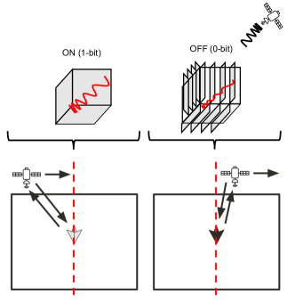
SARComm solves these challenges by leveraging corner reflectors to optimize radar cross section and designing them in such a way that they can switch between reflective and non-reflective states (see Figure 1). This allows SARComm to wirelessly transmit information by modulating an incoming SAR signal. To ensure that data can be reliably transmitted, we optimize the RCS of the corner reflector by identifying locations with minimal background clutter for any given region and determining the optimal angle and orientation during the satellite pass. Instead of relying on existing Sentinel-1 SAR data processing techniques that only produces a single resolved image every pass, SARComm uses a new data processing pipeline that allows for multiple bits of data to be transmitted by producing multiple images each time the satellite passes.
We make the following key contributions:
-
(1)
We present a new method to enable passive satellite backscatter connectivity using the European Space Agency’s Sentinel-1 Mission.
-
(2)
We demonstrate that by developing modulated corner reflectors, we can manipulate the reflectivity of objects on the ground, and observe these changes at distances as far as 2,000 km.
-
(3)
We construct a placement algorithm that identifies optimal corner reflector deployment sites within a region of interest and provides the ideal reflector tilt angle and bearing.
-
(4)
We introduce a new SAR processing pipeline for wireless communication, which generates independent images from subsets of SAR data to transmit multiple bits in a single satellite pass.

2. Background
This section describes the two main existing technologies we use–Sentinel-1 mission with synthetic aperture radar (SAR) and corner reflectors.
The Sentinel-1 mission captures RF reflections from earth using active transmissions during its flight. The reflections received as the satellite is in motion are stitched together to form a much larger synthetic antenna array than the physical antenna array on the satellite.
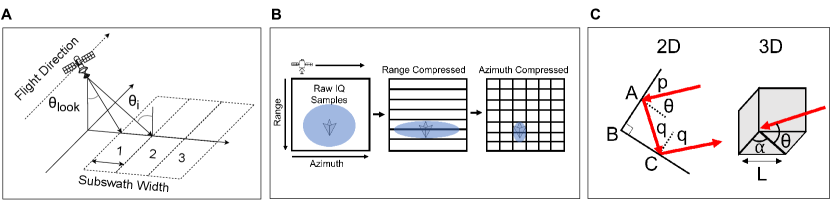
Corner reflectors reflect signals back at a transmitter at a range of incident angles. Figure 3C shows how this is achieved in a simple 2D corner reflector. We extend the corner reflector to send bits of data by dynamically modifying its reflectivity both mechanically and electronically.
The combination of modified SAR signal processing and modulated corner reflector enables us to send multiple bits of data back to the satellite using a physically small structure visible to the satellite.
2.1. Sentinel-1 Mission
The ESA’s Sentinel-1 mission is a satellite constellation that provides open-source C-Band SAR data. It is deployed in LEO at 700 km above the Earth’s surface. Sentinel-1 operates at 5.4 GHz, and due to this relatively long wavelength, these SAR systems can image the Earth day and night regardless of weather conditions. The Sentinel-1A satellite is currently in orbit and images Earth in 12-day cycles, with some locations revisited more frequently than others.
SAR Signal Processing. SAR processing is typically done in two steps: range and azimuth compression. At a high level, the raw burst data is sorted into range and azimuth bins to form the pixels of the resolved image, as shown in Figure 3B. SAR systems transmit linearly frequency-modulated signals called chirps. They receive the backscattered chirps (also referred to as echoes) after they reflect off of Earth’s surface. Given the time that it takes these echoes to return and the known shape of the chirp, the range of the return echoes can be derived. The chirps are transmitted at a defined pulse repetition frequency (PRF), which is frequent enough such that any area of interest is characterized by multiple receive echoes as the satellite passes overhead. SAR systems use have enhanced azimuth resolution compared to traditional radar, which is achieved by using the Doppler shift caused by the known movement of the satellite to determine a target’s location in the azimuth direction.
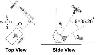
Acquisition Modes. Sentinel-1 has four different acquisition modes: Stripmap, Interferometric Wide Swath (IW), Extra-Wide Swath, and Wave. IW is the primary mode used, covering most of the land on earth. In IW mode the radar uses beam steering to cover more area and generate an image with more consistent resolution. The beam is steered to capture separate bursts in the azimuth direction and between three different range sections called subswaths. The look angle () and incidence angle (), which are equivalent if the ground is flat (see Figure 3A). The drawback of IW mode is that less time is spent imaging the same location, reducing the final image’s azimuth resolution. IW modes achieve a range resolution of about 3 m and azimuth resolution of 22 m. In this mode, two polarizations are measured, co-polarization (VV) and cross-polarization (VH), meaning that it transmits in the vertical polarization and receives vertically and horizontally. This results in two polarization images generated from each dataset.
Data Format and Accessibility. The data collected by Sentinel-1 is provided in three different levels: 0, 1, and 2. Level 0 is the measured echo of the radar represented as encoded raw IQ samples. Level 1 data is a resolved image where the raw samples have been compressed in the range and azimuth directions. Finally, Level 2 data products are specially processed for applications such as measuring surface wind speed or ocean surface swell spectrum (Agency, 2023b). This work uses Level 0 data for processing, in addition to two kinds of Level 1 data: Single Look Complex data (SLC) and Ground Range Detected (GRD) data. SLC data is comprised of complex pixels with amplitude and phase information. GRD data only contains amplitude data and has been converted from slant range, distance from the satellite to the object, to ground range, distance from the satellite’s location projected onto the earth to the object. Essentially correcting the satellite’s coordinate systems to spots on the ground.
Sentinel-1 data is readily available, and results for this work were downloaded from the Alaskan Satellite Facility (ASF) using ASF Vertex as well as Microsoft’s Planetary Computer Sentinel-1 data repository (of Alaska Fairbanks, 2024; Source et al., 2022). The data was analyzed using the ESA-provided Sentinel Application Platform (SNAP) and Python using the asf_search package and the planetary_computer package (Agency, 2024c). Each of these platform works with level 1 data and above. The processing of Level 0 data, particularly for IW mode, is complex, and not open source. Therefore, most data analysis begins at Level 1. Several open-source projects have been published to process Level 0 data (Friedt, 2021). However, there is no publicly available processing pipeline for IW data.
2.2. Corner Reflector Theory
Corner reflectors are retroreflectors that passively redirect RF waves back to their emission source. A trihedral corner reflector consists of three orthogonal planes that meet at a common point. Radar Cross Section (RCS) defines how well a reflector reflects signals back at source. The square trihedral corner reflector consisting of three square planes has the largest maximum RCS () among typical reflector designs. Its RCS is given by the expression below (of the Naval Warfare Center Weapons Division, 2013):
| (1) |
where L is the side length of the square panel of the reflector as shown in Figure 3C, and is the wavelength of the incident RF wave (Yang et al., 2023). The maximum RCS is achieved when the incidence angle is parallel to boresight, meaning that is 45° and is 35.26° (Czikhardt et al., 2021) from Figure 3C. The reflector’s RCS defines how much signal will be reflected back and is used in the radar equation to calculate the expected receive power () from a target (of the Naval Warfare Center Weapons Division, 2013):
| (2) |
where is the transmit power, G is the antenna’s gain, and r is the distance from the target. From these equations, it can be seen that the received power of a radar is proportional to the fourth power the side length of a corner reflector. Therefore, the size of the reflector has a large impact on the amount of measured backscatter. In addition to SNR, Signal to Clutter Ratio (SCR) is often used in SAR applications to describe the ratio of a target’s power to the backscattered power from the surrounding environment.
3. System Overview
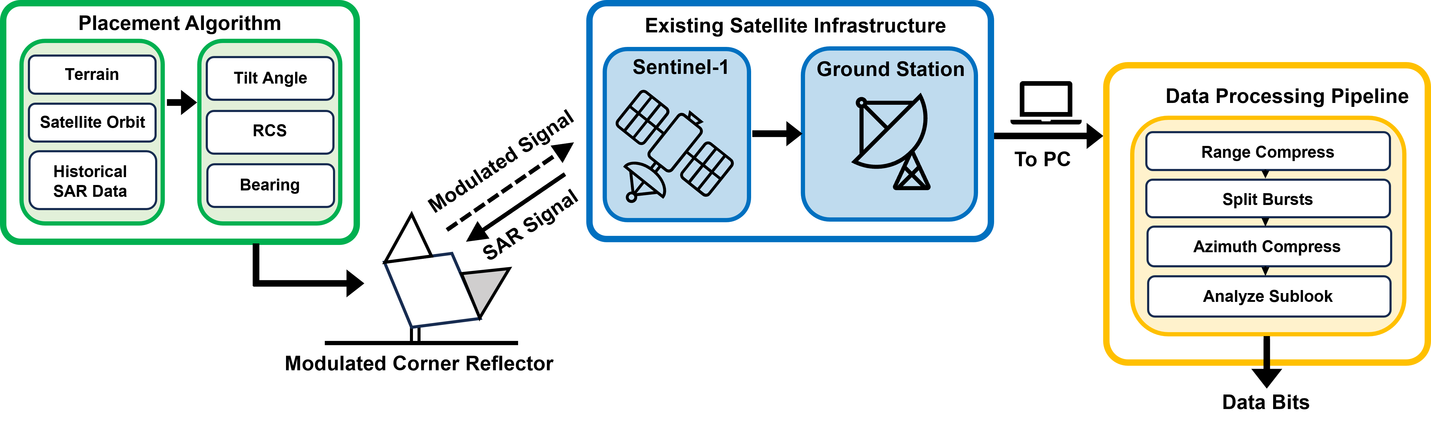
SARComm is a new communication system that enables satellite backscatter connectivity. By utilizing existing satellite infrastructure, such as Sentinel-1, we envision SARComm to be a low-cost and low-power solution to enable connectivity in extremely resource-constrained environments. As shown in Figure 4, SARComm has three key components: a placement algorithm, a modulated corner cube, a receiver (Sentinel-1), and a data processing pipeline.
-
•
Reflector Placement Algorithm. The reflector placement algorithm plays a critical role in optimizing the placement of modulated corner reflector that is used as a transmitter. The algorithm takes into account terrain, satellite orbit information, and historical Sentinel-1 SAR data to specify the optimal location, angles, and size of the corner reflector to maximize its SCR.
-
•
SARComm Modulated Corner Cube. The modulated corner cube switches between reflective and non-reflective states on the order of tens to hundreds of milliseconds while maintaining a large RCS in its reflective state to ensure that data can be sent during the 2.75 seconds (Online, 2024). Since the reflector is designed to switch between two different states, data is transmitted using an ON-OFF keying. The modulated corner reflector can be designed to operate with minimal power consumption by using a low-power microcontroller and RF switch to control the reflector states.
-
•
Sentinel-1 as a Receiver. SARComm does not require deploying new infrastructure. Instead, it relies on existing satellites to receive data. The proposed system uses the Sentinel-1 satellite, which images the Earth and provides publicly available data. We leverage databases such as ASF Data Search (of Alaska Fairbanks, 2024) to access Level-0 (raw I and Q samples) data for any area of interest.
-
•
Data Processing Pipeline. Existing SAR data processing techniques are not designed for wireless communication. We develop a data processing pipeline that splits SAR datasets to produce separate time-independent images from a single satellite pass to extract multiple bits of data. This data processing pipeline has four major steps: range compression, burst splitting, azimuth compression, and image analysis of each sublook image to determine the state of the reflector, which we discuss in detail in Section 4.3.
4. System Design
We evaluate the feasibility of passive ground-to-satellite connectivity using Sentinel-1. First, we deploy corner reflectors to analyze the impact of their RCS on the SCR for various environments and present an algorithm to assist in the deployment of corner reflectors. Second, we design and implement mechanically and electronically modulated corner reflectors and evaluate their performance in controlled settings and field experiments.
4.1. Corner Reflector Placement Algorithm
There are many practical considerations for deployment corner reflectors, including location, the direction and angle of the reflector, and the reflector size relative to the wavelength and desired SCR (Gisinger et al., 2021). To devise a system for optimizing reflector performance based on these factors, we first evaluate the performance of several corner reflector sizes in different environmental scenarios with varying levels of background clutter. We then evaluate the field results to construct a placement algorithm for future reflector deployments.
4.1.1. Deployment Methods
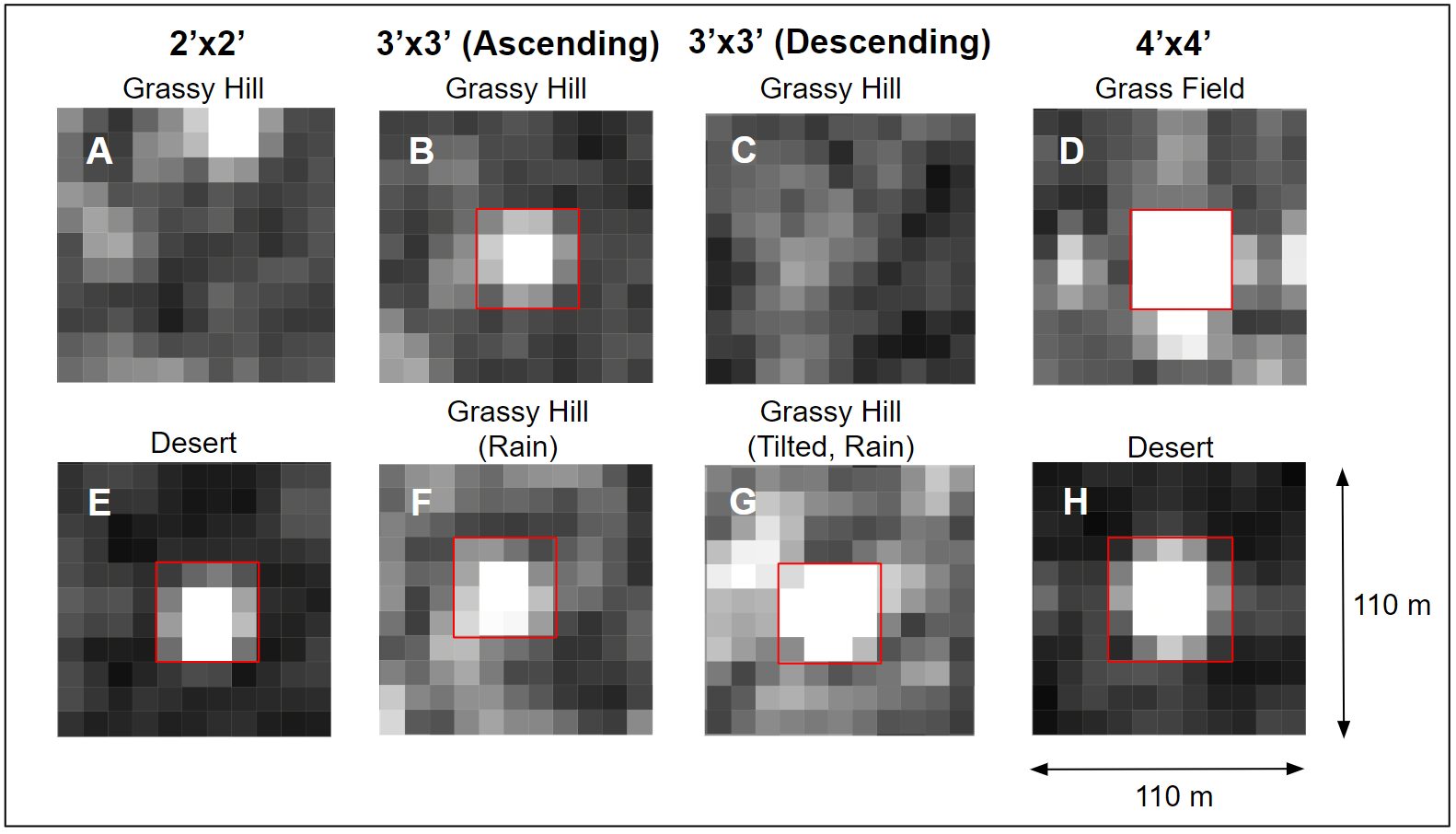
Three different square trihedral corner reflectors with panel sizes of 2x2, 3x3, and 4x4 ft were designed with resulting RCSs of 32.4, 39.3, and 44.4 dB, respectively, at 5.4 GHz. The corner reflectors were deployed at three different geographical locations within the United States: a dry lake bed (desert), a soccer field (grass field), and a natural field surrounded by rolling hills (grassy hill) (see Figure 5). For each deployment, the GPS coordinates of the reflector location were logged, and GRD data was downloaded from ASF (of Alaska Fairbanks, 2024) and analyzed in SNAP (Agency, 2024c).
The reflectors from Figure 5 all feature three square aluminum panels of their respective sizes and a frame that secures the panels in order to ensure their perpendicularity and elevate the panels from the ground. Among the different designs implemented, we found that 80/20 aluminum extrusions (80/20, 2024) provided the best combination of strength-to-weight ratio and ease of assembly for the reflector frames, and our frames are designed so that they can be taken apart and assembled in the field111We release open-source mechanical designs of the constructed corner reflectors at https://anonymous.4open.science/r/SatBEACON-377C/..
4.1.2. Field Results
Figure 5A-H show the 2x2, 3x3, and 4x4 corner reflectors across a range of deployment conditions. In Figure 5A and 5E, the same 2x2 reflector showed up in a clear desert field, but not on the grassy hill. This is likely due to a number of factors, including the difference in background clutter and the unwanted tilt on the hill as opposed to the flat desert floor. Flat areas like water and desert typically have specular reflections that redirect backscatter away from the satellite and thus look less cluttered, as opposed to the more diffuse reflections from rougher surfaces like grassy areas. The effects of weather on SCR can likewise be seen between Figure 5B and 5F, where the surrounding grounds show up significantly brighter after rain, making the corner reflector less distinguishable from the clutter.
All of the reflectors except 5G were placed with the boresight direction of the reflector pointing straight up. Given that the incidence angle of Sentinel-1 in IW mode is 30° to 45° (see Figure 7), pointing the boresight straight up will cause a reduction in the measured RCS. The satellite’s trajectory relative to the reflector’s location will also affect how the reflector is imaged, since Sentinel-1 always scans to its right. As seen between Figure 5B and 5C, the 3x3 reflector placed at the same location does not show up on a clear day during a descending pass even though one could clearly identify it during an ascending pass despite rainy conditions the night before. This can be mitigated by angling the reflector toward the direction of the satellite pass and then tilting its boresight to match the incidence angle of the satellite radar as presented in Figure 7.
The average , or the radar reflectivity per unit area in the ground range, increased from 0.1366 to 0.4417 between Figure 5F and 5G just by improving the reflector’s orientation. Lastly, due to the dependence of RCS on the size of the reflector, larger reflectors tend to have much better RCS (see Figure 5E vs. 5H). The key insight from these results is that the effectiveness of the corner reflector is significantly dependent on both the SCR (environmental factors such as weather and terrain) and RCS (reflector size and orientation relative to satellite pass). With this in mind, we have developed a reflector placement algorithm to optimize performance for various deployment scenarios.
4.1.3. Deployment Algorithm
Many considerations must be made when deploying a modulated corner reflector system. To assist in their successful deployment, the following section describes an algorithm to inform the placement and positioning of reflectors. Our experience deploying corner reflectors in the field showed the importance of considering the weather conditions of the deployment site and properly orienting the reflector. In addition, it is very important to select a site with low background clutter when deploying a modulated reflector to allow the reflector to appear bright when it is ON and dark when it is OFF. Prior work (Czikhardt et al., 2021) introduced a background clutter processor using SnapPy (Culler et al., 2023) to create SCR maps of areas to optimize corner reflector deployment. Our approach deviates from prior work by using SCR as an input to our deployment algorithm rather than an output since typical communication systems all have specific SCR requirements.
The Python algorithm developed in this paper finds the largest area within a provided region that meets this SCR requirement when the reflector is in its ON state and also specifies the ideal bearing () and tilt angles () of the reflector for the chosen deployment location. The algorithm pulls Range Terrain Corrected (RTC) data from Microsoft’s Planetary Computer platform to determine these parameters.
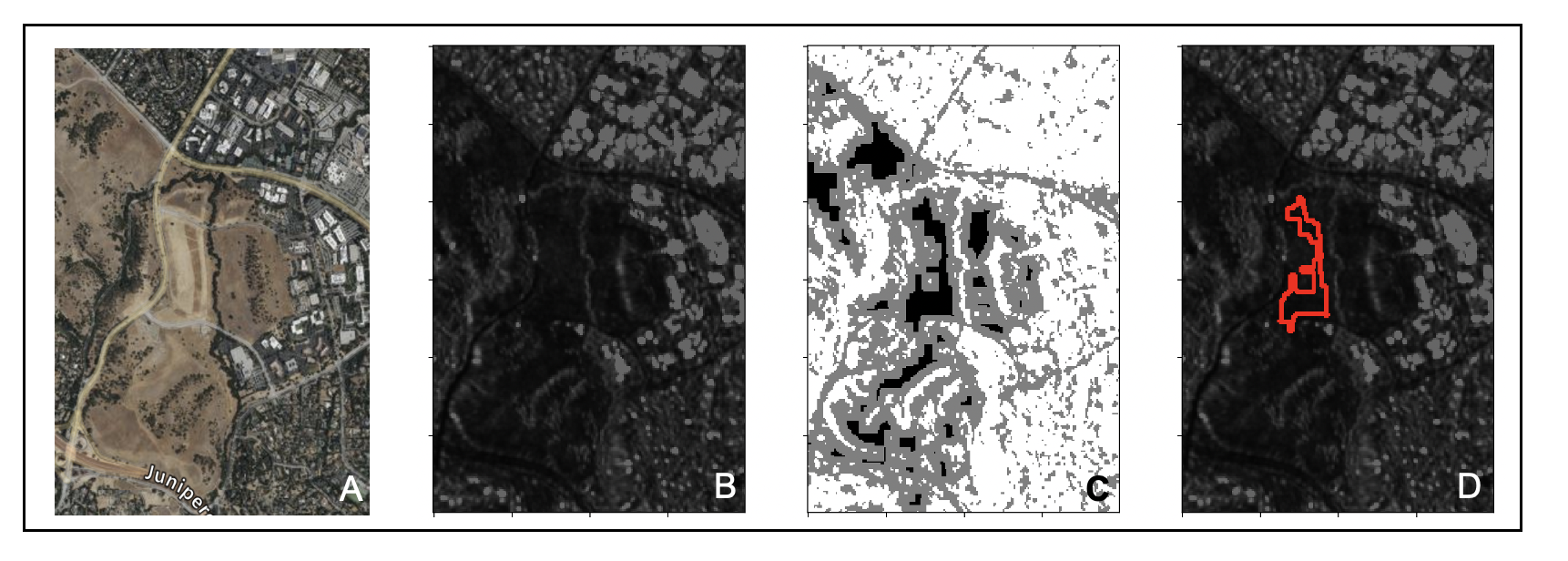
The first step of the algorithm is to select the best deployment site. Choosing a deployment area within a specified region will depend on the time of year, as we have shown rain has a large impact on background clutter, and the orbit path of the satellite. The ”Find Low Clutter” algorithm selects the best site to place a reflector based on the historical SAR data of the location and allows the user to choose a time frame over which to analyze, as well as which relative orbit to optimize deployment. The process of analyzing SAR images for low clutter areas and selecting deployment locations is illustrated in Figure 6 and summarized by Algorithm 1 below:
The algorithm first averages all the Sentinel-1 datasets that meet the specified input parameters. Looking at the camera image in Figure 6A and comparing it to the average of the previous SAR passes in 6B reveals that the grassy field has much less clutter than the man-made objects surrounding it. Next, the averaged image, f(x,y) is converted to a binary representation, g(x,y), using the threshold value , and shown in Equation 3. The threshold value is chosen based on the size of the reflector being deployed and the required SCR.
| (3) |
Next, an erosion algorithm is applied to the binary image, g(x,y), to find specified areas (kernels) that are not only low clutter in of themselves but are also surrounded by neighbors with low clutter.
This is summarized in Equation 4:
| (4) |
The results of both threshold and erosion are shown in Figure 6C, which shows g(x,y) + h(x,y). This operation results in an image where white pixels are locations above the threshold value, gray pixels are at locations that were eroded, meaning they were low clutter but too close to high clutter areas, and black pixels at locations that are both low clutter and surrounded by low clutter. Finally, in Figure 6D, the largest low clutter area is annotated on the Average SAR image to recommend a deployment location within the specified area. This is chosen by finding the contours within the eroded image and selecting the one with the maximum area. Contours are continuous curves joining areas in a binary image.
Once an ideal location is determined by the low clutter algorithm, the optimal bearing, as shown in Figure 7A, and tilt angle, shown in Figure 7B, can be selected. As mentioned above, the boresight of the reflector must be facing toward the satellite and aligned with the incidence angle of the incoming SAR signals. To determine the bearing, the relative orbit of the satellite is used to calculate the cardinal direction that the reflector should face. The algorithm outputs angles between 0 and 359°, with zero degrees being due north. This matches how any compass, such as those available on smartphones, presents angles. Similarly, the range location of the chosen deployment site within the imaging swath is used to determine what the incidence angle of the SAR signals will be and, therefore, how the reflector should be tilted. The tilt is calculated by subtracting the incidence and boresight angles, 35.26° from 90°. Guided with knowledge of where low-clutter locations are and their respective ideal bearing direction and tilt angles, corner reflectors can be deployed to optimize their SCR for communication.
4.2. Modulated Corner Reflectors
To modulate the SAR signal, the brightness of a target can be switched from highly reflective (ON) to non-reflective (OFF). In other words, data can be transmitted by enabling ON-OFF keying. As initial prototypes of the system, we built two smart targets that can switch between these two states either mechanically or electronically. In our implementation, we use corner reflectors as they have a large RCS. The mechanically and electronically modulated reflectors change their RCS by leveraging scattering and impedance-matching respectively. The mechanical design was also successful deployed in a real imaging scenario with Sentinel-1.
4.2.1. Mechanically Modulated Reflector
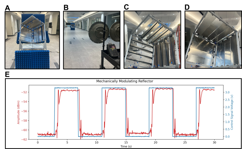
As corner reflectors are extremely sensitive to their panels’ angle, adjusting the alignment of the panels will scatter the incoming radar signal and reduce RCS dramatically. Each side of the corner reflector is divided into four panels, which are individually controlled by servos. The reflector was designed so that each side contains four sheets that form a 2x2 ft panel. To determine the difference in the RCS between the two states, we conduct a control experiment to measure the received signal strength of the backscattered signal for both ON and OFF states. Figure 8A-D shows the mechanically modulated corner reflector, the experimental setup, and the reflector in the two switching states. The reflector was placed 20 m away from a transmitter and receiver to ensure it was in the far field, and RF absorber foam was placed around it to reduce clutter (see Figure 8A). A USRP software-defined radio connected to a C-band antenna was used to transmit a continuous 5.75 GHz tone (in the ISM band and near Sentinel-1’s operation frequency), and the backscattered signal was received using a spectrum analyzer connected to an identical C-band antenna. The antennas were aligned with the reflector using a laser pointer such that the center of the antenna was pointing directly at the panels of the reflector. A control signal toggled the state of the corner reflector between its ON and OFF states roughly every 4 seconds. The reflector is shown in its OFF state in Figure 8C, and ON state in Figure 8D. The control signal (blue) and the power of the received backscatter signal (red) from the reflector are shown in Figure 8E. Using Equation 1, the expected RCS of an ideal 2 ft by 2 ft reflector at boresight is 1800 m2. Using Equation 2, the expected received power would be -40 dBm. Therefore, there was 12 dB less power, which can be attributed to the difficulties in aligning the antennas, additional losses in the cabling, and imperfections due to the gaps and angles of the modulating panels. The plot shows an approximately 10 dB difference between the two states, which equates to a 10-times reduction in the RCS. Given that Sentinel-1 has a worst-case radiometric accuracy of 1 dB, the differences between these two states can be easily detectable by the radar (Agency, 2024b).
4.2.2. Electronically Modulated Reflector
Although the mechanically modulated reflector described in Section 4.2.1 provides good contrast between its two states, it toggles too slowly to operate within the roughly 2.75 seconds window that Sentinel-1 typically scans each area for (Online, 2024), and the high power consumption of its servo motors also makes the device impractical for low-power systems. As such, we prototyped an electronically modulated version of the corner reflector to improve switching speed and decrease power consumption. Since Sentinel-1 measures backscatter signals, the power of the return signal can be modulated by impedance matching to either absorb (match) or reflect (mismatch) the signal from the satellite.
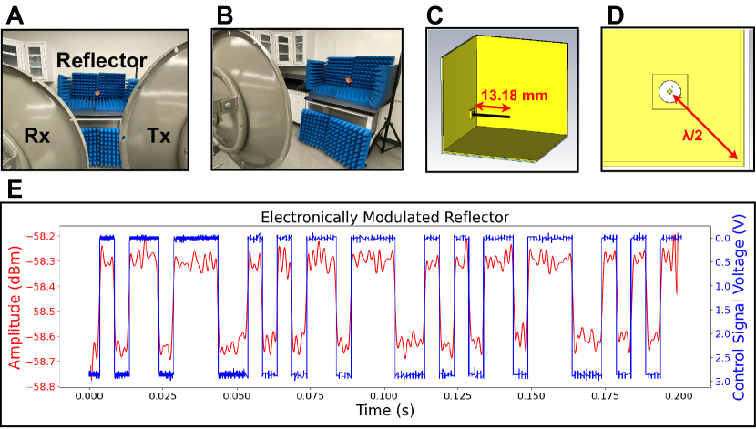
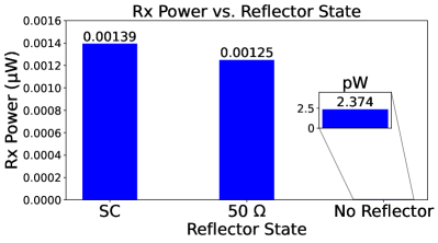
Corner reflectors are constantly in a reflective state, so to reduce their RCS an additional element must be added to absorb the signal that backscatter. In the design described in Figure 9C and 9D, we integrated a monopole feed into the corner reflector, which absorbs the TX signal when the feed impedance is matched with its load. The monopole antenna was designed in Ansys HFSS (Ansys, 2024) to have a simulated impedance of 50 at 5.4 GHz with a length of 13.18 mm and a diameter of 0.511 mm. It is also located half a wavelength away from the inside corner of the reflector (Kraus, 1940). The rest of the bench-scale reflector consists of three 70 mm by 70 mm FR4 sheets with copper plating on the inside. The copper plates are soldered together and connected to ground, while the feed is switched between either a 50 or short-circuit terminator by an Analog Devices ADG919EBZ switch (Devices, 2024). The background of the electronically modulated reflector is lined with RF absorber foam, and the rest of the setup is identical to the one described in Section 4.2.1 with the TX and RX antennas placed closer to the reflector to compensate for its smaller size (see Figure 9A and 9B). The contrast in RX power between the reflector states and the background clutter with no reflector can be seen in Figure 10.
In Figure 9E, the reflector passively modulates the reflected TX signal at a bit rate of 200 bps, which is sufficient to transmit multiple bits over the course of a satellite pass. The amplitude difference between the ON and OFF states from the electronically modulated corner reflector is less pronounced than its mechanical counterpart but this can likely be improved using a larger reflector size and a better-matched antenna since the TX frequency transmitted in the experiment was 5.75 GHz instead of the 5.4 GHz the antenna was tuned to. The only power requirement of the device comes from the ADG919EBZ (¡2 µW), therefore it can function with orders of magnitude less power than even the lowest-power IoT satellite solutions that use active TX transmissions (SWARM, 2023). This makes modulating reflectivity with impedance matching a promising approach to achieving passive ground-to-satellite communication.
4.3. SAR Processing for Communication
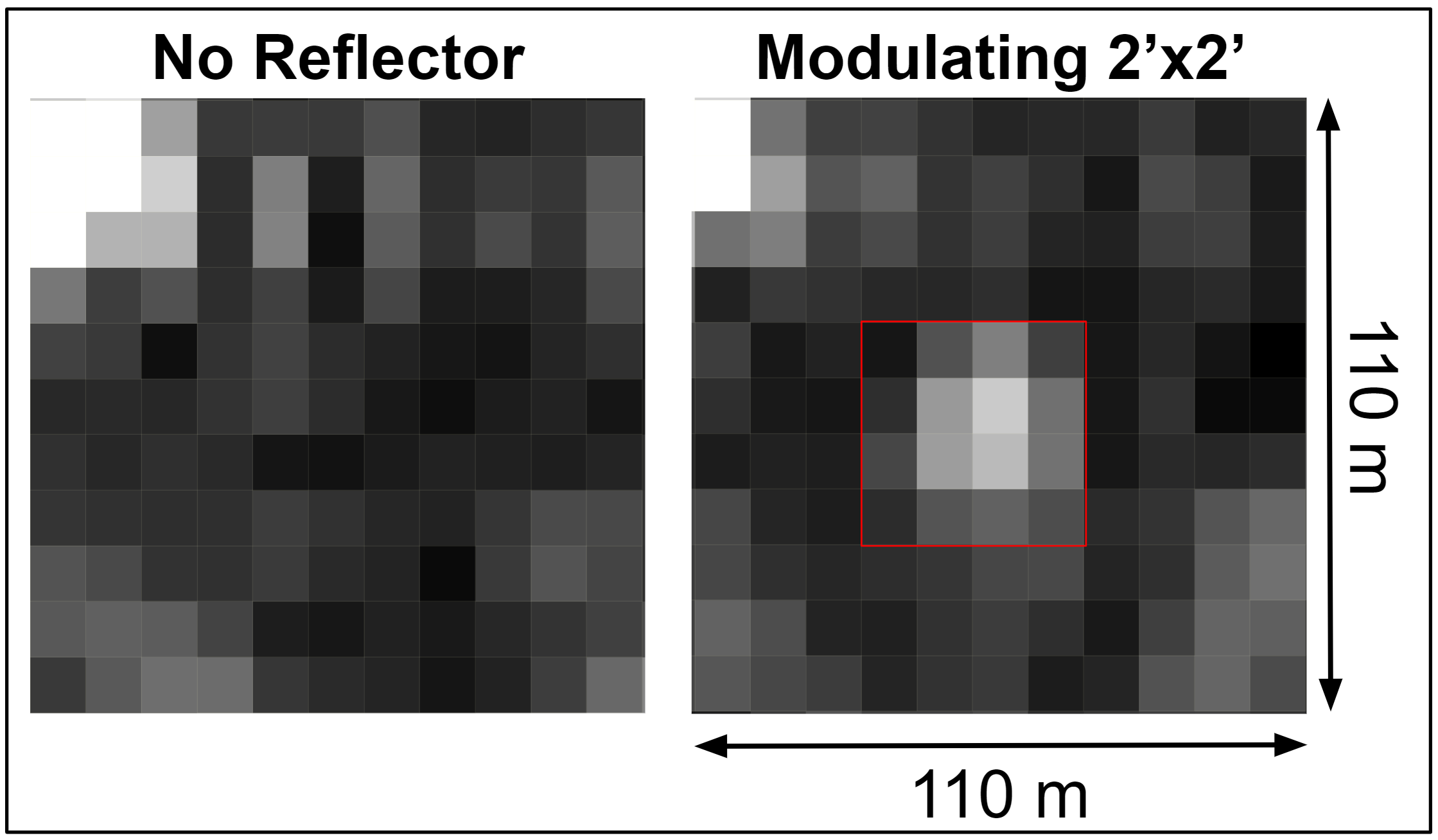
The aim of typical SAR processing is to produce an image with high resolution and it does so by sending many pulses over the same location as it passes overhead, whereas the aim of communication is to maximize the data rate. In this system, that means maximizing the number of bits sent during the satellite’s pass. In the simplest realization of a SAR backscatter communication system, a target with two configurable brightness levels can be used to communicate a single bit of information every pass. This can also be done across multiple locations to linearly scale the amount of information sent. We have demonstrated this capability by deploying the modulating reflector in the field and showing that when it is placed on a field, it appears, and when it is removed, the signal disappears (see Figure 11).
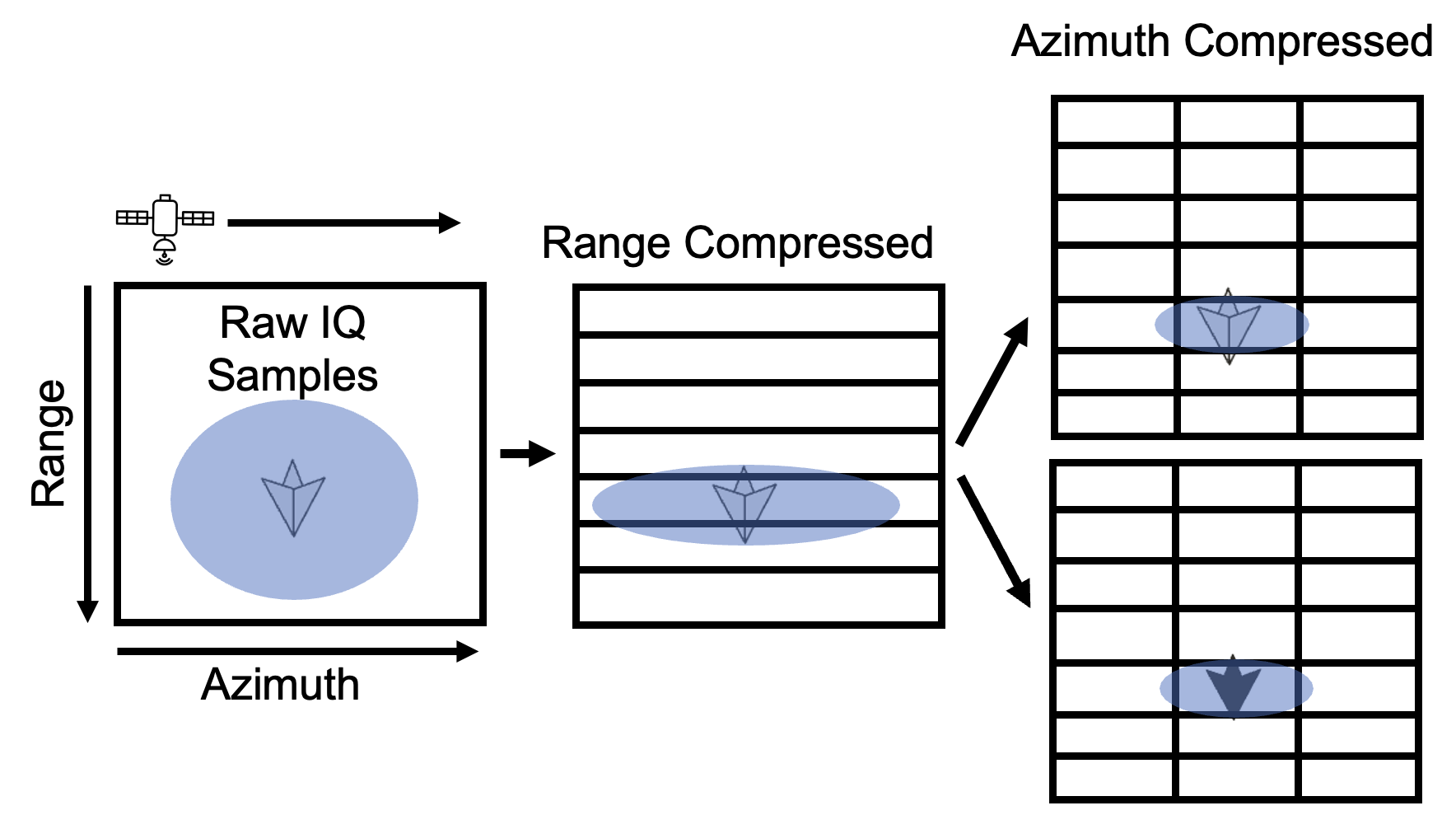
Sending more data from a single location every pass requires different processing techniques. Rather than forming a single image, sets of bursts can be analyzed separately, thus producing multiple independent images Figure 1. In this way, the reflector can be processed as ”on” or ”off” in separate ”sublooks” of the image. Since the synthetic aperture of the radar will effectively be cut into multiple pieces, the azimuth resolution of the sublook will be degraded by the number of sublooks generated. For example, Sentinel-1 has an azimuth resolution of 22 m in IW mode. If the image is split into two sublooks, this will increase the resolution to 44 m. If we split again, four images with azimuth resolutions of 88 m will be formed. Interestingly though, the range resolution will remain unaffected. In terms of data processing, this means that the data can be range compressed, and rather than doing full azimuth compression the remaining data can be processed in subsets to produce independent sublooks. Comparing Figure 3B to Figure 12 shows how the processing can be adapted for communication.
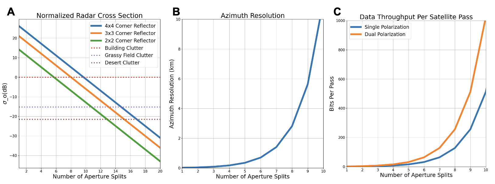
The extent to which an image can be split into sublooks will determine the number of bits that can be sent by the system in a single pass. To analyze the impact of splitting the synthetic aperture of the system, a theoretical model was developed and the key results are summarized in Figure 13A-C. As shown in Figure 13A the normalized radar cross section is shown for the corner reflector and several background clutter scenarios as the number of aperture splits is changed. The advantage of using a larger corner reflector or a less cluttered environment can be clearly seen as this improves the SCR. This plot also shows that each time the aperture is further split in two, the signal from the corner reflector will be degraded, while the background clutter remains the same. This is due to the fact that the reflector signal will be normalized over a larger area due to the increasing size of the resolution cells. This is caused by the reduction in azimuth resolution which is shown in Figure 13B. As the aperture is continually divided, the azimuth resolution quickly reaches several kilometers, which becomes impractical as there are other objects in the image that can start to average out the modulated brightness from the resolution cell. Figure 13C shows that each split of the aperture results in every previous image being split into two, and the number of bits that can be sent increases by a factor of 2 every time. So, the number of bits and azimuth resolution will increase at the same rate. The extent to which this azimuth resolution can be tolerated will depend on the SCR in the surrounding area and the size of the reflector. To deploy a functioning system these factors will need to be carefully balanced to achieve the successful processing of the data bits. This processing pipeline is the next step in employing this system and will be the focus of future work.
5. Related Work
This section describes prior work in IoT satellite connectivity as well as the use of corner reflectors for radar calibration and modulated reflective surfaces.
5.1. IoT Satellite Connectivity
The idea of connecting remote IoT devices to satellites has been well-explored by many commercial start-ups (SWARM, 2023; Starlink, 2023; Network, 2023). However, active radios that transmit enough power to communicate with satellites require many watts of power, which is orders of magnitude more than what typical energy-harvesting and battery-constrained systems could afford (Paradiso and Starner, 2005). Even state-of-the-art low-power satellite connectivity devices like Swarm M138 use upwards of 3.3 W during active transmission (SWARM, 2023), and the cost of these devices can also be substantial due to the use of private satellite networks. This makes developing passive, low-cost methods of communicating with open-sourced satellites such as Sentinel-1 motivating for the IoT community.
5.2. Corner Reflectors for Radar Calibration
In (Qin et al., 2013), they uniquely explored how one can design inexpensive corner reflectors to validate ground displacement data collected by Permanent Scatterers Interferometry Synthetic Aperture Radar (PSInSAR). In their work, the corner reflectors served as a tool to calibrate PSInSAR data from the TerraSAR-X satellite. A similar work that likewise uses static corner reflectors is (Czikhardt et al., 2022), which took the next step of using SAR time series and open-source Sentinel-1 (The European Space Agency, 2023) data to track reflector performance under highly variable environments. Since the reflectors deployed in both of these works are simple passive devices meant for establishing a ground truth, they cannot modulate their reflectivity for communication.
5.3. Modulated Reflective Surfaces
Other works that focused on military applications such as (Wang et al., 2019) provided insights into how one might construct an active surface that selectively absorbs RF waves of specific frequencies to perform SAR jamming. They were able to achieve amplitude modulation of backscattered SAR signal using an active frequency selective surface (AFSS) constructed from bow-tie antennas and PIN diodes. However, their processing and data collection methods used a stationary radar unit, which poses significantly fewer challenges than a moving satellite. This makes the concept of deploying similar modulated surfaces for ground-to-satellite communication interesting to explore.
6. Conclusion
This paper demonstrated that passive satellite connectivity can be enabled by modulating existing spaceborne SAR signals, particularly from Sentinel-1. Corner reflectors are an effective solution to achieve high radar cross-section, and modulating a corner reflector between highly reflective and non-reflective states can control backscatter amplitude to enable ground-to-satellite connectivity. While the early results of modulating SAR signals are promising, there several areas of future work that can lead to significant performance improvements:
-
•
Intelligent Smart Surfaces: The electronically modulating corner cube is able to function with power consumption and acheive the required throughput, but has a very large radar cross section and is not able to provide a large enough radar cross section. Therefore, future work will include different intelligent reflective surfaces which can be designed to modulate the SAR signals. Developing a smart surface like this would not only improve the performance of the existing technique but would also allow for the implementation of more sophisticated modulation techniques, beyond amplitude modulation.
-
•
Increasing Data Throughput: exploring the use of different polarization generation techniques could increase system capacity, or by simply using cross-polarization increase the SCR of the system. Additionally exploring how many reflectors can be placed next to each other to improve throughput that way can also be explored.
-
•
Satellite Backscatter Beyond SAR: Other satellites, such as radiometers, use RF signals and receivers that can be used for additional purposes. For example, radiometers could potentially be used for communication by changing the noise temperature of objects on the ground.
References
- (1)
- 80/20 (2024) 80/20. 2024. T-Slotted Profiles. https://8020.net/framing-options/t-slotted-profiles.html.
- Agency (2023a) European Space Agency. 2023a. About Space Debris. https://www.esa.int/Space_Safety/Space_Debris/About_space_debris.
- Agency (2023b) European Space Agency. 2023b. DataProdcuts. https://sentinels.copernicus.eu/web/sentinel/missions/sentinel-1/data-products.
- Agency (2023c) European Space Agency. 2023c. Mission Navigator. https://www.esa.int/ESA/Our_Missions.
- Agency (2024a) European Space Agency. 2024a. Interferometric Wide Swath. https://sentinels.copernicus.eu/web/sentinel/user-guides/sentinel-1-sar/acquisition-modes/interferometric-wide-swath.
- Agency (2024b) European Space Agency. 2024b. Performance. https://sentinel.esa.int/web/sentinel/technical-guides/sentinel-1-sar/sar-instrument/performance.
- Agency (2024c) The European Space Agency. 2024c. Sentinel Application Platform. https://earth.esa.int/eogateway/tools/snap.
- Ansys (2024) Ansys. 2024. Ansys HFSS. https://www.ansys.com/products/electronics/ansys-hfss.
- Culler et al. (2023) Marc Culler, Nathan M. Dunfield, Matthias Goerner, and Jeffrey R. Weeks. 2023. SnapPy, a computer program for studying the geometry and topology of -manifolds. Available at http://snappy.computop.org (DD/MM/YYYY).
- Czikhardt et al. (2021) Richard Czikhardt, Hans Van Der Marel, and Juraj Papco. 2021. GECORIS: An Open-Source Toolbox for Analyzing Time Series of Corner Reflectors in InSAR Geodesy. Remote Sensing 13, 5 (2021), 926. https://doi.org/10.3390/rs13050926
- Czikhardt et al. (2022) Richard Czikhardt, Hans van der Marel, Freek J. van Leijen, and Ramon F. Hanssen. 2022. Estimating Signal-to-Clutter Ratio of InSAR Corner Reflectors From SAR Time Series. IEEE Geoscience and Remote Sensing Letters 19 (2022), 1–5. https://doi.org/10.1109/LGRS.2021.3070045
- Devices (2024) Analog Devices. 2024. ADG919. https://www.analog.com/en/products/adg919.html.
- Friedt (2021) Jean-Michel Friedt. 2021. Sentinel-1 Level 0 Decoding Package. https://github.com/jmfriedt/sentinel1_level0.
- Gisinger et al. (2021) Christoph Gisinger, Adrian Schubert, Helko Breit, Matthew Garthwaite, Ulrich Balss, Martin Willberg, David Small, Michael Eineder, and Nuno Miranda. 2021. In-Depth Verification of Sentinel-1 and TerraSAR-X Geolocation Accuracy Using the Australian Corner Reflector Array. IEEE Transactions on Geoscience and Remote Sensing 59, 2 (2021), 1154–1181. https://doi.org/10.1109/TGRS.2019.2961248
- Kraus (1940) John D Kraus. 1940. The corner-reflector antenna. Proceedings of the IRE 28, 11 (1940), 513–519.
- Nations (2021) United Nations. 2021. ITU: 2.9 billion people still offline. https://www.un.org/en/delegate/itu-29-billion-people-still-offline.
- Network (2023) Hubble Network. 2023. Hubble Network. https://hubblenetwork.com/.
- Observatory (2023) National Radio Astronomy Observatory. 2023. Radio Frequency Interference. https://public.nrao.edu/telescopes/radio-frequency-interference/.
- of Alaska Fairbanks (2024) The University of Alaska Fairbanks. 2024. Alaska Satellite Facility. https://asf.alaska.edu/.
- of the Naval Warfare Center Weapons Division (2013) Avionics Department of the Naval Warfare Center Weapons Division. 2013. Electronics Warfare and Radar Systems Engineering Handbook. https://apps.dtic.mil/sti/tr/pdf/ADA617071.pdf.
- Office (2022) United States Government Accountability Office. 2022. Large Constellations of Satellites: Mitigating Environmental and Other Effects.
- Online (2024) Sentinel Online. 2024. Level-1. https://sentinels.copernicus.eu/web/sentinel/user-guides/sentinel-1-sar/product-types-processing-levels/level-1.
- Paradiso and Starner (2005) Joseph A Paradiso and Thad Starner. 2005. Energy scavenging for mobile and wireless electronics. IEEE Pervasive computing 4, 1 (2005), 18–27.
- Qin et al. (2013) Yuxiao Qin, Daniele Perissin, Ling Lei, et al. 2013. The design and experiments on corner reflectors for urban ground deformation monitoring in Hong Kong. International Journal of Antennas and Propagation 2013 (2013), 8 pages.
- Source et al. (2022) Microsoft Open Source, Matt McFarland, Rob Emanuele, Dan Morris, and Tom Augspurger. 2022. microsoft/PlanetaryComputer: October 2022. https://doi.org/10.5281/zenodo.7261897
- Starlink (2023) Starlink. 2023. Technology. https://www.starlink.com/technology.
- SWARM (2023) SWARM. 2023. Swarm Modem Product Manual. https://swarm.space/wp-content/uploads/2022/09/Swarm-M138-Modem-Product-Manual.pdf.
- The European Space Agency (2023) The European Space Agency. 2023. Introducing Sentinel-1. https://www.esa.int/Applications/Observing_the_Earth/Copernicus/Sentinel-1/Introducing_Sentinel-1.
- Wang et al. (2019) Junjie Wang, Dejun Feng, Letao Xu, Ran Zhang, and Weidong Hu. 2019. Synthetic Aperture Radar Target Feature Modulation Using Active Frequency Selective Surface. IEEE Sensors Journal 19, 6 (2019), 2113–2125. https://doi.org/10.1109/JSEN.2018.2886013
- Yang et al. (2023) Xiaoying Yang, Jacob Sayono, and Yang Zhang. 2023. CubeSense++: Smart Environment Sensing with Interaction-Powered Corner Reflector Mechanisms. In Proceedings of the 36th Annual ACM Symposium on User Interface Software and Technology (, San Francisco, CA, USA,) (UIST ’23). Association for Computing Machinery, New York, NY, USA, Article 78, 12 pages. https://doi.org/10.1145/3586183.3606744