Signatures of a surface spin-orbital chiral metal
Abstract
The relation between crystal symmetries, electron correlations, and electronic structure steers the formation of a large array of unconventional phases of matter, including magneto-electric loop currents and chiral magnetism [1, 2, 3, 4, 5, 6]. Detection of such hidden orders is a major goal in condensed matter physics. However, to date, nonstandard forms of magnetism with chiral electronic ordering have been experimentally elusive [7]. Here, we develop a theory for symmetry-broken chiral ground states and propose a methodology based on circularly polarized spin-selective angular-resolved photoelectron spectroscopy to probe them. We exploit the archetypal quantum material Sr2RuO4 and reveal spectroscopic signatures which, even though subtle, may be reconciled with the formation of spin-orbital chiral currents at the material surface [8, 9, 10]. As we shed light on these chiral regimes, our findings pave the way for a deeper understanding of ordering phenomena and unconventional magnetism.
Main
One central problem in condensed matter physics is the existence of unconventional magnetism
beyond the traditional forms, arising from the long-range order of magnetic dipole moments , with and being the electron spin and orbital angular momentum, respectively [11, 12, 13, 14, 15]. Most often, such magnetic dipole moments do not arrange spatially with ordered patterns in the crystal but other forms of magnetic phases may still originate from an electronic ordering made of charge currents at the atomic scale.
Such phases are odd in time (time-reversal symmetry is broken), inherently subtle and difficult to observe, and often associated with a hidden magnetic order [1, 16, 2].
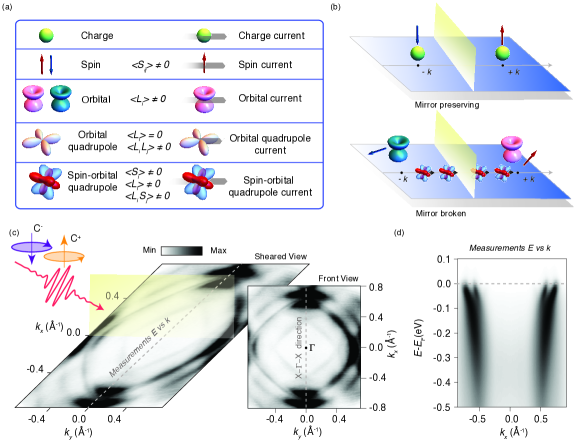
The transport properties of all metallic quantum materials are determined by the spin and orbital degrees of freedom of the Fermi surface. Broken symmetry states (mirror and/or time) with charge currents can have an internal structure with a combination of spin and orbital angular momentum. Since the spin and orbital angular momentum are pseudovectors with magnetic dipolar nature, one can refer to their product as a spin-orbital quadrupole or orbital quadrupole. Spin and orbital angular momentum are odd in time and the current is an odd function of crystal wave vector. Therefore, currents carrying spin-orbital or orbital quadrupoles, which are even in time, break time-reversal symmetry (Fig.1a) [8, 17, 18, 19].
A hallmark of both orbital and spin-orbital quadrupole current is the appearance of additional symmetry breaking related to mirror, inversion, or roto-inversion transformations, more generically known as chirality. Hence, a chiral electronic ordering may be realized uniquely as a consequence of the intrinsic spin and orbital structure of the charge currents [20, 21, 22]. Chirality is known to set out several unconventional forms of transport and magnetism [2, 23, 24, 25, 26, 27, 28]. However, chiral effects have been proven challenging to be detected, because their electronic signature is very weak. So far, their measurements are limited to only a few material-specific cases [1, 29, 30, 31].
In a metallic state, chiral orders imprint themselves on the spin and orbital textures of the electronic states close to the Fermi level [32, 33, 34]. The action of mirror- and time-reversal symmetries connects the amplitude of spin- and orbital-angular momentum of the electron states at symmetry-related momenta. For instance, for time-reversal symmetric electronic states (Fig.1b), the associated spin-angular momentum must have opposite orientations, i.e. transforms into [35]. The same behaviour applies to the orbital-angular momentum . On the other hand, for mirror-symmetric electronic states, due to the axial nature of and , upon mirror transformation the components lying within the mirror plane change sign, while the ones perpendicular to the plane remain unchanged. Apart from the dipolar one, the interaction between spin and orbital degrees of freedom can set out physical observables with tensorial character. Here, the time-reversal and mirror symmetries are also expected to affect the behavior of the spin-orbital () and orbital () quadrupole components, when probed at symmetry-related momenta. This means that the spin-orbital dipolar and quadrupolar structures are the relevant observables of the onset of a symmetry breaking and can be exploited to assess the nature of the realized electronic ordering. For a ground state hosting chiral currents, there is an antisymmetric combination of and . In this situation, the spin-orbital texture of the electronic states at the Fermi level exhibit a distinctive behavior: Chiral currents carrying spin-orbital quadrupoles give rise to orbital moments with the same parity as for mirror-symmetric systems, while spin-orbital quadrupoles themselves show neither a time nor mirror-symmetric profile. It is this physical case, that we focus on in this work.
To exemplify the concept of a chiral metal, one can employ the analogy with chiral crystals and their symmetry properties. One can then generally identify a chiral metal with an electronic state that has a well-defined handedness, due to the lack of inversion, mirror or other roto-inversion symmetries [36, 37]. In this study, we start from this description to introduce the concept of surface spin-orbital chiral metal to indicate a conducting electronic state of matter that has a well-defined handedness due to an interaction driven by magnetochiral order that lacks mirror symmetries, resulting from the internal spin-orbital structure, but possesses the same translational symmetry as the hosting crystal.
Here, we show the relationship between the spin-orbital textures of the electronic states, for both dipolar and quadrupolar channels, and the consequential occurrence of a chiral electronic ordering. By supporting the theory with circularly polarized spin-selective angular-resolved photoelectron spectroscopy, we introduce a methodology to probe, otherwise elusive,
symmetry-broken chiral electronic states.
To this aim, we exploit the archetypal quantum material Sr2RuO4 (see Methods for growth and measurements details) and reveal signatures of a broken symmetry phase [8], compatible with the formation of spin-orbital quadrupole currents at the material surface.
Dichroic and spin-dichroic photoemission effects
As anticipated, assessing whether the profile of the quadrupole components has a mirror-and time-broken character is key for the detection of electronic phases with electronic chiral currents.
Sr2RuO4 is an ideal candidate to host symmetry-broken chiral ground states because of the recent low-energy muon spin spectroscopy [8] and scanning tunnelling microscopy (STM) measurements [38], which unveil the existence of unconventional magnetism and electronic ordering forming at the surface.
To date, nevertheless, there are no accepted methodologies to ascertain the existence of such symmetry-broken chiral states. From our theory, in order to detect the action of symmetries on , one has to probe the out-of-plane components of the orbital angular-momentum () and spin (). Experimentally, the asymmetry can be tackled by circularly polarized spin-selective angular-resolved photoelectron spectroscopy (CP-Spin-ARPES) [35, 39]. This approach requires extreme caution in the alignment and geometry of the apparatus (Fig.1c). Indeed, photoelectrons from circularly polarized light host a combination of intrinsic and geometric matrix elements [40, 41]. Nevertheless, as shown in Ref.[41], these can be disentangled (see Methods).
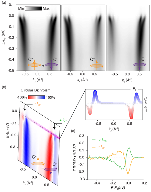
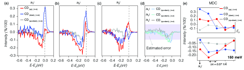
In Fig.2a, we show ARPES spectra collected in the geometry of Fig.1c, compatible with signals coming from both the bulk and surface states. The latter appear weaker in spectral intensity but clearly visible with increased contrast (see Methods). From left to right, in Fig.2a, spectra with unpolarized, right-, and left-circularly polarized photons are shown. The former shows an overall symmetric intensity pattern between features at and at . From these spectra, the circular dichroism () is extracted (Fig.2b), and the signal goes to at opposite momenta, consistent with previous studies [42]. This behaviour is also seen in the momentum-distribution curve (MDC) at the Fermi level (see the inset extracted along the mauve line). Importantly, an attentive look at the spin-integrated circular dichroism of Fig.2b reveals a small asymmetry in the residual of the amplitudes (see Methods Figures 9-10), quantified as large as 10. This value is slightly larger than the estimated experimental error on the dichroism for this experimental setup (around 8). In addition, there might be a component of asymmetry related to the character of the chiral electronic ordering (discussed in Supplementary Information). However, such an asymmetry remains significantly smaller than the one measured for spin-resolved signals. For completeness, spin-integrated data are collected with the VLEED spin detector (Fig.2c at two points) and show the same behaviour.
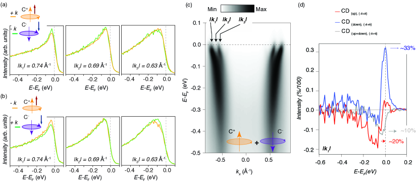
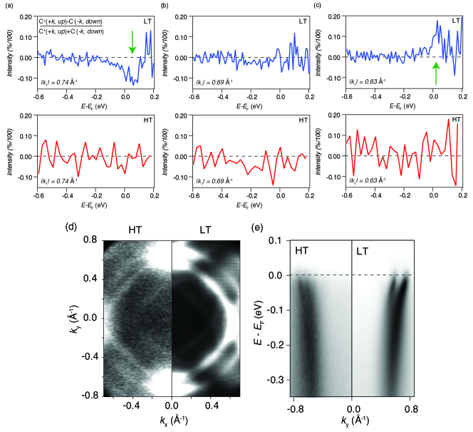
Importantly, the spin-integrated data of Fig.2c are not only consistent with other ARPES works, but also, they do not reveal mirror-symmetry breaking relatable to an anomalous behavior of . On the other hand, quantities such as spin-orbital chiral currents, which strongly depend on the spin as much as on the orbital angular-momentum, cannot be imaged by standard circularly polarized ARPES. Here, we will refer to for indicating signals from right- (or left-) circularly polarized light, collected at momentum , and with a spin-up (or down) component, respectively. In a perfectly symmetry-preserving situation, the circularly-polarized spin-ARPES intensity transforms under the mirror operator, from to (or equivalently from to ). This means that and (or and ) are expected to be the same under mirror symmetry in the case that the latter is preserved [35]. However, if loop currents are present along the surface, the mirror symmetry is broken and these quantities are not equivalent anymore. This scenario is what we tested with CP-Spin-ARPES and reported in Fig.3a-b: we observe subtle differences at different points, as noted in Fig.3c, between and (or and ). These differences, despite being very small, result instead in a sizeable asymmetry in the amplitudes of spin-up and down dichroism (Fig.3d). Note that for the latter, positive and negative momenta have been summed, compensating for possible instrumental asymmetry of the measurements.
Such a mirror-symmetry breaking in the amplitude of the spin-dichroism seems compatible with the presence of spin-orbital quadrupole currents, as predicted by the theory. In addition to this, the finite dichroism difference observed experimentally is not seen for a temperature of 77 K, higher than the magnetic transition temperature as indicated by the muons spectroscopy [8], however, this requires further investigation as the thermal broadening becomes significantly more pronounced (see Methods). The important finding here, is that the estimated difference in spin from the dichroic signals is up to a factor of 3 times larger than the spin-integrated one . In Fig.3d, the amplitude of the spin-integrated dichroic signal is approximately 10 (grey curve), while the spin-resolved is as high as 20 for spin-up (red curve) and 30 for spin-down (blue curve); see Supplementary Information for possible explanation of the spin-integrated asymmetry observed. We emphasize that a quantitative analysis is difficult and the signals detected are subtle. To quantify these effects correctly, future measurements as a function of photon energy and various geometries will be desirable. Nevertheless, the presence of a sizeable asymmetry in the amplitude signal from and is observed and this is consistent with the theoretical predictions.
Chiral currents phase
We now analyze our experimental results from a theoretical point of view.
This can be done with a
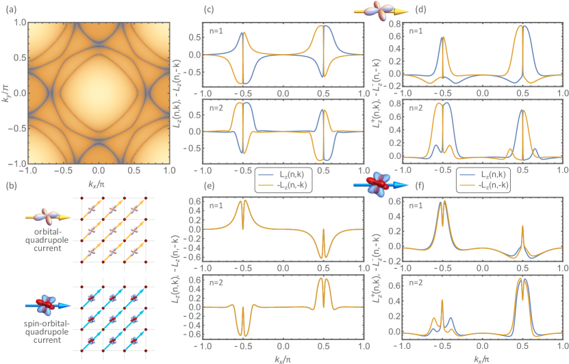
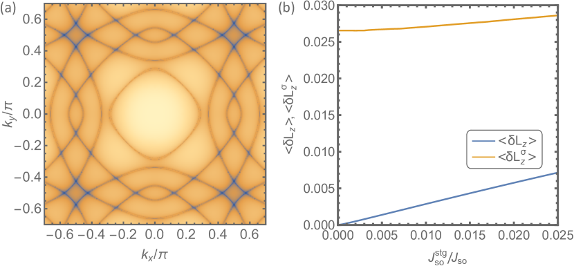
two-dimensional tight-binding description of the electronic structure of Sr2RuO4 based on the Ru -orbitals (,,) in such a way to capture the profile of the experimental Fermi surface (Fig.4a). In this model, we include the broken symmetry states hosting orbital and spin-orbital quadrupole currents that are driven by the Coulomb interactions (see Supplementary Information for details).
The internal structure of the charge currents is provided by either the orbital quadrupole or by the spin-orbital quadrupole tensors (see also Fig.1a for differences between these currents). For a given direction in momentum space, the amplitude of the charge current propagating through the lattice can in principle contain various components of the type and for the orbital and spin-orbital quadrupole, respectively (note that the first does not contain any spin channel, the second instead does).
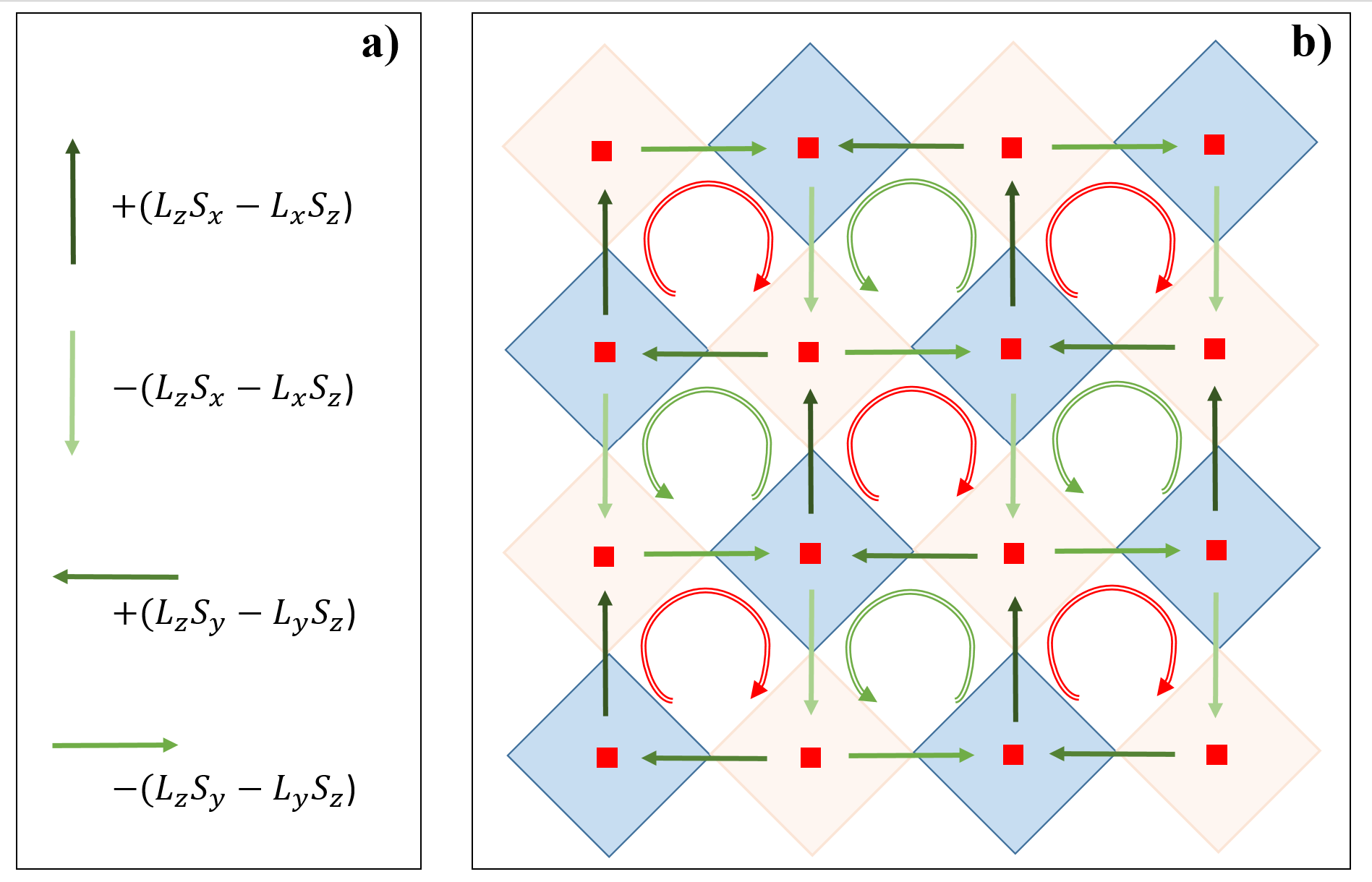
In the presence of currents flowing along e.g. that break all mirror symmetries (i.e. ), the orbital and spin-orbital quadrupoles have to include components with and that are perpendicular to , thus lying in the planes. For instance, a term of the type does not preserve the mirror symmetry for any choice of the transformations. The latter is exactly the case of Sr2RuO4, where a uniform charge current flows with the direction of the momentum aligned along the direction of the Ru lattice (see Fig. 4b). This pattern is compatible with symmetry-allowed loop currents involving charge current flowing from ruthenium to oxygen atoms at the octahedra length scale [8].
The qualitative outcomes of the results are not altered by surface reconstruction or by having currents flowing along other symmetry directions (see Supplementary Information for details).
We select a spin-orbital chiral state that breaks the rotational symmetry because it is compatible with the scanning tunnelling microscopy findings [38].
However, spin-orbital chiral states with loop currents that are rotational invariant can be also constructed. They break translational symmetry and do not modify the qualitative outcomes of the analysis (see Supplementary Information).
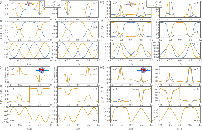
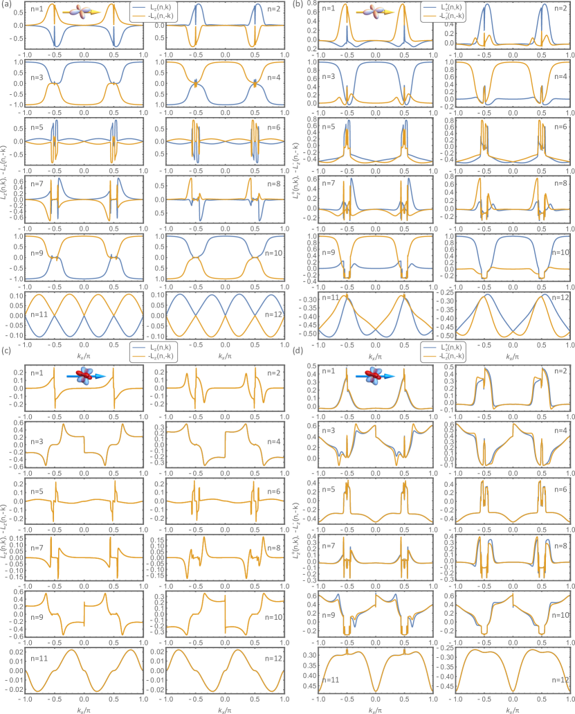
Additionally, the charge current along [110] is directly relevant when probing the electronic states along the corresponding direction of the Brillouin zone (along -X as in our experiment). To evaluate the orbital and spin-orbital textures for the electronic states in the presence of either orbital or spin-orbital quadrupole currents, we will focus on such direction. For each band eigenstate at a given momentum , we determine the amplitude of the out-of-plane orbital moment and the spin-projected orbital moment (i.e. the out-of-plane spin-up () and down () components as singled out by the projector ). These observables are related to the dichroic and spin-dichroic amplitudes probed by ARPES, respectively (see Supplementary Information for details). For clarity and simplicity, we display only two representative bands, e.g. (the behavior for the other bands is however qualitatively similar and reported in Supplementary Information). As shown in Fig.4c, a broken symmetry state with orbital quadrupole currents exhibits an asymmetry in the orbital angular moment at opposite momenta, i.e. . Moreover, both the amplitude and the sign of and are dissimilar (Fig.4d). Instead, for spin-orbital currents (Fig.4b) with an antisymmetric combination of and , i.e. , we find that the orbital angular momentum turns out to be antisymmetric at and , namely (Fig.4e), while the spin-projected orbital moment does not exhibit any symmetry relation among the states at opposite momentum (Fig.4f). Importantly, the last asymmetry is the same observed experimentally by the CP-Spin-ARPES. One way to grasp the origin of this behavior is to inspect the structure of the equations of motion for the amplitudes of the orbital and spin moments (see Supplementary Information for details). The chiral currents lead to spin-orbital torques that in the case of the spin-orbital quadrupole current result into a balance such as the amplitude of the orbital moment has a symmetric behavior at symmetry-related momenta.
Additionally, we have also addressed the role of sublattice chiral currents due to the surface reconstruction resulting from the octahedral rotations (see Supplementary Information).
When we consider an inhomogeneous state with a staggered amplitude modulation of the currents, we find that a small asymmetry of the orbital moment is obtained. Nevertheless, its amplitude is substantially smaller than that of the spin-projected orbital moment (see Supplementary Information). This implies that non-homogeneous chiral currents are also compatible with the observation of a much larger spin-dichroic asymmetry as compared to the dichroic one.
This behavior holds independently of the selected band and momentum, differently from that of magnetic states, e.g. antiferromagnetic, with a pattern in the spin and orbital moments that break time and mirror symmetries (see Supplemental Information).
Conclusions
In conclusion, we discovered a spin-orbital and angular-momentum sensitive methodology based on CP-Spin-ARPES, able to probe symmetry breaking compatible with the existence of spin-orbital chiral currents. While the study has been applied to the archetypal Sr2RuO4, this methodology is general to all chiral surface metals and constitutes a tantalizing experimental avenue to detect symmetry-broken chiral states.
However, since the effect is subtle one cannot exclude that the observed symmetry breaking might arise from other real space chiral orderings that break both time and mirror symmetries. Nevertheless, our work stimulates the combined use of circular dichroism and spin-selective photoemission to investigate how all three quantities , , and behave and their relationship to the crystal symmetries, which are markers for hidden ordered phases.
The spin-dichroic signal we have used to detect the putative presence of quadrupole spin-orbital currents at the surface of Sr2RuO4 can be used without restrictions in other quantum materials, even when currents appear in the bulk of a (centrosymmetric) crystal. In this situation, the currents might preserve the combination of time-reversal with inversion symmetry, with the consequent absence of dichroism. Nevertheless, the asymmetry of the spin-dichroic signal could be still visible and therefore represents an efficient diagnostic tool for spin-orbital chiral metallic phases.
References
- Xu et al. [2022] Y. Xu, Z. Ni, Y. Liu, B. R. Ortiz, Q. Deng, S. D. Wilson, B. Yan, L. Balents, and L. Wu, Three-state nematicity and magneto-optical Kerr effect in the charge density waves in kagome superconductors, Nature Physics 18, 1470 (2022).
- Grytsiuk et al. [2020] S. Grytsiuk, J. P. Hanke, M. Hoffmann, J. Bouaziz, O. Gomonay, G. Bihlmayer, S. Lounis, Y. Mokrousov, and S. Blügel, Topological–chiral magnetic interactions driven by emergent orbital magnetism, Nature Communications 11, 511 (2020).
- Zhang et al. [2022] Y. Zhang, Y. Ni, H. Zhao, S. Hakani, F. Ye, L. DeLong, I. Kimchi, and G. Cao, Control of chiral orbital currents in a colossal magnetoresistance material, Nature 611, 467 (2022).
- Barron [2000] L. D. Barron, Chirality, magnetism and light, Nature 405, 895 (2000).
- Bode et al. [2007] M. Bode, M. Heide, K. von Bergmann, P. Ferriani, S. Heinze, G. Bihlmayer, A. Kubetzka, O. Pietzsch, S. Blügel, and R. Wiesendanger, Chiral magnetic order at surfaces driven by inversion asymmetry, Nature 447, 190 (2007).
- Cheong and Xu [2022] S.-W. Cheong and X. Xu, Magnetic chirality, npj Quantum Materials 7, 40 (2022).
- Guo et al. [2022] C. Guo, C. Putzke, S. Konyzheva, X. Huang, M. Gutierrez-Amigo, I. Errea, D. Chen, M. G. Vergniory, C. Felser, M. H. Fischer, T. Neupert, and P. J. W. Moll, Switchable chiral transport in charge-ordered kagome metal CsV3Sb5, Nature 611, 461 (2022).
- Fittipaldi et al. [2021] R. Fittipaldi, R. Hartmann, M. T. Mercaldo, S. Komori, A. Bjørlig, W. Kyung, Y. Yasui, T. Miyoshi, L. A. B. Olde Olthof, C. M. Palomares Garcia, V. Granata, I. Keren, W. Higemoto, A. Suter, T. Prokscha, A. Romano, C. Noce, C. Kim, Y. Maeno, E. Scheer, B. Kalisky, J. W. A. Robinson, M. Cuoco, Z. Salman, A. Vecchione, and A. Di Bernardo, Unveiling unconventional magnetism at the surface of Sr2RuO4, Nature Communications 12, 5792 (2021).
- Imai et al. [1998] T. Imai, A. W. Hunt, K. R. Thurber, and F. C. Chou, 17O NMR evidence for orbital dependent ferromagnetic correlations in , Phys. Rev. Lett. 81, 3006 (1998).
- Grinenko et al. [2020] V. Grinenko, R. Sarkar, K. Kihou, C. H. Lee, I. Morozov, S. Aswartham, B. Büchner, P. Chekhonin, W. Skrotzki, K. Nenkov, R. Hühne, K. Nielsch, S. L. Drechsler, V. L. Vadimov, M. A. Silaev, P. A. Volkov, I. Eremin, H. Luetkens, and H. H. Klauss, Superconductivity with broken time-reversal symmetry inside a superconducting s-wave state, Nature Physics 16, 789 (2020).
- Mishra et al. [2020] S. Mishra, D. Beyer, K. Eimre, S. Kezilebieke, R. Berger, O. Gröning, C. A. Pignedoli, K. Müllen, P. Liljeroth, P. Ruffieux, X. Feng, and R. Fasel, Topological frustration induces unconventional magnetism in a nanographene, Nature Nanotechnology 15, 22 (2020).
- Kao et al. [2022] I.-H. Kao, R. Muzzio, H. Zhang, M. Zhu, J. Gobbo, S. Yuan, D. Weber, R. Rao, J. Li, J. H. Edgar, J. E. Goldberger, J. Yan, D. G. Mandrus, J. Hwang, R. Cheng, J. Katoch, and S. Singh, Deterministic switching of a perpendicularly polarized magnet using unconventional spin–orbit torques in WTe2, Nature Materials 21, 1029 (2022).
- Chu et al. [2012] J.-H. Chu, H.-H. Kuo, J. G. Analytis, and I. R. Fisher, Divergent nematic susceptibility in an iron arsenide superconductor, Science 337, 710 (2012).
- Wang et al. [2015] F. Wang, S. A. Kivelson, and D.-H. Lee, Nematicity and quantum paramagnetism in FeSe, Nature Physics 11, 959 (2015).
- Zhao et al. [2016] L. Zhao, D. H. Torchinsky, H. Chu, V. Ivanov, R. Lifshitz, R. Flint, T. Qi, G. Cao, and D. Hsieh, Evidence of an odd-parity hidden order in a spin–orbit coupled correlated iridate, Nature Physics 12, 32 (2016).
- Bounoua et al. [2020] D. Bounoua, L. Mangin-Thro, J. Jeong, R. Saint-Martin, L. Pinsard-Gaudart, Y. Sidis, and P. Bourges, Loop currents in two-leg ladder cuprates, Communications Physics 3, 123 (2020).
- Tang et al. [2023] N. Tang, Y. Gritsenko, K. Kimura, S. Bhattacharjee, A. Sakai, M. Fu, H. Takeda, H. Man, K. Sugawara, Y. Matsumoto, Y. Shimura, J. Wen, C. Broholm, H. Sawa, M. Takigawa, T. Sakakibara, S. Zherlitsyn, J. Wosnitza, R. Moessner, and S. Nakatsuji, Spin–orbital liquid state and liquid–gas metamagnetic transition on a pyrochlore lattice, Nature Physics 19, 92 (2023).
- Zapf et al. [2023] V. S. Zapf, M. Lee, and P. F. S. Rosa, Melted spin ice, Nature Physics 19, 17 (2023).
- Liu et al. [2019] F. Liu, H.-Y. Deng, and K. Wakabayashi, Helical topological edge states in a quadrupole phase, Phys. Rev. Lett. 122, 086804 (2019).
- Hasan et al. [2021] M. Z. Hasan, G. Chang, I. Belopolski, G. Bian, S.-Y. Xu, and J.-X. Yin, Weyl, Dirac and high-fold chiral fermions in topological quantum matter, Nature Reviews Materials 6, 784 (2021).
- Xin et al. [2020] T. Xin, Y. Li, Y.-a. Fan, X. Zhu, Y. Zhang, X. Nie, J. Li, Q. Liu, and D. Lu, Quantum phases of three-dimensional chiral topological insulators on a spin quantum simulator, Phys. Rev. Lett. 125, 090502 (2020).
- Chen et al. [2021] T. Chen, T. Tomita, S. Minami, M. Fu, T. Koretsune, M. Kitatani, I. Muhammad, D. Nishio-Hamane, R. Ishii, F. Ishii, R. Arita, and S. Nakatsuji, Anomalous transport due to Weyl fermions in the chiral antiferromagnets Mn3X, X = Sn, Ge, Nature Communications 12, 572 (2021).
- Avci et al. [2019] C. O. Avci, E. Rosenberg, L. Caretta, F. Büttner, M. Mann, C. Marcus, D. Bono, C. A. Ross, and G. S. D. Beach, Interface-driven chiral magnetism and current-driven domain walls in insulating magnetic garnets, Nature Nanotechnology 14, 561 (2019).
- Casher and Susskind [1974] A. Casher and L. Susskind, Chiral magnetism (or magnetohadrochironics), Phys. Rev. D 9, 436 (1974).
- Fukushima et al. [2008] K. Fukushima, D. E. Kharzeev, and H. J. Warringa, Chiral magnetic effect, Phys. Rev. D 78, 074033 (2008).
- Rikken and Avarvari [2022] G. L. J. A. Rikken and N. Avarvari, Dielectric magnetochiral anisotropy, Nature Communications 13, 3564 (2022).
- Legg et al. [2022] H. F. Legg, M. Rößler, F. Münning, D. Fan, O. Breunig, A. Bliesener, G. Lippertz, A. Uday, A. A. Taskin, D. Loss, J. Klinovaja, and Y. Ando, Giant magnetochiral anisotropy from quantum-confined surface states of topological insulator nanowires, Nature Nanotechnology 17, 696 (2022).
- Atzori et al. [2021] M. Atzori, C. Train, E. A. Hillard, N. Avarvari, and G. L. J. A. Rikken, Magneto-chiral anisotropy: From fundamentals to perspectives, Chirality 33, 844 (2021), https://onlinelibrary.wiley.com/doi/pdf/10.1002/chir.23361 .
- Barron [2008] L. D. Barron, Chirality and magnetism shake hands, Nature Materials 7, 691 (2008).
- Yang [2022] S.-H. Yang, Chirality tweaks spins in tellurium, Nature Materials 21, 494 (2022).
- Shekhar [2018] C. Shekhar, Chirality meets topology, Nature Materials 17, 953 (2018).
- Train et al. [2008] C. Train, R. Gheorghe, V. Krstic, L.-M. Chamoreau, N. S. Ovanesyan, G. L. J. A. Rikken, M. Gruselle, and M. Verdaguer, Strong magneto-chiral dichroism in enantiopure chiral ferromagnets, Nature Materials 7, 729 (2008).
- Ma et al. [2017] Q. Ma, S.-Y. Xu, C.-K. Chan, C.-L. Zhang, G. Chang, Y. Lin, W. Xie, T. Palacios, H. Lin, S. Jia, P. A. Lee, P. Jarillo-Herrero, and N. Gedik, Direct optical detection of Weyl fermion chirality in a topological semimetal, Nature Physics 13, 842 (2017).
- Li et al. [2016] Q. Li, D. E. Kharzeev, C. Zhang, Y. Huang, I. Pletikosić, A. V. Fedorov, R. D. Zhong, J. A. Schneeloch, G. D. Gu, and T. Valla, Chiral magnetic effect in ZrTe5, Nature Physics 12, 550 (2016).
- Schüler et al. [2020] M. Schüler, U. D. Giovannini, H. Hübener, A. Rubio, M. A. Sentef, and P. Werner, Local Berry curvature signatures in dichroic angle-resolved photoelectron spectroscopy from two-dimensional materials, Science Advances 6, eaay2730 (2020), https://www.science.org/doi/pdf/10.1126/sciadv.aay2730 .
- Moss [1996] G. P. Moss, Basic terminology of stereochemistry (IUPAC recommendations 1996), Pure and Applied Chemistry 68, 2193 (1996).
- Flack [2003] H. D. Flack, Chiral and achiral crystal structures, Helvetica Chimica Acta 86, 905 (2003), https://onlinelibrary.wiley.com/doi/pdf/10.1002/hlca.200390109 .
- Marques et al. [2021] C. A. Marques, L. C. Rhodes, R. Fittipaldi, V. Granata, C. M. Yim, R. Buzio, A. Gerbi, A. Vecchione, A. W. Rost, and P. Wahl, Magnetic-field tunable intertwined checkerboard charge order and nematicity in the surface layer of Sr2RuO4, Advanced Materials 33, 2100593 (2021).
- Di Sante et al. [2023] D. Di Sante, C. Bigi, P. Eck, S. Enzner, A. Consiglio, G. Pokharel, P. Carrara, P. Orgiani, V. Polewczyk, J. Fujii, P. D. C. King, I. Vobornik, G. Rossi, I. Zeljkovic, S. D. Wilson, R. Thomale, G. Sangiovanni, G. Panaccione, and F. Mazzola, Flat band separation and robust spin Berry curvature in bilayer kagome metals, Nature Physics 19, 1135–1142 (2023).
- Razzoli et al. [2017] E. Razzoli, T. Jaouen, M.-L. Mottas, B. Hildebrand, G. Monney, A. Pisoni, S. Muff, M. Fanciulli, N. C. Plumb, V. A. Rogalev, V. N. Strocov, J. Mesot, M. Shi, J. H. Dil, H. Beck, and P. Aebi, Selective probing of hidden spin-polarized states in inversion-symmetric bulk , Phys. Rev. Lett. 118, 086402 (2017).
- Cho et al. [2018] S. Cho, J.-H. Park, J. Hong, J. Jung, B. S. Kim, G. Han, W. Kyung, Y. Kim, S.-K. Mo, J. D. Denlinger, J. H. Shim, J. H. Han, C. Kim, and S. R. Park, Experimental observation of hidden Berry curvature in inversion-symmetric bulk , Phys. Rev. Lett. 121, 186401 (2018).
- Nelson et al. [2004] K. D. Nelson, Z. Q. Mao, Y. Maeno, and Y. Liu, Odd-parity superconductivity in Sr2RuO4, Science 306, 1151 (2004), https://www.science.org/doi/pdf/10.1126/science.1103881 .
- Fittipaldi et al. [2005] R. Fittipaldi, A. Vecchione, S. Fusanobori, K. Takizawa, H. Yaguchi, J. Hooper, R. Perry, and Y. Maeno, Crystal growth of the new Sr2RuO4–Sr3Ru2O7 eutectic system by a floating-zone method, Journal of Crystal Growth 282, 152 (2005).
- Bigi et al. [2021] C. Bigi, F. Mazzola, J. Fujii, I. Vobornik, G. Panaccione, and G. Rossi, Measuring spin-polarized electronic states of quantum materials: , Phys. Rev. B 103, 245142 (2021).
- Sunko et al. [2019] V. Sunko, E. Abarca Morales, I. Marković, M. E. Barber, D. Milosavljević, F. Mazzola, D. A. Sokolov, N. Kikugawa, C. Cacho, P. Dudin, H. Rosner, C. W. Hicks, P. D. C. King, and A. P. Mackenzie, Direct observation of a uniaxial stress-driven Lifshitz transition in Sr2RuO4, npj Quantum Materials 4, 46 (2019).
- Beaulieu et al. [2020] S. Beaulieu, J. Schusser, S. Dong, M. Schüler, T. Pincelli, M. Dendzik, J. Maklar, A. Neef, H. Ebert, K. Hricovini, M. Wolf, J. Braun, L. Rettig, J. Minár, and R. Ernstorfer, Revealing hidden orbital pseudospin texture with time-reversal dichroism in photoelectron angular distributions, Phys. Rev. Lett. 125, 216404 (2020).
- Scholz et al. [2013] M. R. Scholz, J. Sánchez-Barriga, J. Braun, D. Marchenko, A. Varykhalov, M. Lindroos, Y. J. Wang, H. Lin, A. Bansil, J. Minár, H. Ebert, A. Volykhov, L. V. Yashina, and O. Rader, Reversal of the circular dichroism in angle-resolved photoemission from , Phys. Rev. Lett. 110, 216801 (2013).
- Park et al. [2012] J.-H. Park, C. H. Kim, J.-W. Rhim, and J. H. Han, Orbital rashba effect and its detection by circular dichroism angle-resolved photoemission spectroscopy, Phys. Rev. B 85, 195401 (2012).
- Damascelli et al. [2000] A. Damascelli, D. H. Lu, K. M. Shen, N. P. Armitage, F. Ronning, D. L. Feng, C. Kim, Z.-X. Shen, T. Kimura, Y. Tokura, Z. Q. Mao, and Y. Maeno, Fermi surface, surface states, and surface reconstruction in , Phys. Rev. Lett. 85, 5194 (2000).
- Tamai et al. [2019] A. Tamai, M. Zingl, E. Rozbicki, E. Cappelli, S. Riccò, A. de la Torre, S. McKeown Walker, F. Y. Bruno, P. D. C. King, W. Meevasana, M. Shi, M. Radović, N. C. Plumb, A. S. Gibbs, A. P. Mackenzie, C. Berthod, H. U. R. Strand, M. Kim, A. Georges, and F. Baumberger, High-resolution photoemission on reveals correlation-enhanced effective spin-orbit coupling and dominantly local self-energies, Phys. Rev. X 9, 021048 (2019).
Methods
The samples of Sr2RuO4 were grown by floating zone technique, following the procedure of Ref.[1]. Single crystals were post-cleaved in ultrahigh vacuum at a base pressure of 1 mbar and at a temperature of K (and K). The latter was kept constant throughout the measurements. The experiment was performed at the NFFA-APE Low Energy beamline laboratory at the Elettra synchrotron radiation facility designed with an APPLE-II aperiodic source for polarized EUV radiation and a vectorial twin-VLEED spin polarization detector downstream of a DA30 Scienta ARPES analyser [2]. The photon energy used for our measurements was eV, which is found to maximize the spectral intensity, as also shown in Ref.[3]. The energy and momentum resolutions were better than meV and Å-1, respectively. Importantly, as already mentioned, we stress that in order to eliminate the geometrical contribution to the circular polarization, the crystals were aligned as in Fig.1c-d. For completeness, we report seminal works on ARPES and dichroism which might help the understanding of the measurements performed in our article, i.e., Ref.[4, 5, 6, 7, 8].
In this part of the Methods, we report additional measurements which contributes to corroborate the message and conclusions in the main text.
Sample alignment and experimental geometry
When using circularly polarized light, the disentanglement between geometrical and intrinsic matrix elements is crucial and challenging. A solution is to have the incoming radiation exactly within one of the mirror planes of the system studied and to measure in the direction orthogonal to that plane, as we show in Fig. 1c of the main text. In such a configuration, the differences in the CP-Spin-ARPES signal can be attributed to intrinsic differences in and the geometrical contributions are well-defined. In this regard, it is of paramount importance to align the sample very carefully. In the present case, the symmetric character of the material’s Fermi surface [9, 10, 3] allows us to carefully align the sample with the incoming beam of photons lying within a mirror plane. The alignment of the sample was carried out by monitoring the experimental Fermi surface and by making sure that the analyzer slit direction was perpendicular to the mirror plane. As one can see in Figs. 5 and 6, we estimated our alignment to be better than 0.9∘ from the ideal configuration, a value within the uncertainty considering our angular azimuthal precision (1∘). Furthermore, different samples mounted gave us the same results, corroborating the robustness of the measurements outputs within this azimuth uncertainty.
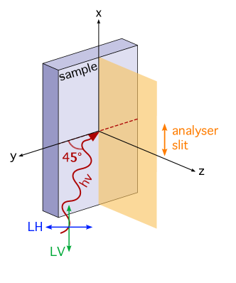
In the laboratory APE-LE, our sample is placed in the manipulator in normal emission conditions, with the synchrotron light impinging on the sample surface at 45∘ angle. This means that standard linear polarizations, such as linear vertical and linear horizontal (See Fig. 5), would act quite differently on the matrix elements selection rules: In particular, linear vertical light would be fully within the sample plane, while linear horizontal would have a component within the plane and one out-of-plane (with 50 intensity each). Now, when using circularly polarized light, in order to distinguish between real and geometrical matrix element effects, the incoming light needs to be aligned within the experimental error, within one of the mirror planes of the sample.
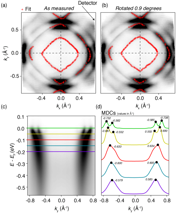
To estimate the azimuthal value we have performed fitting of the -loci of the Fermi surface contours (red markers in Fig.6 a-b) and we have then aligned the horizontal and vertical axis (see the next subsection for fitting details). As one can see, in our configuration, there is negligible misalignment between the states at positive and negative , see Fig. 6 c-d for example. The latter shows, that by extracting momentum-distribution curves (MDCs), coloured horizontal lines in Fig. 6 c) the peak positions are symmetric within the resolutions of the instrument ( 12 meV for energy and Å-1). Therefore, we are in a good condition to safely perform the measurements shown in the main text.
Details of the fitting
The Fermi surfaces -loci shown in Fig. 6 a-b and the positions of the peaks in Fig.5 d have been extracted by fitting the ARPES data. The fitting procedure used is standard and consists of fitting both EDCs and momentum-distribution curves by using Lorentzian curves convoluted by a Gaussian contribution which accounts for the experimental resolutions. Then, as part of the fit results, we extracted the positions of the peaks, which are those reported as red markers in Fig. 6 and the values in Fig. 6 d.
Spin-ARPES data
For the extraction of the values reported, the spin-data shown in the manuscript have been also normalized to include the action of the Sherman function of the instrument. In particular, the data for spin-up and spin-down channels have been normalised to their background, such that this matched in both cases. In the present study, the background normalisation was executed on the high-energy tails of the EDCs far from the region where the actual spin polarization is observed. After normalisation, in order to extract the spin intensity, we used the following relationships:
where is the polarization of the system and is simply the sum of the intensity for EDCs with spin-up and spin-down after normalisation to the background. For the polarisation , the Sherman function from the instrument was included (i.e. =0.3 [2] and calibrated from measurements on gold single crystal). This is described by:
This procedure was done for all light polarizations. Additionally, we also characterized the spin channels by using different polarization vector directions, as shown in Fig.7.
Dichroism and spin-dichroism amplitudes
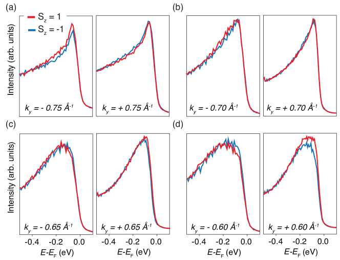
A way to visualise the breaking of the time-reversal symmetry is to analyse the dichroic signal already shown in Fig. 2c of the main text but resolved in the two different spin channels, i.e. up and down, which gives rise to very different amplitude values when measured at (expected for time-reversal symmetry breaking but not expected otherwise). We show this here at a selected momentum values. The amplitude values have been extracted from the data shown in a-b and in Fig. 7, after including the Sherman function normalization.
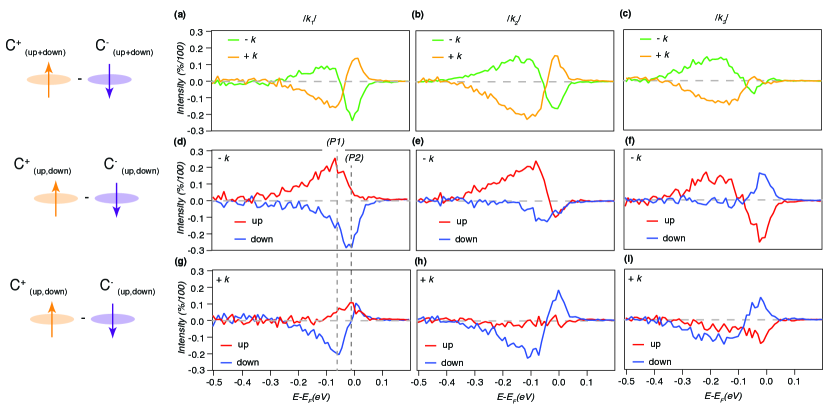
To better understand the claim in the main text, we here show in Fig.8 the relative amplitudes of the dichroic versus spin-dichroic signal. First of all, let us focus on the spin-integrated dichroism shown in Fig.8a. Here, the orange and green curves represent positive and negative values, respectively and their behaviour is overall symmetric with respect to zero. However, a small asymmetry can still be noticed, estimated as large as 10, a value which is very close to previously reported ones [8] ( 8). As we will clarify from a theoretical point of view, a small degree of asymmetry in the spin-integrated dichroism can be still expected, however, the amplitudes of the dichroism selected in their spin channels are supposed to be quite larger. To demonstrate this difference, we have shown how the dichroism curves, resolved in their spin channels (up-red and down-blue), appear at negative (Fig.8d-f) and at positive (Fig.8g-i). By also considering their residuals, we can compare them to the amplitude of the spin-integrated signal. We reported this comparison in Fig.9: The spin-down channel shows an amplitude as high as 30, the spin-up as high as 20. These values are three times and two times bigger, respectively, than the residual extracted for the spin-integrated signal. Such a large difference corroborates the validity of our methodology and the claims of our work. Note that by summing the positive and negative momentum is also counteracting possible effects due to small sample misalignment.
Data and temperature
For completeness, we have also performed and on the sample after cleaving it also at high temperature (HT, 70 K), which is above the magnetic transition of Sr2RuO4. We report the results in Fig.10. In particular, in Fig.10 a-c, the upper panels with blue lines show the difference between and - normalized by their sum - at three values of and at low temperature (LT), while the lower line is the same for the data collected at 70 K. If in the LT configuration we do observe a varying finite signal, at HT we did not see such a variation. It is important to mention that even with our resolution, we do not see any finite signal, there might be still some differences which could be observed above the magnetic transition, because it is likely that not all magnetic excitations are turned off immediately, however, a reduction should be still observed. In addition, the HT data are more noisy: even if we cleaved the samples at HT, and as the ARPES shown in Fig.10 d-e confirms their presence, they are much weaker than in LT and broadened thermally. Such a thermal broadening is not surprising to see in ARPES. Nevertheless, even if with reduced intensity, the surface states are still well visible.
Calibrating the V-LEED
Within the uncertainty of the instrument (1∘ integration region), the V-LEED has been calibrated by acquiring spin EDCs at various angles, both positive and negative values, for the sample. This is done for both spin species and with the used light polarizations. In the present case, for consistency, we did this with circularly polarized light (both left and right-handed). After, by summing up both circular polarizations and both spin species, we can reconstruct as in Fig. 11 the ARPES spectra. This procedure was done by using only the spin-detector to access directly the states probed and be sure that when selecting the angular values on the deflectors we probe effectively the selected state.
Discussion about uncertainties and additional calibration
For evaluating the uncertainty, we used a controlled and known sample with no asymmetries in the dichroic signal, as in our previous work (see Ref. [8]). We used a kagome lattice because at the point there is a well-defined energy gap opened due to the action of spin-orbit coupling. In addition, in this point, the bands are spin-degenerate. Plus, the system is non-magnetic. This allowed us to check the asymmetry not only in the circular dichroism signal, but also in the spin-resolved circular dichroism. We estimated the uncertainty to be approximately 10 on the residual of the dichroism. Note that this is also consistent with what is obtained by standard ARPES in our setup: at the centre of the Brillouin zone, the difference between circular right and circular left polarized spectra (each spectrum was normalized by its own maximum intensity beforehand) is indeed 10.
Supplementary Information
I Model and broken symmetry phases with chiral currents
We consider a two-dimensional system whose electronic states at the Fermi level are described by -orbitals belonging to the manifold (,,) and can accommodate electronic phases which are marked by non-trivial loop currents.
The model Hamiltonian for the surface of the Sr2RuO4 is compatible with the point group symmetry. For the manifold of the orbitals we introduce the components of the local orbital angular momentum. For the spin space, hereafter, we employ the Pauli matrices . Assuming that the basis of the local creation operator of electrons for the -orbitals for a given spin orientation is , we have that the components of the orbital angular momentum are given by:
with fulfilling the usual angular momentum algebra.
Then, in the complete spin-orbital basis, given by , the Hamiltonian can be generally expressed as
| (2) |
with given by
We recall that is the projector on the orbital state with a given distribution that is perpendicular to the direction (e.g. for the projection is on the orbital configuration). Here, is the chemical potential. The term proportional to corresponds to the symmetry allowed hybridization processes of the orbitals along the and orientations. The choice of the following electronic parameters reproduces with good accuracy the experimental profile of the Sr2RuO4 Fermi lines at the surface as measured by ARPES (as in this paper and in Ref. 11, see e.g. Fig. 2):
with , , , , , , , , in units of eV [11]. We assume a weak amplitude for the inversion symmetry breaking term eV, since the induced splitting is below the experimental resolution. The term proportional to represents the orbital Rashba interaction [12, 13, 14, 15] and couples the atomic angular momentum with the crystal wave-vector due to the breaking of inversion symmetry at the surface.
Then, in order to take into account the breaking of time-reversal and mirror symmetry, we consider the spin-orbital chiral current phase along the direction, as given the following term in the Hamiltonian:
| (3) |
Here, we take a representative vector with amplitude eV, with generic coefficients, so that it does not point in any high-symmetry direction in the lattice. The outcome of the orbital and spin-orbital quadrupole moments within the Brillouin zone is not qualitatively affected by the choice of the coefficients. This current term can arise by a mean-field decoupling of the Coulomb interaction for nearest-neighbor Ru centers (see Sect. IV). In Fig. 12 we report the orbital and spin-orbital textures for all the bands assuming different types of broken symmetry chiral phases marked by orbital and spin-orbital quadrupole currents.
In order to capture the different behavior of the orbital and spin-orbital moments in the presence of chiral currents one can consider the equation of motion associated with the expectation values of the spin and orbital moments for a given eigenstate at momentum . In general, the time dependent evolution of the spin and orbital angular momentum is provided by the equation of motion with and being the corresponding torques. For a given eigenstate of the band at momentum , one can write a torque equation for the amplitudes of the spin and orbital moments. The equation of motion reads as with and . Now, since we deal with equilibrium configurations in time-independent conditions the amplitudes of the spin and orbital moments have to fulfill the relations with . These relations in turn set out the amplitude of the spin and orbital moments.
For convenience and clarity, we introduce a Cartesian reference and, without loss of generality, we assume that the chiral current in the broken symmetry phase flows parallel to the -direction. The spin-orbital current in Eq. (3) can be then generally expressed as
| (4) | |||||
Furthermore, it is also convenient to write the Hamiltonian in the following compact form:
| (5) |
with containing the kinetic and the orbital Rashba coupling terms and . We notice that preserves the vertical mirrors ( and ) and the time-reversal symmetries. Then, we point out that among the components of , the term related to is the source of chiral symmetry breaking, as all the mirror symmetries are broken. This is because the components of and are pseudovectors and are perpendicular to the current flow direction. Instead, the other components, related to and , preserve the vertical mirror symmetry.
Let us now consider the spin and orbital amplitudes of the torque by taking for instance the corresponding orientations along the -direction. For this configuration, the commutators of the Hamiltonian with the component of spin and orbital angular momentum yield
| (6) | |||||
| (7) | |||||
| (8) |
where , , and with . On the basis of these relations, the equilibrium condition for the spin torque yields:
| (9) |
with
| (10) | |||||
| (11) |
We notice that in the equation for the torque arising from the component of the spin-orbital current (i.e. ) breaks the mirror symmetry. Instead, the terms related to are mirror-symmetric. We also observe that in the absence of the spin-orbital current the spin torque due to the spin-orbit coupling is identically zero. This implies that the spin and orbital moments must be collinear at any . On the other hand, the presence of the chiral spin-orbital currents leads to a deviation from the collinearity between and .
Let us now consider the analogous equations for the orbital moment. For the commutators with we have:
with and , and . Here, the coefficient is related to the orbital Rashba coupling. Hence, the equation for the orbital moment torque becomes:
| (12) |
with
| (13) | |||||
| (14) | |||||
| (15) | |||||
| (16) |
Now, we observe that and . This relation is a hallmark of the phase with spin-orbital quadrupole currents. Taking into account these relations and the Eq. (9) for the spin torque, one can replace and in the Eq. (12) with the combination of . Hence, one can deduce an equation for the orbital torque that contains only terms that are mirror symmetry compatible. This implies that the expectation value of the orbital moment has a definite parity as for mirror-symmetric systems.
Let us now consider the case of the orbital quadrupole current:
| (17) | |||||
As for the case of the spin-orbital quadrupole current, the term related to break both the horizontal () and vertical ( and ) mirror symmetries, while for the other current components, we have that and preserve . For this configuration one can deduce that the spin torque is not affected (i.e. commutes with ) and that the orbital part includes all the torques due to the current components. Then, the resulting orbital moment has to explicitly manifest a breaking of the mirror perpendicular to the current flow as demonstrated in Fig. 12.
I.1 Surface reconstruction
To take into account the surface reconstruction due to the staggered octahedral rotation we double the unit cell, in order to include both sublattices of the square lattice within the unit cell. Then, the term related to the octahedral rotation can be included in the Hamiltonian as a staggered potential for the -states at the Ru site of the form:
| (18) |
where is a sublattice pseudo-spin operator given by the corresponding Pauli matrix and is a characteristic energy scale of the rotation pattern. This term leads to a staggered splitting of the orbitals at the Ru site that arises due to the local vertical mirrors symmetry breaking resulting from the rotated octahedra. Here, for the computation of the electronic structure, we use a representative value for meV. Variation of the strength of does not alter the qualitative outcome of the analysis. We also introduce a staggered spin-orbital current component as given by the following contribution:
| (19) |
Hence, regarding the chiral current broken symmetry phase, we assume an amplitude modulation of the spin-orbital current along the [110] direction so that it is given by when connecting Ru sites in octahedra that are clockwise rotated and for anticlockwise rotated octahedra.
We have thus considered the possibility of having an amplitude modulation of the spin-orbital quadrupolar currents that follows the surface reconstruction due to the rotation of the RuO6 octahedra.
Then, it is expected that the ground state hosts chiral spin-orbital quadrupole currents which are not spatially homogeneous, being affected by the structural change of the octahedra, that result into different current amplitudes when linking ruthenium sites with inequivalent octahedral rotation.
We have analyzed this configuration as a function of the current amplitude unbalance associated with the two sublattices.
For such a current pattern we find that the band resolved dichroic asymmetry in the reconstructed electronic states (Fig. 13 a) is not exactly zero (Fig. 13 b) as found for the uniform current configuration. In order to get an overall estimate of the difference between the orbital and spin-projected orbital moments as a function of the current sublattice unbalance, we have followed their integrated values (i.e. summing up all the band contributions and integrating along the line). The outcome is reported in Fig. 13 b where one can clearly see that a non-vanishing orbital moment is induced by the spatially modulated chiral currents. Nevertheless, the asymmetry for the orbital moment turns out to be significantly smaller than that related to the spin projected one. For instance, for a spatial modulated configuration of the spin-orbital current with a sublattice unbalance of around 3 we find that the integrated value of the spin-projected orbital moment is about five times larger than that of the orbital moment.
The point here is that the spatially homogeneous chiral spin-orbital current would lead to exact zero asymmetries in the dichroic amplitude due to the balance among the torques arising from the chiral current and that one arising from the spin-orbit coupling. Now, since the spin-orbit coupling at the Ru site is homogeneous, a spatial dependent amplitude of the chiral spin-orbital current cannot be compensated and a non-vanishing amplitude of the dichroic signals can occur. Due to the surface reconstruction of the electronic states in the Sr2RuO4 one might argue that small deviations of the dichroic signals from zero can be consistent with the theoretical prediction when considering the orthorhombic configuration due to the staggered octahedral rotations around the -axis. The main finding is that
one can also account for an amplitude asymmetry of the dichroic signal keeping however a significantly larger spin-dichroic asymmetry as compared to the dichroic one.
Finally, we have verified that for a uniform configuration of the spin-orbital quadrupole currents the asymmetry of the orbital moment at and is identically zero irrespective of the surface reconstruction (Fig. 14).
I.2 C4 rotational invariant spin-orbital chiral phases
We have considered states with spin-orbital chiral loop currents that preserve the C4 rotational symmetry (see Fig. 15). These configurations lead to a symmetric dichroic amplitude and an asymmetric spin-dichroic value as related to the orbital moment and spin projected orbital orbital moment for all bands evaluated along the direction. In particular, due to the symmetries the orbital moment can be vanishing. This implies that for this type of configurations we also expect a large difference between the asymmetry in the dichroic and spin-dichroic signals.
I.3 Canted antiferromagnetic order
We consider the case of a magnetic order with a canted antiferromagnetic configuration. The broken symmetry state is introduced by an effective magnetic term in the spin channel with uniform/staggered magnetization:
| (20) |
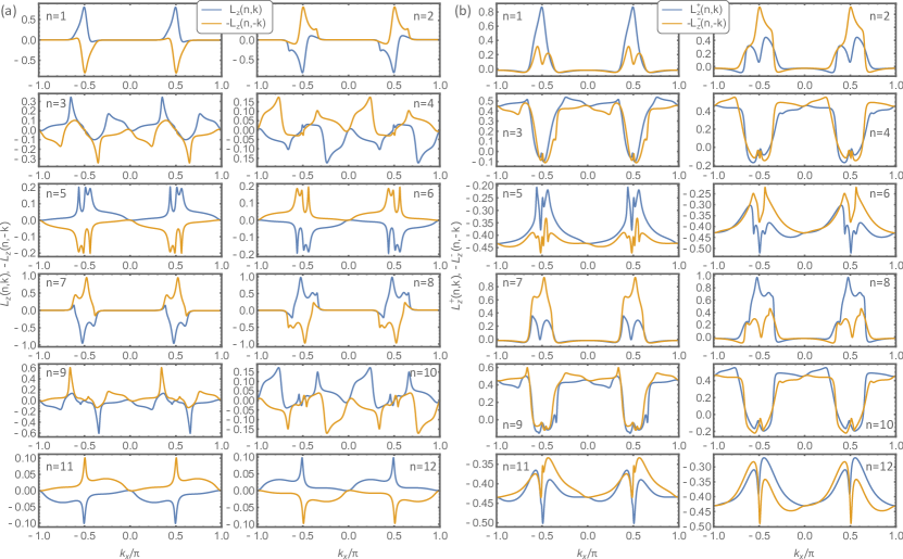
with and being the uniform and staggered magnetization components. We have computed, for a representative antiferromagnetic configuration with canted moments, the orbital and spin-resolved orbital moment for all the bands crossing the Fermi level (Fig. 16). As one case see from the inspection of the results in Fig. 16 the orbital and spin-projected orbital moments exhibit a sizable asymmetry when comparing the amplitudes at and . This is a general feature of all the magnetic phases with similar symmetry content with respect to mirror and time reversal symmetry and based on a long-range spatial order of Ru spin moments.
II Spin resolved circularly polarized ARPES: matrix elements and orbital angular momentum
We report here the main steps to deduce the expressions for the dichroic and spin-dichroic ARPES transition amplitudes. To this aim, we follow the derivation reported in Ref. [13] and adapt it to the spin-dichroic case too. The starting point is to consider that the circular dichroic signals probed by ARPES can be expressed through the normalized amplitude as
| (21) |
The sum over the final state spin indicates the spin-integrated nature of the detection approach. Thus, one can also introduce the spin-resolved dichroic amplitude as given by
| (22) |
here for convenience we assume that the spin configuration is along the -axis and are labeled by to indicate the spin states, respectively. Similar expressions can be derived for the all the other spin orientations.
To calculate the amplitude of the dichroic and spin-dichroic signal one has to evaluate the transition probability for an optical excitation between the initial and final states.
The interaction with the photon is given by . The vector potentials are for right circularly polarized photons, and for left circularly polarized photons. Hence, the vector sets out the incident photon direction.
For convenience and clarity, we report the main steps and expressions of the derivation to show the link of the ARPES intensity with the orbital and spin-projected angular momentum.
Let us consider as initial state the Bloch configuration with momentum that is given by , where is the Wannier configuration centered at the site associated with the orbitals labeled by and spin .
A plane-wave state is assumed for the final state [16, 17] with being the Fermi wave vector.
We recall that the expected value of the orbital angular momentum evaluated on the state is given by
, with and the spin projected orbital components are expressed as , with singling out the spin up and down configuration with respect to the -direction, respectively.
Following the derivation in Ref. [13], one can show that the spin resolved transition probability can be generally expressed as
| (23) |
with
| (24) |
where the gradients are respect to the Fermi wave vector , and is the Fourier transform of the part of the Wannier function that depends only on the radial distance related to the atomic center at . The denominator of is always positive and has a minor role in the dependence of the matrix elements from the orbital angular momentum. The key quantity for our purposes is given by the factor . One can show [13] that the term can be expressed as
| (25) | |||||
| (26) |
with the vector having the following components with . We notice that while the structure of the orbital angular momentum is similar to that of -orbitals because we are using an effective manifold for the sector, the second order differential operator takes into account the different structure of the orbital configurations. In a similar way, one can show that the spin integrated amplitude is given by
| (27) |
with the Levi-Civita tensor.
Then, one can see that the amplitude and thus the dichroic signal is proportional to the projected orbital angular momentum components with respect to the incident photon direction.
Additionally, the spin-dichroic signal is proportional to the spin-projected orbital angular momentum as given with for projecting spin up and down configurations, respectively.
The remaining form factors depend on the Fermi momentum and on the photon energy. Since our study aims to have a qualitative understanding of the anomalies in the transition amplitude probed by Spin CD-ARPES, their contribution does not affect the conclusions of our findings.
In the employed experimental setup the spin orientation is selected in a direction that is perpendicular to the surface (i.e. ) and the incident photon direction is primarily selecting the out-of-plane -component of the orbital angular momentum. Hence, the dichroic and spin-dichroic signal are proportional to and as considered in the manuscript.
III Current driven phase by Coulomb interaction
Let us now present how the electronic current phase arises as a broken symmetry state with a nonvanishing expectation value of the current operator on the Ru-Ru bond due to the Coulomb interaction. Indeed, in order to demonstrate this point one needs to introduce the spin-orbital asymmetric operator
| (28) |
for the bond between two Ru atoms with position identified by the coordinates and . Here, are the annihilation (creation) operators associated with an electronic state with orbital and spin at the atomic site . Then, the spin and orbital dependent terms that build up the density-density inter-site Coulomb interaction for a generic bond can be written in the following form
| (29) | |||||
where the orbital and spin resolved density operators, , are defined as . Hence, by decoupling the quartic term, one can introduce an order parameter associated with the expectation value of and express the interaction as
| (30) | |||||
where the average value indicates the summation over all the electronic states weighted by the Fermi distribution function. Taking into account the spin-orbital order parameters on the bond, by suitable superposition of the operators one can construct a bond current order parameter that is given by the expectation value of the following orbital and spin-orbital quadrupole current operators:
| (31) |
with and .
References
- Fittipaldi et al. [2005] R. Fittipaldi, A. Vecchione, S. Fusanobori, K. Takizawa, H. Yaguchi, J. Hooper, R. Perry, and Y. Maeno, Crystal growth of the new Sr2RuO4–Sr3Ru2O7 eutectic system by a floating-zone method, Journal of Crystal Growth 282, 152 (2005).
- Bigi et al. [2021] C. Bigi, F. Mazzola, J. Fujii, I. Vobornik, G. Panaccione, and G. Rossi, Measuring spin-polarized electronic states of quantum materials: , Phys. Rev. B 103, 245142 (2021).
- Sunko et al. [2019] V. Sunko, E. Abarca Morales, I. Marković, M. E. Barber, D. Milosavljević, F. Mazzola, D. A. Sokolov, N. Kikugawa, C. Cacho, P. Dudin, H. Rosner, C. W. Hicks, P. D. C. King, and A. P. Mackenzie, Direct observation of a uniaxial stress-driven Lifshitz transition in Sr2RuO4, npj Quantum Materials 4, 46 (2019).
- Beaulieu et al. [2020] S. Beaulieu, J. Schusser, S. Dong, M. Schüler, T. Pincelli, M. Dendzik, J. Maklar, A. Neef, H. Ebert, K. Hricovini, M. Wolf, J. Braun, L. Rettig, J. Minár, and R. Ernstorfer, Revealing hidden orbital pseudospin texture with time-reversal dichroism in photoelectron angular distributions, Phys. Rev. Lett. 125, 216404 (2020).
- Scholz et al. [2013] M. R. Scholz, J. Sánchez-Barriga, J. Braun, D. Marchenko, A. Varykhalov, M. Lindroos, Y. J. Wang, H. Lin, A. Bansil, J. Minár, H. Ebert, A. Volykhov, L. V. Yashina, and O. Rader, Reversal of the circular dichroism in angle-resolved photoemission from , Phys. Rev. Lett. 110, 216801 (2013).
- Park et al. [2012] J.-H. Park, C. H. Kim, J.-W. Rhim, and J. H. Han, Orbital Rashba effect and its detection by circular dichroism angle-resolved photoemission spectroscopy, Phys. Rev. B 85, 195401 (2012).
- Cho et al. [2018] S. Cho, J.-H. Park, J. Hong, J. Jung, B. S. Kim, G. Han, W. Kyung, Y. Kim, S.-K. Mo, J. D. Denlinger, J. H. Shim, J. H. Han, C. Kim, and S. R. Park, Experimental observation of hidden Berry curvature in inversion-symmetric bulk , Phys. Rev. Lett. 121, 186401 (2018).
- Di Sante et al. [2023] D. Di Sante, C. Bigi, P. Eck, S. Enzner, A. Consiglio, G. Pokharel, P. Carrara, P. Orgiani, V. Polewczyk, J. Fujii, P. D. C. King, I. Vobornik, G. Rossi, I. Zeljkovic, S. D. Wilson, R. Thomale, G. Sangiovanni, G. Panaccione, and F. Mazzola, Flat band separation and robust spin Berry curvature in bilayer kagome metals, Nature Physics 19, 1135–1142 (2023).
- Damascelli et al. [2000] A. Damascelli, D. H. Lu, K. M. Shen, N. P. Armitage, F. Ronning, D. L. Feng, C. Kim, Z.-X. Shen, T. Kimura, Y. Tokura, Z. Q. Mao, and Y. Maeno, Fermi surface, surface states, and surface reconstruction in , Phys. Rev. Lett. 85, 5194 (2000).
- Tamai et al. [2019] A. Tamai, M. Zingl, E. Rozbicki, E. Cappelli, S. Riccò, A. de la Torre, S. McKeown Walker, F. Y. Bruno, P. D. C. King, W. Meevasana, M. Shi, M. Radović, N. C. Plumb, A. S. Gibbs, A. P. Mackenzie, C. Berthod, H. U. R. Strand, M. Kim, A. Georges, and F. Baumberger, High-resolution photoemission on reveals correlation-enhanced effective spin-orbit coupling and dominantly local self-energies, Phys. Rev. X 9, 021048 (2019).
- Zabolotnyy et al. [2013] V. Zabolotnyy, D. Evtushinsky, A. Kordyuk, T. Kim, E. Carleschi, B. Doyle, R. Fittipaldi, M. Cuoco, A. Vecchione, and S. Borisenko, Renormalized band structure of Sr2RuO4: A quasiparticle tight-binding approach, Journal of Electron Spectroscopy and Related Phenomena 191, 48 (2013).
- Park et al. [2011] S. R. Park, C. H. Kim, J. Yu, J. H. Han, and C. Kim, Orbital-angular-momentum based origin of rashba-type surface band splitting, Phys. Rev. Lett. 107, 156803 (2011).
- Park et al. [2012] J.-H. Park, C. H. Kim, J.-W. Rhim, and J. H. Han, Orbital rashba effect and its detection by circular dichroism angle-resolved photoemission spectroscopy, Phys. Rev. B 85, 195401 (2012).
- Kim et al. [2013] B. Kim, P. Kim, W. Jung, Y. Kim, Y. Koh, W. Kyung, J. Park, M. Matsunami, S.-i. Kimura, J. S. Kim, J. H. Han, and C. Kim, Microscopic mechanism for asymmetric charge distribution in rashba-type surface states and the origin of the energy splitting scale, Phys. Rev. B 88, 205408 (2013).
- Mercaldo et al. [2020] M. T. Mercaldo, P. Solinas, F. Giazotto, and M. Cuoco, Electrically tunable superconductivity through surface orbital polarization, Phys. Rev. Appl. 14, 034041 (2020).
- Damascelli et al. [2003] A. Damascelli, Z. Hussain, and Z.-X. Shen, Angle-resolved photoemission studies of the cuprate superconductors, Rev. Mod. Phys. 75, 473 (2003).
- Moser [2017] S. Moser, An experimentalist’s guide to the matrix element in angle resolved photoemission, Journal of Electron Spectroscopy and Related Phenomena 214, 29 (2017).
Acknowledgements
F.M. greatly acknowledges the SoE action of PNRR, number SOE_0000068. M.C., R.F., M.T.M., and A.V. acknowledge support from the EU’s Horizon 2020 research and innovation program under Grant Agreement No. 964398 (SUPERGATE). M.C. and G.P. acknowledge financial support from PNRR MUR project PE0000023-NQSTI. M.C., R.F., A.G., and A.V. acknowledge partial support by the Italian Ministry of Foreign Affairs and International Cooperation, grant number KR23GR06. W.B. acknowledges support by Narodowe Centrum Nauki (NCN, National Science Centre, Poland) Project No. 2019/34/E/ST3/00404 and partial support by the Foundation for Polish Science through the IRA Programme co-financed by EU within SG OP. This work was performed in the framework of the Nanoscience Foundry and Fine Analysis (NFFA-MUR Italy) facility. J.A.M acknowledges financial support from DanScatt (7129-00011B).