Performance enhancement of electrocatalytic hydrogen evolution through coalescence-induced bubble dynamics
Abstract
The evolution of electrogenerated gas bubbles during water electrolysis can significantly hamper the overall process efficiency. Promoting the departure of electrochemically generated bubbles during (water) electrolysis is therefore beneficial. For a single bubble, a departure from the electrode surface occurs when buoyancy wins over the downward-acting forces (e.g. contact, Marangoni, and electric forces). In this work, the dynamics of a pair of H2 bubbles produced during hydrogen evolution reaction in 0.5 M H2SO4 using dual platinum micro-electrode system is systematically studied by varying the electrode distance and the cathodic potential. By combining high-speed imaging and electrochemical analysis, we demonstrate the importance of bubble-bubble interactions for the departure process. We show that bubble coalescence may lead to substantially earlier bubble departure as compared to buoyancy effects alone, resulting in considerably higher reaction rates at constant potential. However, due to continued mass input and conservation of momentum repeated coalescence events with bubbles close to the electrode may drive departed bubbles back to the surface beyond a critical current, which increases with the electrode spacing. The latter leads to the resumption of bubble growth near the electrode surface, followed by buoyancy-driven departure. While less favourable at small electrode spacing, this configuration proves to be very beneficial at larger separations increasing the mean current up to 2.4 times compared to a single electrode under the conditions explored in this study.
2_ESI \captionsetupfont=sf,small Twente]Physics of Fluids Group, Max Planck Center for Complex Fluid Dynamics and J. M. Burgers Centre for Fluid Dynamics, University of Twente, Enschede, Netherlands Leiden]Leiden Institute of Chemistry, Leiden University, Leiden, Netherlands Twente]Physics of Fluids Group, Max Planck Center for Complex Fluid Dynamics and J. M. Burgers Centre for Fluid Dynamics, University of Twente, Enschede, Netherlands Twente2]Soft Matter, Fluidics and Interfaces, MESA+ Institute for Nanotechnology, J. M. Burgers Centre for Fluid Dynamics, University of Twente, Enschede, Netherlands Leiden]Leiden Institute of Chemistry, Leiden University, Leiden, Netherlands Twente]Physics of Fluids Group, Max Planck Center for Complex Fluid Dynamics and J. M. Burgers Centre for Fluid Dynamics, University of Twente, Enschede, Netherlands \alsoaffiliation[MaxPlanck]Max Planck Institute for Dynamics and Self-Organization, Göttingen, Germany Twente]Physics of Fluids Group, Max Planck Center for Complex Fluid Dynamics and J. M. Burgers Centre for Fluid Dynamics, University of Twente, Enschede, Netherlands
1 Introduction
Water electrolysis is likely to become a central technology in the CO2-neutral energy system of the future. Apart from being a potential energy carrier and fuel, hydrogen gas serves as a feedstock for the chemical (e.g. ammonia production for fertilisers) and steel industries (coal replacement), and refineries (methanol, synthetic fuels) 1, 2, 3. Yet, the process efficiency requires further improvement to compete on the energy market and enable large-scale hydrogen production. In both conventional alkaline and proton exchange membrane water electrolyzers a considerable part of the overpotentials and hence losses can be attributed to the formation of H2 and O2 bubbles, present at the electrodes and in the bulk.4, 5, 6, 7 These bubbles block the electrodes by masking their active surface area, reducing the number of nucleation sites. Additionally, they raise ohmic resistance by blocking the ion-conducting pathways.8, 9, 10 It is therefore vital to maintain a bubble-free electrode area for continuous catalytic activity. Enhanced removal of gas bubbles and deeper insights into their evolution processes will benefit further optimization of the system’s energy efficiency 11.
Various methods have been developed to aid bubble departure, categorized as active (e.g., sonication, centrifugal forces, mechanical convection, pressure modulation, external magnetic fields) and passive approaches.12, 5, 7, 13 Passive methods, preferred for their energy-efficiency, primarily involve surface modifications to alter the wettability14 of the catalytic surface.15 For example, superhydrophilic surfaces facilitate earlier bubble departure due to the reduced contact angle at liquid-solid interfaces.16, 17, 18, 19, 20, 21, 22
The bubble removal process can also benefit from hydrophobic surfaces. One example is the bubble-free electrolysis concept that employs a hydrophobic porous layer adjacent to a porous electrode. This prevents bubble formation within the catalyst, guiding the generated gas by capillary effects through the hydrophobic layer 23, 24, 25, 26. A different concept to enhance gas removal, which was shown to hold promise based on theoretical analysis,27 is the use of hydrophobic islands on the electrode as preferential nucleation sites. Also practically, this has been shown to be feasible using electrodes partially covered with hydrophobic spots made of polytetrafluoroethylene (PTFE)28, 29, 30. This allows to guide the produced gas away from the active areas of the electrode with the potential to lower the bubble-induced overpotentials 28, 29. Brussieux et al. 30 demonstrated that, depending on the size of and distance between islets, parameters of the gas release such as bubble size and location can be controlled, but did not study the effect on electrode performance. More recently, Lake et al. 31 found that densely packed Pt-coated micropost arrays promote consistent release of smaller bubbles through their mutual coalescence. While this enhanced the stability of the current compared to untextured electrodes, it did not lead to performance gains when normalising by the active surface area in this system, due to additional bubbles forming in between the pillars. In this context, coalescence induced removal of bubbles is of particular interest. Coalescence leads to a reduction in surface energy and this difference is in part converted to kinetic energy, causing the bubble to jump off the surface without having to rely on buoyancy. This makes this removal process also highly attractive in microgravity applications.32, 33, 34, 35, 36, 37, 38
However, a detailed understanding of the mechanism and quantification of the extent to which coalescence-induced dynamics can be exploited to improve the performance of gas-evolving electrodes is still lacking. This also applies to parameter optimisation, which in view of complications such as a possible bubble return to the electrode surface,39, 40, 41, 42, 43, 38, 44 is highly nontrivial. We address these open questions in the present work by studying the coalescence-driven dynamics of hydrogen bubbles produced at a dual micro-electrode during water electrolysis. This new setup allows precise control of important parameters such as the bubble size during coalescence, while also providing excellent observability of the dynamics. We demonstrate that coalescence events may lead to both premature bubble departure compared to buoyancy effects alone and the return of departed bubbles to the surface of the electrode, substantially altering the reaction rates. The dual micro-electrode configuration shows, depending on the applied potential and inter-electrode distance, up to a 2.4-fold increase in current compared to a single micro-electrode.
2 Methods
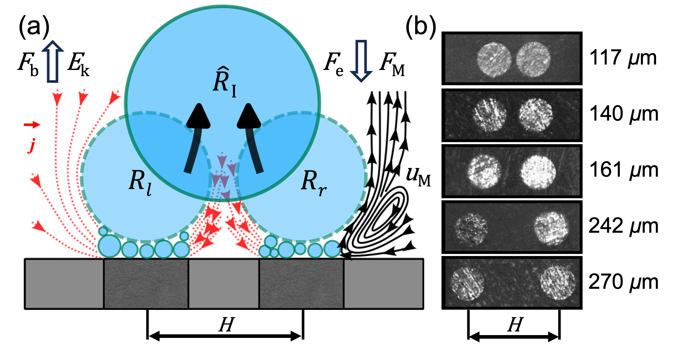
The pairs of H2 bubbles sketched in figure 1a were generated at the surface of a dual platinum micro-electrode during the hydrogen evolution reaction (HER). The experiment was performed in a three-electrode electrochemical cell filled with 0.5 M H2SO4.
The fabrication of dual micro-electrodes followed a previously established method.45 Briefly, two Pt wires (100 m, 99.99%, Goodfellow) were sealed into a soda-lime glass capillary (outer diameter 1.4 mm, inner diameter 1.12 mm, Hilgenberg) by gently softening the capillary in a flame. Five different values for the interelectrode distance H were established and tested, as shown in fig. 1b. The electrode surface underwent electrochemical cleaning (potential cycling between 0.03…1.35 V vs. RHE , repeated 50 times) after being mechanically polished with sandpaper (2000 grit), sonicated and rinsed with ultrapure water. The cell used here closely resembles that used in earlier studies 46, 44, 45. The dual micro-electrode (cathode) is inserted horizontally facing upward in the base of a cuboid glass cuvette (Hellma) with dimensions of 10 10 40 mm3. The system is completed by the reference electrode (Ag/AgCl) and counter electrode ( 0.5 mm Pt wire) both inserted vertically from the top. The electrochemical cell is controlled by a potentiostat (BioLogic, VSP-300, 6 channels) at a constant potential of -0.2 to -2.8 V (vs. RHE). Each of the two electrodes is connected to and controlled by a separate channel of the potentiostat. For each experimental run, the electric current was recorded with a sampling rate of at least 1 kHz over a period of 30 s.
The optically transparent cell allows visualization of the bubble dynamics using a shadowgraphy system. It consists of LED illumination (SCHOTT, KL 2500) with a microscope, connected to a high-speed camera (Photron, FASTCAM NOVA S16), providing a spatial resolution of 996 pix/mm. Image recording was typically performed at 5 kHz, unless otherwise stated. High-speed recording up to 264 kHz was used to resolve individual coalescence events. The bubble radius was extracted by standard image processing routine based on the Canny edge detection method in Matlab R2022b (for further details see Supplemental Material in Bashkatov et al. 47). To measure the velocity fields around H2 bubbles presented in figure 6, monodisperse polystyrene particles (microParticles GmbH) of 5 m were seeded into the electrolyte. These particles are neutrally buoyant with a mass density of 1.05 g/cm³. The resulting series of images, recorded at 1000 frames per second, were processed by the software DaViS 10, which employs a Particle Tracking Velocimetry (PTV) algorithm to track each particle over 25 ms shortly before departure. Due to the limited number of particles close to or at the bubble-electrolyte interface, the resulting tracks of the particles were collected for 60 bubbles. Subsequently, the tracks were converted into a vector field using a binning function that interpolates local tracks on a specified fine grid.
3 Single electrode
To set the baseline, we briefly report the results for the case where only a single electrode is operated, which has been studied previously.48, 49, 50, 46, 51, 52, 47, 38, 44, 53, 54, 55 As an example, figure 2a shows the transient current () and radius () of the bubble for three complete bubble evolution cycles at -1.0 V. Shadowgraphs corresponding to a complete cycle from nucleation 56, 57, 58 to departure are included in figure 2b. This process is highly periodic with a bubble lifetime . The evolution of the bubble has a strong influence on the reaction current, for which the maxima in cathodic current marked by the red circles coincide with the departure of the bubble. This is immediately followed by the nucleation of a new bubble, whose growth in the vicinity of the electrode leads to a considerable reduction in of up to 50% in this case. This continues until the next bubble departure, after which the cycle repeats itself.
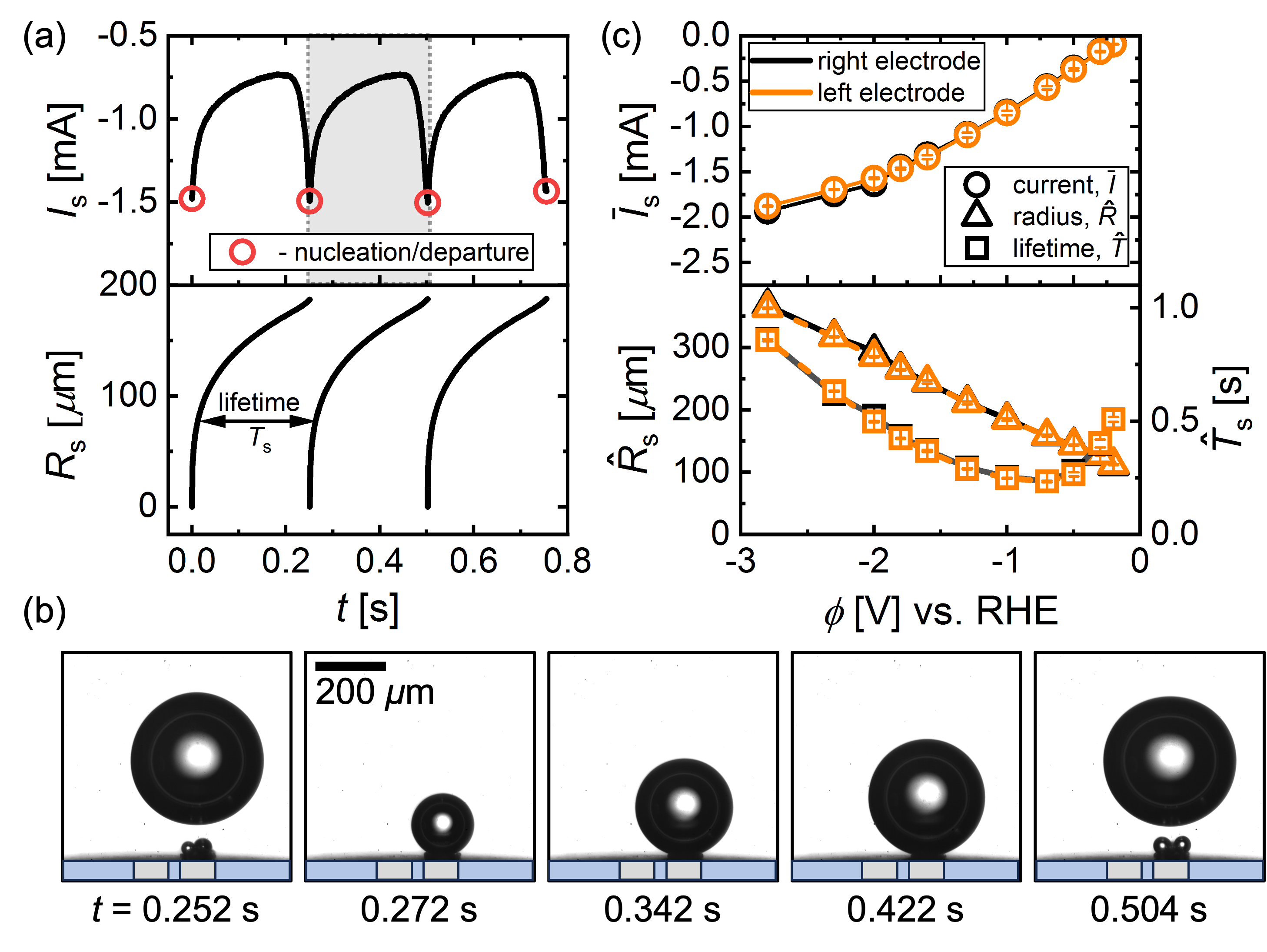
Finally, figure 2c summarizes how the average electric current , where the overline denotes an average over , the departure radius (), and lifetime () varies for different cathodic potentials (). All statistics are averaged over multiple bubble cycles with error bars representing the standard deviation. The figure also confirms that consistent results are obtained from both electrodes.
In this system, bubble formation occurs already at low overpotentials. Micron-sized bubbles form on the electrode surface and continuously coalesce to form a single larger bubble. This larger bubble is typically not in direct contact with the electrode surface, but rather resides on the layer of microbubbles44. It continues to grow via the intensive coalescence with these microbubbles and via gas diffusion59. In this case, departure of the bubble occurs once the retaining forces due to the electric field44, thermal60, 61, 62, 63 and solutal45 Marangoni effects are overcome by buoyancy (see figure 1a). The thermal Marangoni effect is related to the Joule heating caused by the locally high current density () at the bubble foot as indicated in figure 1a. The effect therefore scales (via Ohm’s law) with and prevails at high overpotentials. The solutal effect due to the depletion of the electrolyte at the electrode is expected to depend linearly on and therefore dominates at lower overpotentials ( V in the present case)45. The electric force is directly proportional to and therefore all retaining forces diminish as the overpotential is reduced, which explains the decreasing trend of the departure radius as is made less negative. Since the bubble captures almost all the produced gas46, 45, the departure period follows from the time it takes to produce the gas contained in the bubble volume and is therefore proportional to .
4 Dual electrode
4.1 Modes of bubbles evolution
From now on, both electrodes are operated simultaneously, independently of each other, and at the same potential. Initially, we will only consider the pair with a separation of m. The measured currents for this configuration are plotted in figure 3a for different potentials. Time traces of the current for both electrodes (’left’ and ’right’) are included and for reference we also show the current signal measured when only a single electrode is operated at the same potential (grey line). Focusing initially on the lowest overpotential, V, the current oscillations remain periodic during dual operation; however, both the period and amplitude are notably diminished. The reason for this can be understood from the corresponding shadowgraphs presented in figure 3b, which illustrate the bubble dynamics over one period (shown by black box in fig. 3a).
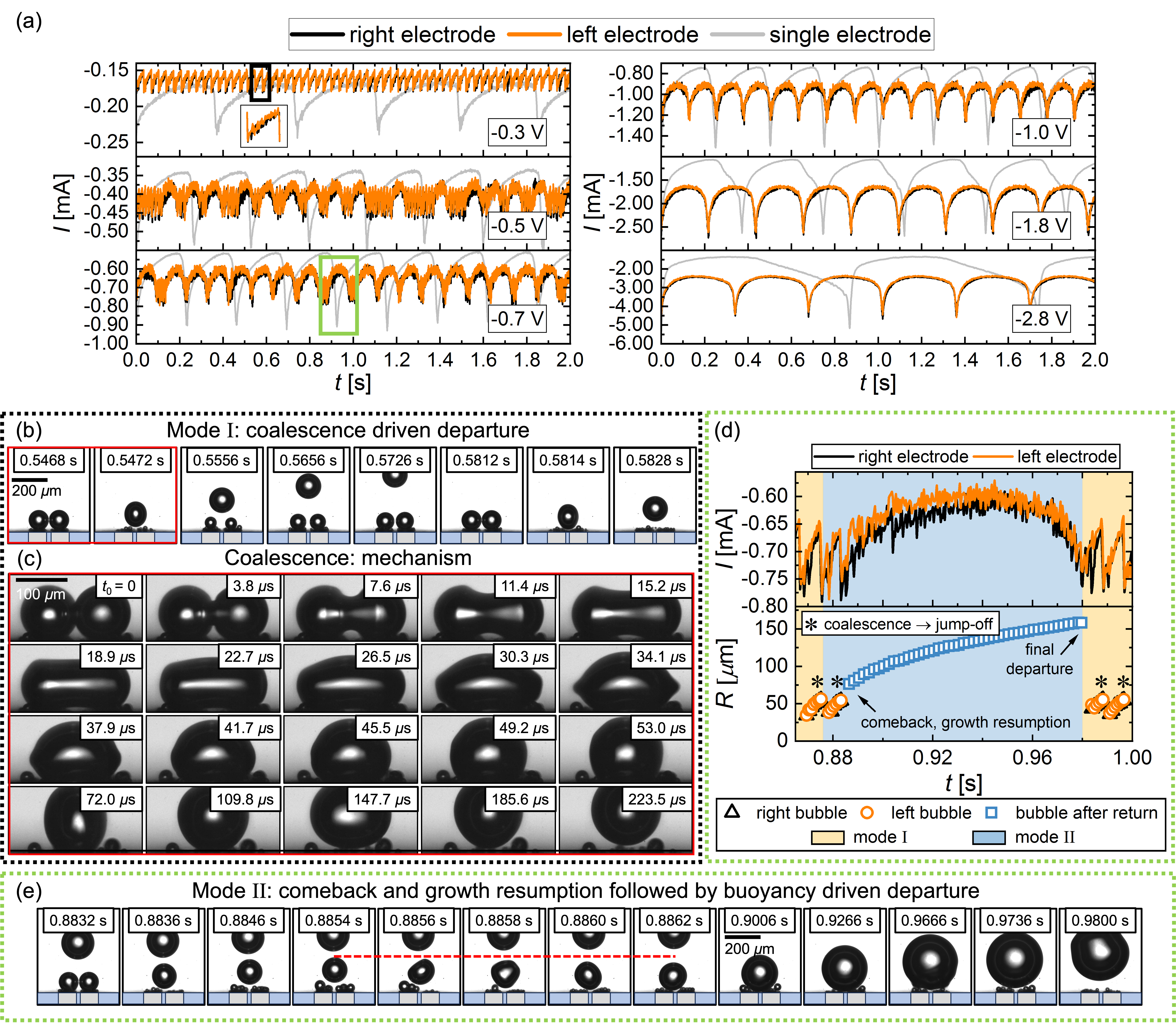
Similar to what is observed for a single electrode, a larger bubble forms and grows initially at each of the two electrodes, leading to a gradual reduction in the current. This process continues until the two bubbles touch and coalesce, which is followed by the departure of the merged bubble along with a spike in the current (see inset at -0.3 V in fig. 3a). Figure 3c details this coalescence process, which happens on the order of micro-seconds, and the emerging deformations of the bubble shape. The coalescence induced jump-off is powered by the released surface energy64, 65, 38. While the majority of this energy is dissipated through the capillary waves seen in figure 3c 66, 37, the fraction that is transformed into kinetic energy (less than 1%, for details see Supporting Information) can cause bubble departure at much smaller radii than in the buoyancy-driven scenario, for the newly formed bubble. Together with the fact that each of the coalescing bubbles only contributes half the volume, this explains the significantly enhanced departure frequency.
At higher overpotential at V, events with a much longer period length start appearing intermittently in the current traces. These events become more frequent and dominate the signal at V, before almost fully superseding the high-frequency coalescence pattern at V. In order to elucidate the underlying bubble dynamics, we provide an enlarged view of a segment of the current signal at V (green box) in figure 3d along with the size evolution of the bubbles. The first bubble departure included in figure 3d proceeds analogously to the one shown in figure 3b, and the bubble continues to rise away from the electrode after the coalescence induced take-off. We will refer to this as ’mode I’ from now on. However, as the corresponding shadowgraphs in figure 3e show, even though the bubble also jumps off after the second coalescence event, it is eventually brought back to the surface through repeated coalescence with newly formed bubbles at both electrodes (see period between s and s). Following this return, the bubble rests between the two electrodes just above the surface. There, it continues to grow until a buoyancy driven departure (at m vs. m), which explains an order of magnitude longer lifetime ( = 104.4 ms vs. = 8.4 ms) of the bubble in this instance. We will denote this as ’comeback mode’ or ’mode II’.
It is evident from figure 3a that the dynamics induced by coalescence have a strong impact not only on the current fluctuations, but also on the mean current at a specific potential. To analyse this, we compare period averaged currents for the two modes ( and , taken to be the sum of the currents at both electrodes) to in figure 4.
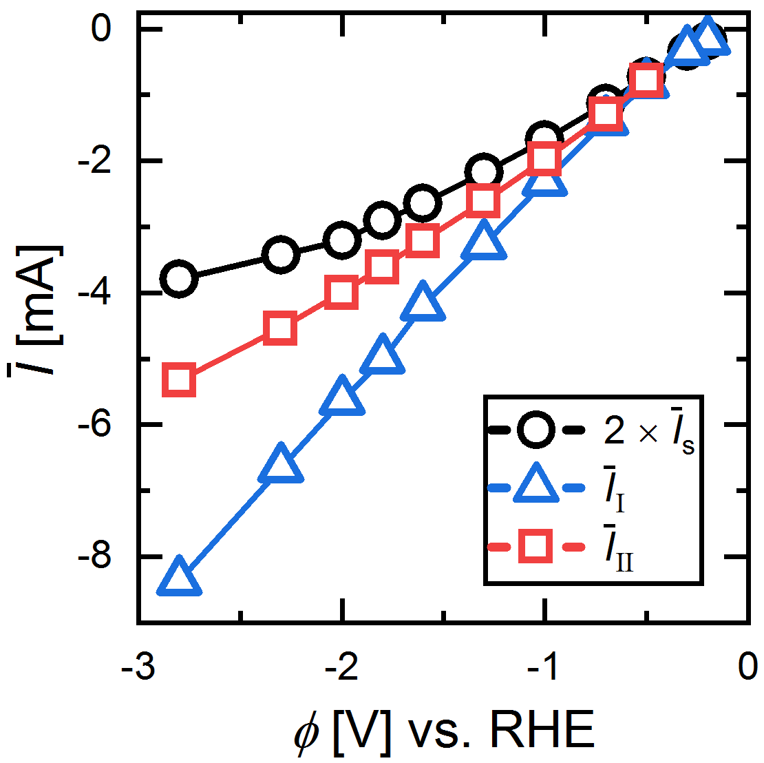
Note that it is possible to determine even at high potentials where mode II prevails by considering only the time until the first coalescence, leading to temporary departure of the bubble (see figure 3d). Despite the much faster gas removal, the current at low overpotentials ( V) remains the same or even slightly decreases in dual operation compared to the single electrode case. This can be attributed to the additional shielding by the second bubble in the vicinity of the electrode and the diffusive competition between the two reaction sites, both of which lower performance. However, the benefits of the accelerated gas removal increasingly outweigh these effects as the overpotential is increased. This is particularly true for mode I, where the current is more than double than that of the single electrode at the same potential for the most negative values of investigated. While this clearly demonstrates the potential for performance enhancement through coalescence-induced gas removal, the effective performance enhancement is reduced to less than 50% for the current electrode spacing due to the prevalence of bubble return (mode II) at higher overpotentials. The currents in mode II are consistently lower compared to mode I because the electrode separation is so small, that the returning bubble still blocks a large part of both electrodes (see figure 3e), even though it is located half-way between them.
4.2 Phase diagram
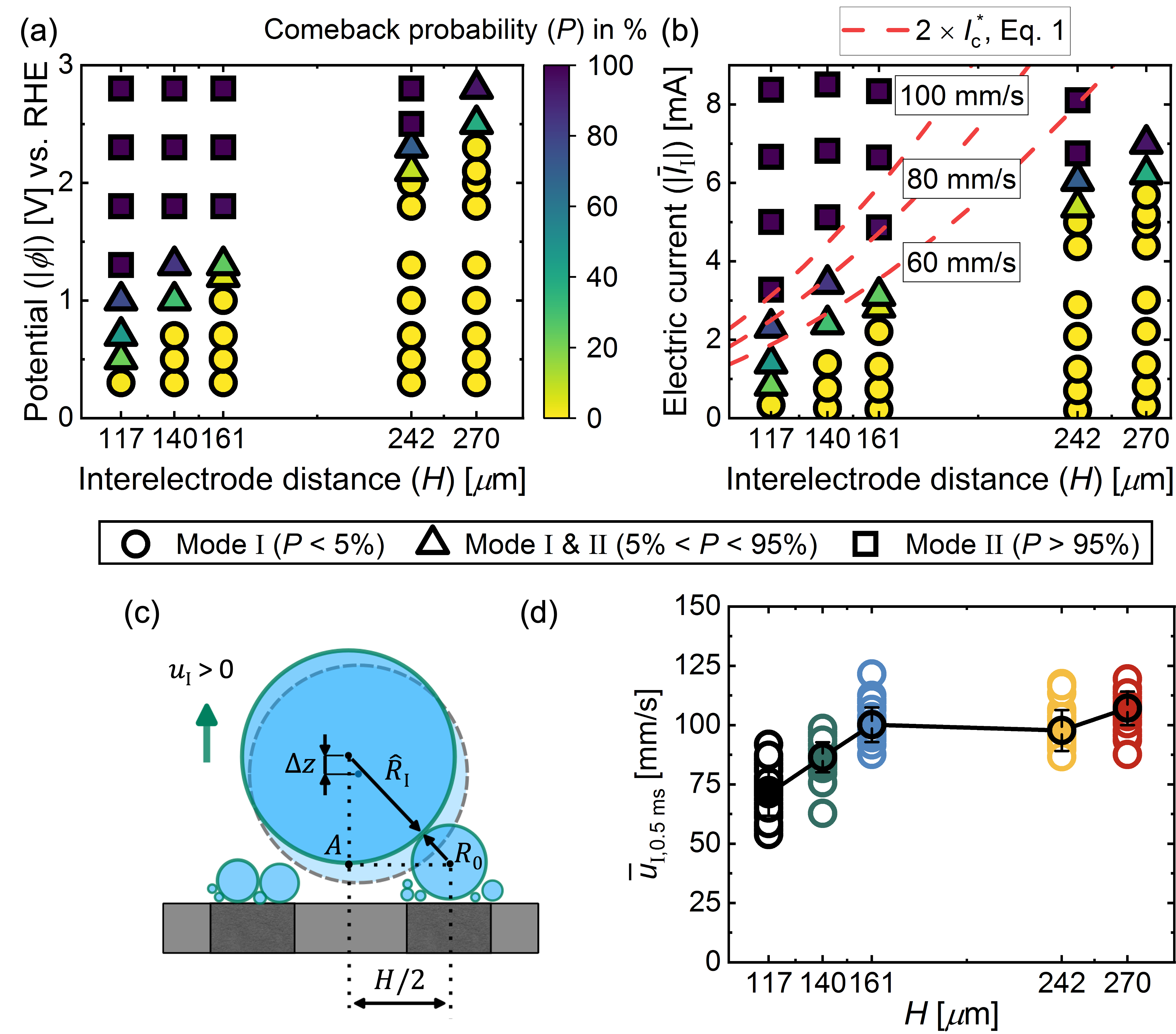
To better understand under what conditions under which the return of the bubble after jump-off happens, figure 5 documents the probability (P) of return for different interelectrode distances () and as a function of (figure 5a) and (figure 5b). As is increased, the transition from mode I (, circles), to a mixed regime (, triangles) and finally to mode II (, squares) occurs at increasingly larger values of . In fact, the dependence on is quite strong: for a fixed potential of -1.3 V, changes from about 100% at m to almost 0 when the distance is increased to m. The sketch in figure 5c illustrates the relevant mechanism for the bubble return. A newly formed bubble (with radius ) on one of the electrodes catches up and coalesces with the departed bubble with radius . Due to momentum conservation, the resulting bubble is then located at the joint center of mass of the two coalescing bubbles, which implies a downward shift by compared to the location of the bubble with radius . Repeated coalescence events from both sides then bring the bubble back to the surface as seen in figure 3e. The transition between mode I and mode II is therefore governed by a competition between the departure or ‘jump’ velocity of a bubble after coalescence and the growth rate of bubbles at the electrode. A larger magnitude of electric current, increasing approximately linearly with (see figure 6), enables faster formation of new bubbles which then increases the likelihood of their interaction with the previously departed bubble. Upon increasing the bubble-successor needs to grow to a larger size, hence for a longer time before interacting with the already departed bubble, allowing the latter to move farther away. This will dramatically increase the current required for comeback mode. We can capture this in a simple model based on the geometry sketched in figure 5c to predict the minimum current for bubble return. Our analysis considers the situation where the new bubble with radius has grown large enough to get in contact with the departing bubble. The time it takes for the bubble to grow to the radius is , where is a prefactor containing the Faraday constant , the pressure inside the bubble , the gas constant and the temperature (see Supporting Information for details). During this time interval, the departing bubble travels the distance , with denoting the effective jump velocity. Based on the geometry of the triangle spanned by the centers of the two bubbles and the point A in figure 5c, the critical current for the mode transition as a function of is given by
| (1) |
For any , a value of can be determined for which reaches a minimum value, . To obtain the value of the current in this critical configuration, an estimate of the jump velocity is required. To obtain this, we tracked bubbles departing after coalescence and then averaged their vertical velocity over the first 0.5 ms to obtain . Note that varies widely depending on the position of both bubbles before coalescence (see Supporting Information for details). The results for this quantity are shown in figure 5d as a function of . From these data, typical values for are found to be in the range from 60 mm/s to 110 mm/s with a slight tendency towards higher velocities as the bubble size increases at larger electrode separations . In figure 5b, we have included results for as a function of and for different values of . It can be seen that the model very well captures the increase of the critical current as the electrode separation increases. The best agreement between the model and the data is for mm/s, which is close to, although slightly lower, than the measured jump velocities in figure 5d. Among potentially other factors, a reason for this slight difference is the fact that the new bubble with radius is also formed by coalescence and therefore also jumps off the electrode. Additionally, we do not account for shape oscillations of the larger bubbles, which become more prevalent at larger .
4.3 Performance vs. Inter-electrode distance, H
To understand how the current varies at different electrode separations, it is useful to first consider how the departure size of the bubbles changes for different . In mode I, the departure is coalescence-driven so that is independent of and varies only with the interelectrode distance . Due to lateral oscillations of the bubble position on the electrode and possibly a slight inclination of the electrode surfaces, the results for shown in figure 6a are about 10% lower than , i.e. the value for the coalescence of two bubbles each with a radius of . This small difference was taken into account when evaluating in equation 1.
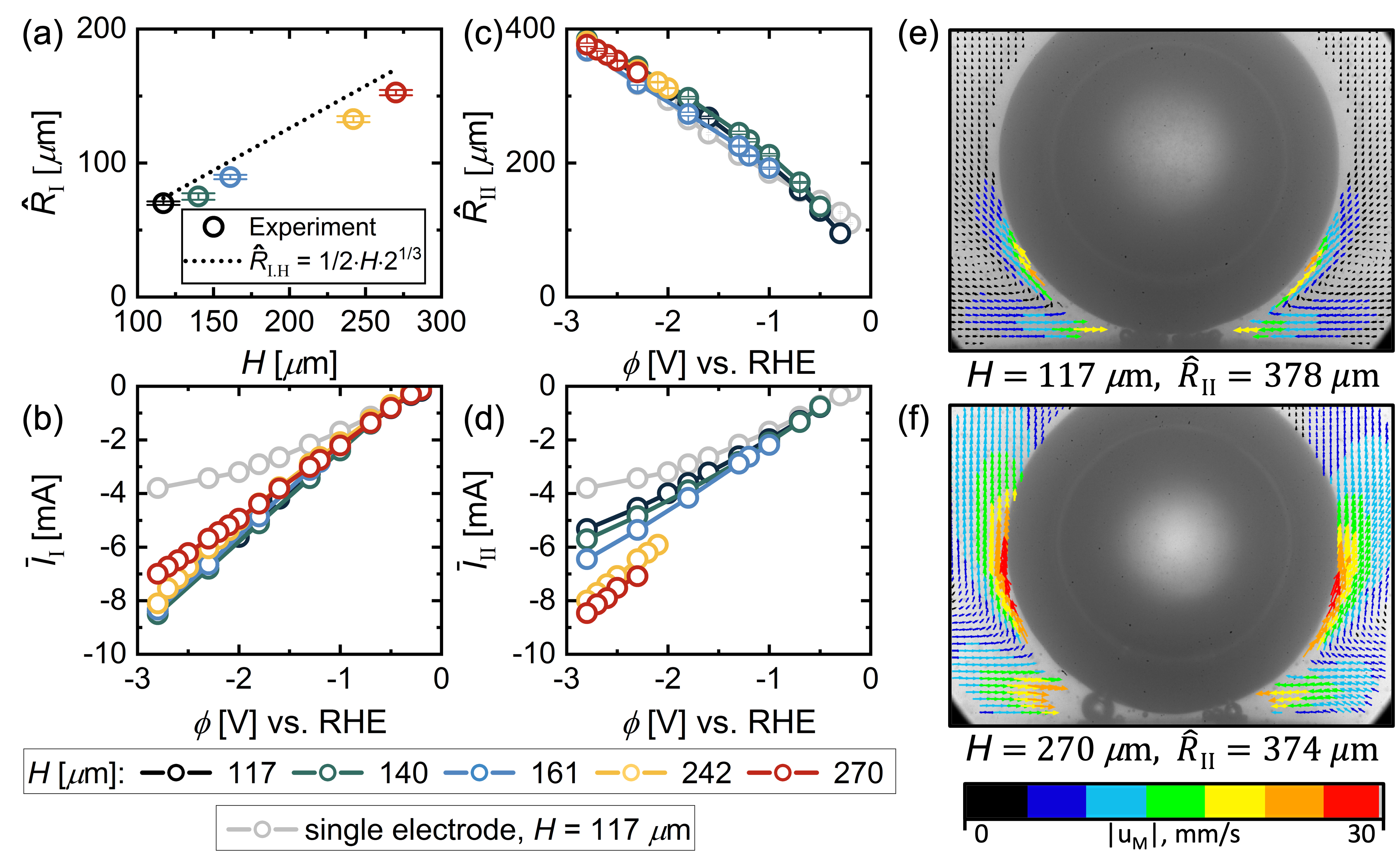
Compared to the single electrode, the current in mode I shown in figure 6b is most enhanced at high overpotential and small , because in this case the reduction in bubble departure size is maximal. There is only moderate decrease of for larger primarily due to the relatively small range in and, consequently, in , which is minor compared to variations observed in at different potentials. At low overpotentials, for the larger electrode separations studied and there is no increase of the current compared to , just as was observed at m in figure 4.
In mode II, the departure radius strongly depends on the potential but at most weakly on , as shown in figure 6c. Remarkably, is approximately the same as for the single electrode case at the same potential (see grey symbols representing ). An investigation of the force balance 67, 68, 69 leading to these trends in are beyond the scope of this study. Nevertheless, we present clear evidence of Marangoni convection (see figures 6(e,f)), consistent with the presence of thermocapillary effects in the same potential range on single electrodes.63, 51 Based on the flow direction, a resulting downward Marangoni force on the bubble is expected (see figure 1a). The convective motion is much more pronounced at m (figure 6f) compared to the narrower spacing of m in figure 6e, which is in line with the difference in current between the two cases ( mA vs. 8.46 mA, respectively). Interestingly, this does not result in a noticeable difference in for the different interelectrode distances, which is presumably due to differences in the geometry dependent electric force.69 We confirmed that the continued coalescence with small bubble does not exert a significant apparent force on the bubble (see Supporting Information for details).
In contrast to mode I, the current in mode II shown in figure 6d shows a clear dependence on the electrode separation and increases strongly for larger . This is because the bubble is now centered in between the two electrodes. Therefore the electrodes become more exposed as the distance between them increases, even if the bubble size remains the same. The continuous removal of the smaller bubbles on the electrode by coalescence with the larger one proves to be very beneficial and leads to maximum currents of more than twice , equalling the largest currents observed in mode I.
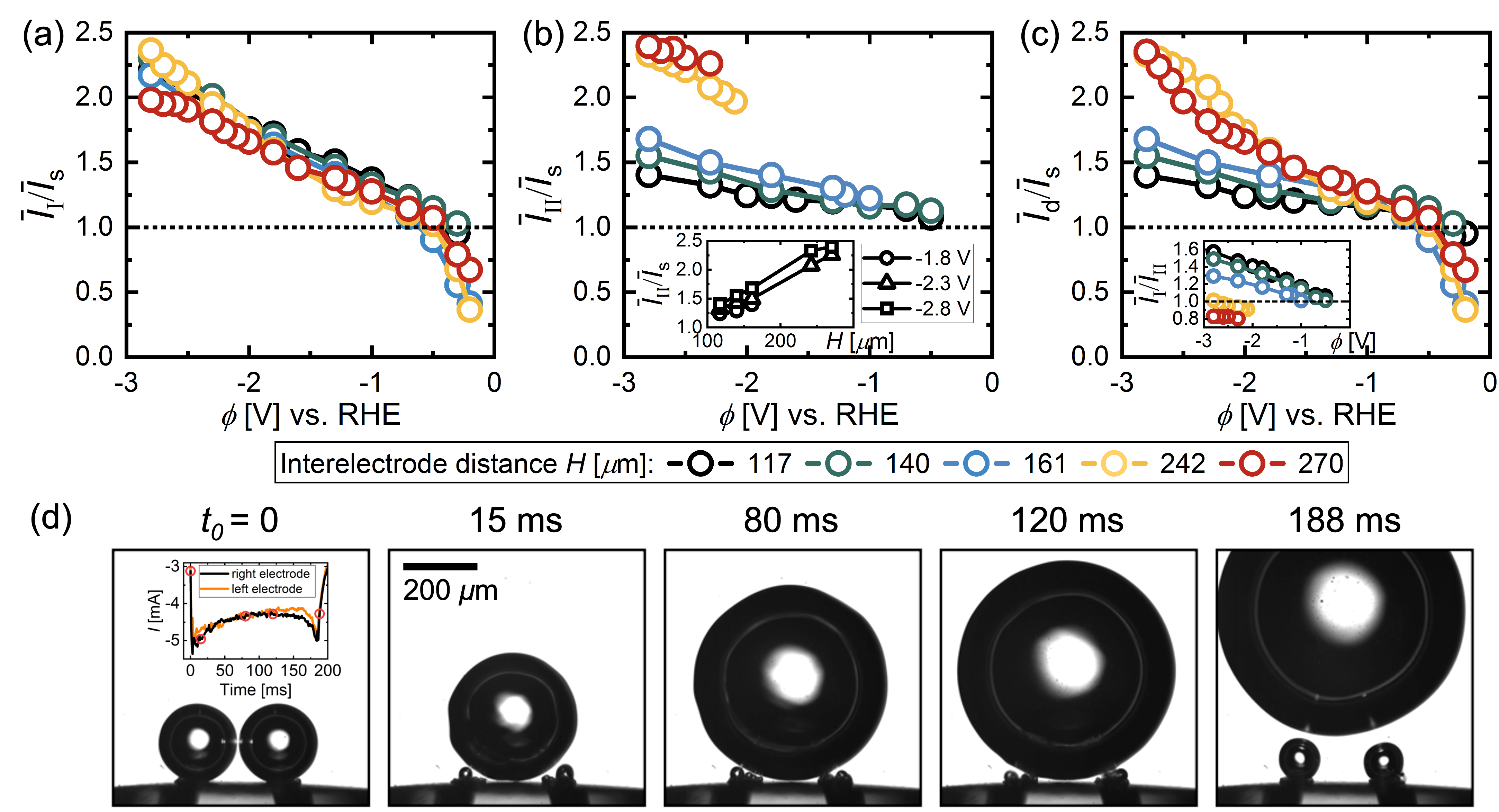
To quantify the performance gain and to compensate for the dependence of the current, we normalise the current on the dual electrode by . This also accounts for small differences in between the different electrodes used in this study (see Supporting Information). In figure 7a, the ratio is plotted for different as a function of . As the figure shows, the interference effects at low overpotentials already discussed in the context of figure 3, cause to even fall below for V. This does not improve noticeably for larger electrode spacing, presumably due to a trade-off between reduced interference effects and the increase in the bubble size with . For larger overpotentials, the benefits of the enhanced gas removal prevail, reflected in a ratio which also consistently increases with increased overpotential exceeding a value of 2 at V. Approximately the same values are also encountered for this potential for the ratio in figure 7b. While the performance in mode II also improves slightly for higher overpotential, it most strongly depends on . As the inset in figure 7b shows, the ratio increases approximately linearly with at constant potential.
Finally, figure 7c shows how the resulting effective current on the dual electrode changes relative to . In addition to variations in and , this quantity is also influenced by the probability of bubble return (mode II). Given the results in figure 5a, the ratio is therefore dominated by mode I at low and by mode II at large overpotentials. This implies that the performance gains in mode I at high are not practically realisable. However, this is only a limitation at smaller electrode separations, since the current in mode II even exceeds that of mode I for m and m (see inset of figure 7c). For these cases, the mode transition is therefore even beneficial.
Figure 7d shows snapshots for the parameter combination m and V for which the highest ratio was observed. Having the returned bubble located at the center in between the electrodes avoids the formation of larger bubbles directly on the electrodes. Notably, only a slight drop in the current is observed (see inset at ) as the outline of the bubble moves beyond the electrode positions. This contradicts the common practice of considering the region under the bubble as inactive but is in line with earlier conjectures.70, 31
4.4 Conclusions
We have explored the coalescence dynamics of electrogenerated bubbles and their influence on the electrochemical reaction rate using dual platinum micro-electrodes. We found that the coalescence of two adjacent bubbles leads to an initial jump-off of the merged bubble and premature escape from the surface. However, the continued coalescence with newly formed successors may result in a return to the electrode, hence prolonged growth. The latter mode is increasingly prevalent the higher the current and the smaller the interelectrode distance. We proposed a simple model to capture these trends and predict the critical magnitude of the current required to initiate the return process. This comeback mode negates the potential performance improvement achieved through direct departure following the coalescence event at smaller (up to a 1.7- vs. 2.3-fold increase in current at constant potential when compared to a single electrode). However, even in cases of bubble return, the effective current at larger increased by up to 2.4 times because the bubble was then located between the electrodes, exposing a greater electrode area for the reaction. Therefore, this mode is promising, especially since, given the dependence on electrode separation, even greater performance gains can be expected by further increasing . In practice, a similar configuration may be achieved on extended electrodes using hydrophobic islands, which should be spaced to favour coalescence-based departure and minimize the probability of bubble return, thus avoiding the blocking of the active surface area.
5 Conflicts of interest
There are no conflicts to declare.
6 Acknowledgements
This research received funding from the Dutch Research Council (NWO) with a co-funding acquired from Nobian and Helmholtz-Zentrum Dresden-Rossendorf (HZDR) in the framework of ElectroChemical Conversion and Materials (ECCM) KICkstart DE-NL (KICH1.ED04.20.009). S.P. acknowledges the support by Basic Science Research Program through the National Research Foundation of Korea (NRF) funded by the Ministry of Education (2021R1A6A3A14039678). D.K., D.L. and M.T.M.K. received funding from the European Research Council (ERC) (BU-PACT grant agreement number 950111, ERC Advanced grant number 740479-DDD and ERC Advanced Grant ‘FRUMKIN’ number 101019998, respectively). We thank V. Sanjay for insightful discussions on the subject.
References
- Brandon and Kurban 2017 Brandon, N. P.; Kurban, Z. Clean energy and the hydrogen economy. Philosophical Transactions of the Royal Society A: Mathematical, Physical and Engineering Sciences 2017, 375, 20160400
- Staffell et al. 2019 Staffell, I.; Scamman, D.; Abad, A. V.; Balcombe, P.; Dodds, P. E.; Ekins, P.; Shah, N.; Ward, K. R. The role of hydrogen and fuel cells in the global energy system. Energy & Environmental Science 2019, 12, 463–491
- Dawood et al. 2020 Dawood, F.; Anda, M.; Shafiullah, G. Hydrogen production for energy: An overview. International Journal of Hydrogen Energy 2020, 45, 3847–3869
- Lee et al. 2020 Lee, J. K.; Lee, C.; Fahy, K. F.; Kim, P. J.; Krause, K.; LaManna, J. M.; Baltic, E.; Jacobson, D. L.; Hussey, D. S.; Bazylak, A. Accelerating bubble detachment in porous transport layers with patterned through-pores. ACS Applied Energy Materials 2020, 3, 9676–9684
- Swiegers et al. 2021 Swiegers, G. F.; Terrett, R. N.; Tsekouras, G.; Tsuzuki, T.; Pace, R. J.; Stranger, R. The prospects of developing a highly energy-efficient water electrolyser by eliminating or mitigating bubble effects. Sustainable Energy & Fuels 2021, 5, 1280–1310
- Yu et al. 2022 Yu, S.; Li, K.; Wang, W.; Xie, Z.; Ding, L.; Kang, Z.; Wrubel, J.; Ma, Z.; Bender, G.; Yu, H.; others Tuning Catalyst Activation and Utilization Via Controlled Electrode Patterning for Low-Loading and High-Efficiency Water Electrolyzers. Small 2022, 18, 2107745
- Yuan et al. 2023 Yuan, S.; Zhao, C.; Cai, X.; An, L.; Shen, S.; Yan, X.; Zhang, J. Bubble evolution and transport in PEM water electrolysis: Mechanism, impact, and management. Progress in Energy and Combustion Science 2023, 96, 101075
- Zhao et al. 2019 Zhao, X.; Ren, H.; Luo, L. Gas bubbles in electrochemical gas evolution reactions. Langmuir 2019, 35, 5392–5408
- Angulo et al. 2020 Angulo, A.; van der Linde, P.; Gardeniers, H.; Modestino, M.; Rivas, D. F. Influence of bubbles on the energy conversion efficiency of electrochemical reactors. Joule 2020, 4, 555–579
- Angulo et al. 2022 Angulo, A. E.; Frey, D.; Modestino, M. A. Understanding bubble-induced overpotential losses in multiphase flow electrochemical reactors. Energy & Fuels 2022, 36, 7908–7914
- Shih et al. 2022 Shih, A. J.; Monteiro, M. C.; Dattila, F.; Pavesi, D.; Philips, M.; da Silva, A. H.; Vos, R. E.; Ojha, K.; Park, S.; van der Heijden, O.; others Water electrolysis. Nature Reviews Methods Primers 2022, 2, 84
- He et al. 2023 He, Y.; Cui, Y.; Zhao, Z.; Chen, Y.; Shang, W.; Tan, P. Strategies for bubble removal in electrochemical systems. Energy Reviews 2023, 100015
- Gross et al. 2021 Gross, S. J.; McDevitt, K. M.; Mumm, D. R.; Mohraz, A. Mitigating bubble traffic in gas-evolving electrodes via spinodally derived architectures. ACS Applied Materials & Interfaces 2021, 13, 8528–8537
- Tang et al. 2022 Tang, Z.; Wang, P.; Xu, B.; Meng, L.; Jiang, L.; Liu, H. Bioinspired Robust Water Repellency in High Humidity by Micro-meter-Scaled Conical Fibers: Toward a Long-Time Underwater Aerobic Reaction. Journal of the American Chemical Society 2022, 144, 10950–10957
- Krause et al. 2023 Krause, L.; Skibińska, K.; Rox, H.; Baumann, R.; Marzec, M. M.; Yang, X.; Mutschke, G.; Żabiński, P.; Lasagni, A. F.; Eckert, K. Hydrogen Bubble Size Distribution on Nanostructured Ni Surfaces: Electrochemically Active Surface Area Versus Wettability. ACS Applied Materials & Interfaces 2023, 15, 18290–18299
- Nam et al. 2011 Nam, Y.; Aktinol, E.; Dhir, V. K.; Ju, Y. S. Single bubble dynamics on a superhydrophilic surface with artificial nucleation sites. International Journal of Heat and Mass Transfer 2011, 54, 1572–1577
- Lu et al. 2014 Lu, Z.; Zhu, W.; Yu, X.; Zhang, H.; Li, Y.; Sun, X.; Wang, X.; Wang, H.; Wang, J.; Luo, J.; others Ultrahigh hydrogen evolution performance of under-water “superaerophobic” MoS2 nanostructured electrodes. Advanced Materials 2014, 26, 2683–2687
- Li et al. 2015 Li, Y.; Zhang, H.; Xu, T.; Lu, Z.; Wu, X.; Wan, P.; Sun, X.; Jiang, L. Under-water superaerophobic pine-shaped Pt nanoarray electrode for ultrahigh-performance hydrogen evolution. Advanced Functional Materials 2015, 25, 1737–1744
- Hao et al. 2016 Hao, J.; Yang, W.; Huang, Z.; Zhang, C. Superhydrophilic and superaerophobic copper phosphide microsheets for efficient electrocatalytic hydrogen and oxygen evolution. Advanced Materials Interfaces 2016, 3, 1600236
- Iwata et al. 2021 Iwata, R.; Zhang, L.; Wilke, K. L.; Gong, S.; He, M.; Gallant, B. M.; Wang, E. N. Bubble growth and departure modes on wettable/non-wettable porous foams in alkaline water splitting. Joule 2021, 5, 887–900
- Andaveh et al. 2022 Andaveh, R.; Darband, G. B.; Maleki, M.; Rouhaghdam, A. S. Superaerophobic/superhydrophilic surfaces as advanced electrocatalysts for the hydrogen evolution reaction: a comprehensive review. Journal of Materials Chemistry A 2022, 10, 5147–5173
- Cheng et al. 2023 Cheng, X.; Du, Z.-d.; Ding, Y.; Li, F.-y.; Hua, Z.-s.; Liu, H. Bubble Management for Electrolytic Water Splitting by Surface Engineering: A Review. Langmuir 2023,
- Winther-Jensen et al. 2012 Winther-Jensen, O.; Chatjaroenporn, K.; Winther-Jensen, B.; MacFarlane, D. R. Towards hydrogen production using a breathable electrode structure to directly separate gases in the water splitting reaction. International Journal of Hydrogen Energy 2012, 37, 8185–8189
- Tiwari et al. 2019 Tiwari, P.; Tsekouras, G.; Wagner, K.; Swiegers, G. F.; Wallace, G. G. A new class of bubble-free water electrolyzer that is intrinsically highly efficient. International Journal of Hydrogen Energy 2019, 44, 23568–23579
- Tsekouras et al. 2021 Tsekouras, G.; Terrett, R.; Yu, Z.; Cheng, Z.; Swiegers, G. F.; Tsuzuki, T.; Stranger, R.; Pace, R. J. Insights into the phenomenon of ‘bubble-free’ electrocatalytic oxygen evolution from water. Sustainable Energy & Fuels 2021, 5, 808–819
- Hodges et al. 2022 Hodges, A.; Hoang, A. L.; Tsekouras, G.; Wagner, K.; Lee, C.-Y.; Swiegers, G. F.; Wallace, G. G. A high-performance capillary-fed electrolysis cell promises more cost-competitive renewable hydrogen. Nature Communications 2022, 13, 1304
- Kadyk et al. 2016 Kadyk, T.; Bruce, D.; Eikerling, M. How to Enhance Gas Removal from Porous Electrodes? Scientific Reports 2016, 6
- Teschke and Galembeck 1983 Teschke, O.; Galembeck, F. A New Type of Separator for High Temperature Water Electrolyzers. Journal of The Electrochemical Society 1983, 130, 33–36
- Teschke and Galembeck 1984 Teschke, O.; Galembeck, F. Effect of PTFE Coverage on the Performance of Gas Evolving Electrodes. Journal of The Electrochemical Society 1984, 131, 1095–1097
- Brussieux et al. 2011 Brussieux, C.; Viers, P.; Roustan, H.; Rakib, M. Controlled electrochemical gas bubble release from electrodes entirely and partially covered with hydrophobic materials. Electrochimica Acta 2011, 56, 7194–7201
- Lake et al. 2022 Lake, J. R.; Soto, Á. M.; Varanasi, K. K. Impact of Bubbles on Electrochemically Active Surface Area of Microtextured Gas-Evolving Electrodes. Langmuir 2022, 38, 3276–3283
- Matsushima et al. 2003 Matsushima, H.; Nishida, T.; Konishi, Y.; Fukunaka, Y.; Ito, Y.; Kuribayashi, K. Water electrolysis under microgravity: Part 1. Experimental technique. Electrochimica Acta 2003, 48, 4119–4125
- Zhou et al. 2018 Zhou, J.; Zhang, Y.; Wei, J. A modified bubble dynamics model for predicting bubble departure diameter on micro-pin-finned surfaces under microgravity. Applied Thermal Engineering 2018, 132, 450–462
- Brinkert et al. 2018 Brinkert, K.; Richter, M. H.; Akay, Ö.; Liedtke, J.; Giersig, M.; Fountaine, K. T.; Lewerenz, H.-J. Efficient solar hydrogen generation in microgravity environment. Nature Communications 2018, 9, 2527
- Akay et al. 2022 Akay, Ö.; Bashkatov, A.; Coy, E.; Eckert, K.; Einarsrud, K. E.; Friedrich, A.; Kimmel, B.; Loos, S.; Mutschke, G.; Röntzsch, L.; others Electrolysis in reduced gravitational environments: current research perspectives and future applications. npj Microgravity 2022, 8, 56
- Akay et al. 2022 Akay, Ö.; Poon, J.; Robertson, C.; Abdi, F. F.; Cuenya, B. R.; Giersig, M.; Brinkert, K. Releasing the bubbles: nanotopographical electrocatalyst design for efficient photoelectrochemical hydrogen production in microgravity environment. Advanced Science 2022, 9, 2105380
- Raza et al. 2023 Raza, M. Q.; Köckritz, M. v.; Sebilleau, J.; Colin, C.; Zupancic, M.; Bucci, M.; Troha, T.; Golobic, I. Coalescence-induced jumping of bubbles in shear flow in microgravity. Physics of Fluids 2023, 35
- Bashkatov et al. 2021 Bashkatov, A.; Yang, X.; Mutschke, G.; Fritzsche, B.; Hossain, S. S.; Eckert, K. Dynamics of single hydrogen bubbles at Pt microelectrodes in microgravity. Physical Chemistry Chemical Physics 2021, 23, 11818–11830
- Janssen and Hoogland 1970 Janssen, L. J.; Hoogland, J. The effect of electrolytically evolved gas bubbles on the thickness of the diffusion layer. Electrochimica Acta 1970, 15, 1013–1023
- Sides and Tobias 1985 Sides, P. J.; Tobias, C. W. A close view of gas evolution from the back side of a transparent electrode. Journal of the Electrochemical Society 1985, 132, 583
- Hashemi et al. 2019 Hashemi, S. M. H.; Karnakov, P.; Hadikhani, P.; Chinello, E.; Litvinov, S.; Moser, C.; Koumoutsakos, P.; Psaltis, D. A versatile and membrane-less electrochemical reactor for the electrolysis of water and brine. Energy & Environmental Science 2019, 12, 1592–1604
- Ikeda et al. 2023 Ikeda, H.; Misumi, R.; Nishiki, Y.; Kuroda, Y.; Mitsushima, S. tert-Butyl-alcohol-induced breakage of the rigid bubble layer that causes overpotential in the oxygen evolution reaction during alkaline water electrolysis. Electrochimica Acta 2023, 452, 142283
- Westerheide and Westwater 1961 Westerheide, D. E.; Westwater, J. Isothermal growth of hydrogen bubbles during electrolysis. AIChE Journal 1961, 7, 357–362
- Bashkatov et al. 2022 Bashkatov, A.; Hossain, S. S.; Mutschke, G.; Yang, X.; Rox, H.; Weidinger, I. M.; Eckert, K. On the growth regimes of hydrogen bubbles at microelectrodes. Physical Chemistry Chemical Physics 2022, 24, 26738–26752
- Park et al. 2023 Park, S.; Liu, L.; Demirkır, Ç.; van der Heijden, O.; Lohse, D.; Krug, D.; Koper, M. T. Solutal Marangoni effect determines bubble dynamics during electrocatalytic hydrogen evolution. Nature Chemistry 2023, 1–9
- Yang et al. 2015 Yang, X.; Karnbach, F.; Uhlemann, M.; Odenbach, S.; Eckert, K. Dynamics of single hydrogen bubbles at a platinum microelectrode. Langmuir 2015, 31, 8184–8193
- Bashkatov et al. 2019 Bashkatov, A.; Hossain, S. S.; Yang, X.; Mutschke, G.; Eckert, K. Oscillating hydrogen bubbles at Pt microelectrodes. Physical Review Letters 2019, 123, 214503
- Kristof and Pritzker 1997 Kristof, P.; Pritzker, M. Effect of electrolyte composition on the dynamics of hydrogen gas bubble evolution at copper microelectrodes. Journal of Applied Electrochemistry 1997, 27, 255–265
- Brandon and Kelsall 1985 Brandon, N.; Kelsall, G. Growth kinetics of bubbles electrogenerated at microelectrodes. Journal of Applied Electrochemistry 1985, 15, 475–484
- Fernandez et al. 2014 Fernandez, D.; Maurer, P.; Martine, M.; Coey, J.; Möbius, M. E. Bubble formation at a gas-evolving microelectrode. Langmuir 2014, 30, 13065–13074
- Massing et al. 2019 Massing, J.; Mutschke, G.; Baczyzmalski, D.; Hossain, S. S.; Yang, X.; Eckert, K.; Cierpka, C. Thermocapillary convection during hydrogen evolution at microelectrodes. Electrochimica Acta 2019, 297, 929–940
- Hossain et al. 2020 Hossain, S. S.; Mutschke, G.; Bashkatov, A.; Eckert, K. The thermocapillary effect on gas bubbles growing on electrodes of different sizes. Electrochimica Acta 2020, 353, 136461
- Babich et al. 2023 Babich, A.; Bashkatov, A.; Yang, X.; Mutschke, G.; Eckert, K. In-situ measurements of temperature field and Marangoni convection at hydrogen bubbles using schlieren and PTV techniques. International Journal of Heat and Mass Transfer 2023, 215, 124466
- Zhan et al. 2023 Zhan, S.; Yuan, R.; Wang, X.; Zhang, W.; Yu, K.; Li, B.; Wang, Z.; Wang, J. Dynamics of growth and detachment of single hydrogen bubble on horizontal and vertical microelectrode surfaces considering liquid microlayer structure in water electrolysis. Physics of Fluids 2023, 35
- Meulenbroek et al. 2021 Meulenbroek, A.; Vreman, A.; Deen, N. Competing Marangoni effects form a stagnant cap on the interface of a hydrogen bubble attached to a microelectrode. Electrochimica Acta 2021, 385, 138298
- Perez Sirkin et al. 2019 Perez Sirkin, Y. A.; Gadea, E. D.; Scherlis, D. A.; Molinero, V. Mechanisms of nucleation and stationary states of electrochemically generated nanobubbles. Journal of the American Chemical Society 2019, 141, 10801–10811
- Chen et al. 2015 Chen, Q.; Wiedenroth, H. S.; German, S. R.; White, H. S. Electrochemical nucleation of stable N2 nanobubbles at Pt nanoelectrodes. Journal of the American Chemical Society 2015, 137, 12064–12069
- German et al. 2018 German, S. R.; Edwards, M. A.; Ren, H.; White, H. S. Critical nuclei size, rate, and activation energy of H2 gas nucleation. Journal of the American Chemical Society 2018, 140, 4047–4053
- Sepahi et al. 2023 Sepahi, F.; Verzicco, R.; Lohse, D.; Krug, D. Mass transport at gas-evolving electrodes. 2023
- Young et al. 1959 Young, N.; Goldstein, J. S.; Block, M. The motion of bubbles in a vertical temperature gradient. Journal of Fluid Mechanics 1959, 6, 350–356
- Guelcher et al. 1998 Guelcher, S. A.; Solomentsev, Y. E.; Sides, P. J.; Anderson, J. L. Thermocapillary phenomena and bubble coalescence during electrolytic gas evolution. Journal of The Electrochemical Society 1998, 145, 1848
- Lubetkin 2003 Lubetkin, S. Thermal Marangoni effects on gas bubbles are generally accompanied by solutal Marangoni effects. Langmuir 2003, 19, 10774–10778
- Yang et al. 2018 Yang, X.; Baczyzmalski, D.; Cierpka, C.; Mutschke, G.; Eckert, K. Marangoni convection at electrogenerated hydrogen bubbles. Physical Chemistry Chemical Physics 2018, 20, 11542–11548
- Soto et al. 2018 Soto, Á. M.; Maddalena, T.; Fraters, A.; Van Der Meer, D.; Lohse, D. Coalescence of diffusively growing gas bubbles. Journal of Fluid Mechanics 2018, 846, 143–165
- Lv et al. 2021 Lv, P.; Peñas, P.; Eijkel, J.; Van Den Berg, A.; Zhang, X.; Lohse, D.; others Self-propelled detachment upon coalescence of surface bubbles. Physical Review Letters 2021, 127, 235501
- Sanjay et al. 2021 Sanjay, V.; Lohse, D.; Jalaal, M. Bursting bubble in a viscoplastic medium. Journal of Fluid Mechanics 2021, 922, A2
- Thorncroft and Klausner 2001 Thorncroft, G. E.; Klausner, J. F. Bubble forces and detachment models. Multiphase Science and Technology 2001, 13
- Favre et al. 2023 Favre, L.; Colin, C.; Pujet, S.; Mimouni, S. An updated force balance approach to investigate bubble sliding in vertical flow boiling at low and high pressures. International Journal of Heat and Mass Transfer 2023, 211, 124227
- Hossain et al. 2022 Hossain, S. S.; Bashkatov, A.; Yang, X.; Mutschke, G.; Eckert, K. Force balance of hydrogen bubbles growing and oscillating on a microelectrode. Physical Review E 2022,
- Pande et al. 2019 Pande, N.; Mul, G.; Lohse, D.; Mei, B. Correlating the short-time current response of a hydrogen evolving nickel electrode to bubble growth. Journal of The Electrochemical Society 2019, 166, E280