Creating pair plasmas with observable collective effects
Abstract
Although existing technology cannot yet directly produce fields at the Schwinger level, experimental facilities can already explore strong-field QED phenomena by taking advantage of the Lorentz boost of energetic electron beams. Recent studies show that QED cascades can create electron-positron pairs at sufficiently high density to exhibit collective plasma effects. Signatures of the collective pair plasma effects can appear in exquisite detail through plasma-induced frequency upshifts and chirps in the laser spectrum. Maximizing the magnitude of the QED plasma signature demands high pair density and low pair energy, which suits the configuration of colliding an over energy-density electron beam with a intensity laser pulse. The collision creates pairs that have a large plasma frequency, made even larger as they slow down or reverse direction due to both the radiation reaction and laser pressure. This paper explains at a tutorial level the key properties of the QED cascades and laser frequency upshift, and at the same time finds the minimum parameters that can be used to produce observable QED plasma.
1 Introduction
According to QED theory, when the field exceeds the Schwinger limit [1] , the quantum vacuum becomes unstable and it spontaneously creates pairs of electrons and positrons. The oppositely charged electrons and positrons at high density naturally lead to collective plasma effects in the so-called “QED plasma” regime [2, 3, 4, 5, 6, 7]. QED plasma effects dominate in astrophysical environments like near a black hole [8] or magnetar [9, 10]. Our current understanding of these environments [11] is based upon strong-field QED theory for pair creation and plasma theory for the subsequent pair-pair interactions. However, to accurately describe how the QED pair plasmas emit observable radiation and affect the information delivery in the cosmological horizon, it is critical to address how the collective plasma and strong-field QED processes interplay.
Recent progress in the study of QED physics has been stimulated by the advances of high-power laser technology. Since the invention of chirped-pulse amplification [12, 13, 14], the record laser intensity [15] has grown steadily from to . Although the latter number is still six orders of magnitude lower than needed for providing , we can bridge the gap by colliding the laser with an energetic electron beam. The ultra-relativistic electrons boost the laser field by orders of magnitude in the electron rest frame, making it possible for existing lasers to test quantum effects. Applying this method, the seminal Stanford E-144 experiment [16, 17] in the 1990s detected evidence of positron creation using a laser colliding with a near electron beam. The quantum nonlinearity parameter, defined as the ratio of the field to the critical field, is ( is measured in the electron rest frame) for this experiment. Two decades later, the Gemini laser facility [18, 19] employed a laser pulse colliding with a GeV electron beam, created via laser wakefield acceleration (LWFA), to observe signatures of quantum radiation reaction at . The commissioned E-320 experiment [20] is designed to extend the Stanford experiment and collide a laser with electron beam to reach .
While the community is focusing on testing QED effects at the single particle level, we note that the technology for accessing the QED plasma regime is, in fact, already available [6, 7]. Suppose we can colocate a laser with the electron beam at SLAC [21, 22], then the parameter reaches which is sufficient to produce a QED cascade [23, 24, 25, 26, 27, 28, 29, 30, 31, 32, 33, 34]. Such a cascade, shown in recent numerical simulations [6, 7], creates pairs at sufficiently high density and low energy that the collective plasma effects begin to show signatures during the laser-pair interaction.
However, creating a QED plasma and probing its collective effects, while technically possible, is not so simple. First, the created pairs gain high energy either directly from the gamma photons which they decay from or from the strong laser field. The high pair energy means an increased relativistic mass which significantly suppresses their contribution to collective plasma effects. Second, even with extreme parameters such as a laser and a , electron beam, the created pair plasma only has a charge of distributed in micron scale. The low charge number and small volume prohibit the onset of most plasma instabilities. Third, the pair particles are subject to the ponderomotive force of the intense laser and they undergo rapid volume expansion. Already traveling at relativistic speeds, pair particles last as a plasma within the laser only for picoseconds as numerically demonstrated in [6, 7].
Thus, detecting the subtle collective effects of QED plasma requires methods that are sensitive and robust. In views of the aforementioned challenges, we suggest [6, 7] employing a laser to collide with a dense high energy electron beam. The induced QED cascade can not only produce pairs at high density but also low energy. Both properties contribute to strong collective plasma effects. More importantly, the laser pulse, while creating the QED cascade, also probes the time varying pair plasma through the induced frequency change [35, 36, 37, 38, 39, 40, 41, 42, 43, 44, 45, 46, 47]. The laser frequency upshift, determined solely by the change of plasma frequency, provides a robust and unambiguous signature of the collective plasma effects.
In this paper, we will elaborate on the joint production-observation problem of collective effects of QED plasmas. We analyze the available technologies and assess their advantages for producing high-density and low-energy pair plasma. In Sec. 2, we compare the laser-laser collision approach and the beam-laser collision approach for creating plasma and for reducing the relativistic boost of the pair mass. In Sec. 3, we find the condition on energy density of the electron beam that can create an observable pair plasma. For providing the electron beam, we show the availability of existing conventional electron beam facilities and the promise of the LWFA method at high-power laser facilities. In Sec. 4, we explain in detail how the laser frequency spectrum changes in a time-varying plasma and derive the amount of laser frequency upshift. In Sec. 5, we present our conclusion.
2 Reducing the pair energy for strong plasma signatures
The plasma frequency is determined by both the pair density and pair energy (proportional to its Lorentz factor ): , where is the natural charge, is the vacuum permittivity, and is the pair rest mass. It is thus key to prepare QED pairs at low energy for detecting their collective effects. Otherwise, high particle energy causes large pair mass from relativistic effects and would substantially suppress their collective response. The requirement of low pair energy seems to conflict with the QED condition that gamma photon emission takes place only with high energy particles. This is true with the laser-laser collision approach for reaching the QED regime, but the conflict is avoided in an electron-beam driven QED cascade.
2.1 Laser-laser collision cascade
A laser-laser collision approach of QED cascade, also referred to as the “avalanche-type” cascade, employs two ultra-intense counterpropagating laser pulses overlapping in a region with stationary seed electrons [48, 49]. The strong laser beat wave accelerates the electrons to relativistic velocities. As the electron Lorentz factor increases, the laser field is boosted by an increasing factor to reach the quantum critical field. Once the quantum nonlinearity parameter reaches near unit value, the electrons begin to emit high energy gamma photons that can decay into electron-positron pairs. The pairs are then accelerated by the laser field to continue the QED process and develop into a cascade. This process is “self-sustained”, i.e., it terminates only when the pairs escape the laser focal region.
To reach the QED cascade condition, the laser-laser collision approach [3, 49] likely requires laser intensities, corresponding to laser amplitude , where is the laser frequency. If a pair plasma is created, the pair particles would be quickly accelerated to high energy with Lorentz factors . Thus, their contribution to the plasma frequency would be suppressed by a factor of at least . The smallness of their contribution means that detecting the collective plasma effects would need higher pair density which in turn requires even stronger lasers. Moreover, because of the high pair energy, the contribution of the pairs to the collective plasma effects could be less than that of the stationary seeding electrons unless the pair number multiplication factor is larger than .
2.2 Electron-beam driven cascade
In contrast to the laser-laser collision approach, the electrons in a beam-driven QED cascade begin with the maximum particle energy. Once the ramping-up laser intensity reaches (the factor of arises from the counterpropagating configuration), the electrons begin to emit gamma photons and lose significant energy. Electron-positron pairs are created by acquiring the energy of the emitted gamma photons. If the pairs have sufficiently high Lorentz factors, i.e., , they emit more gamma photons that can decay into more pairs. This process is thus also called the “shower-type” QED cascade. This type of cascade converts electron beam energy into pair particles during its collision with a strong laser. The laser pulse, however, does not contribute to the pair energy. The created pairs exhibit increasingly strong plasma behavior both when their density grows and when their energy decreases. This approach takes advantage of the high beam energy available through existing electron beam facilities; hence, it greatly reduces the required laser intensity. For example with electron beam energy, laser intensity could already reach and produce pair number multiplication. Higher laser intensity at , combined with the same electron beam, could reach the extreme quantum limit and induce a full-featured QED cascade [6, 7].
The low requirement for laser intensity not only avoids the technical challenges of building -class laser, but also allows the pairs to exhibit strong plasma effects. In the electron-beam driven cascade, the counterpropagating laser pulse decelerates the particles to reduce the pair energy. This means that the relativistic particle mass decreases and their contribution to the plasma frequency increases. The minimum pair energy (and hence the maximum contribution to plasma frequency) is achieved if the pairs could be fully stopped, at least, in the longitudinal direction. In the “pair-stopping” regime, the minimum pair energy is then determined solely by their transverse quiver motion driven by laser, and thus for .
Reaching the “pair-stopping” regime requires the laser amplitude to exceed the threshold value: corresponding to for -wavelength lasers. The threshold laser amplitude is obtained [6, 7] by analyzing the two dominating mechanisms of pair deceleration. The high energy pairs first lose energy mainly through the quantum radiation reaction which terminates when the pair energy decreases below the value for . Then the second mechanism—the ponderomotive force of the counterpropagating laser—begins to dominate the pair deceleration. The ponderomotive pressure can reduce the longitudinal electron momentum by the maximum amount of in the limit of a single laser wavelength [23], and this value is slightly larger for longer laser pulses [50]. These two mechanisms scale with differently. By equating the terminal pair energy for quantum radiation reaction and the maximum pair energy that can be exchanged with the laser field, we can find the threshold laser amplitude: . Above the threshold, the pair particles could be fully stopped reaching the minimum longitudinal momentum.
If the laser intensity substantially exceeds , some of the pair particles, if they remain near the laser center, could be reaccelerated by the strong ponderomotive force towards the laser beam direction. The reacceleration on one hand side increases the pair Lorentz factor, but on the other hand side also reduces the laser frequency in the copropagating pair rest frame. For the particular plasma signature of laser frequency upshift, it is shown [50] that reacceleration can accentuate the amount of frequency upshift by up to a factor of .
3 Reaching high pair density for large plasma effects
In an electron-beam driven QED cascade, all the pairs are created by converting the energy of either the electron beam or the pairs created by it, mediated by high energy gamma photons. Since the energy contribution from the laser and long-wavelength emissions are both negligible, the total particle energy is conserved during the cascade. In other words, the integrated particle energy-density over the whole space is conserved.
The conservation of integrated particle energy-density means that creating high density pair plasma requires employing a high energy-density electron beam. Quantitatively, the final pair density can be estimated as
| (1) |
where is the density of injected electrons and , interpreted as the pair multiplication factor, is the quantum nonlinearity parameter for the injected electron beam with in the laser field. This relation assumes that all the pair particles interact with constant laser intensity and the cascade terminates at when their emitted photons can no longer decay into more pairs. For -wavelength lasers, the relation can be written numerically as . Thus, for the cascade to create a pair density near the critical density , the electron beam needs to have energy density assuming that the laser reaches at the “pair-stopping” threshold amplitude ().
Note that, although employing a higher laser intensity can improve the pair multiplication factor, it does not increase the pair plasma frequency. Once the laser amplitude is above , the final pair motion becomes dominantly transverse with kinetic energy proportional to the laser amplitude. Higher laser amplitude simultaneously induces a larger pair multiplication factor and a larger Lorentz factor, canceling their contribution to the plasma frequency .
The required high energy-density naturally favors conventional accelerators for their high luminosity. For GeV-level electron beam energy, the density needs to reach . For example, the nC-level electron charge is accessible in several electron accelerator facilities including SLAC, eRHIC, ILC, CLIC, etc. Taking into account the beam bunch size, their electron densities all exceed . Notably, their beam energy are in the range of to TeV level enabling .
Laser wakefield acceleration is an alternative technique which yields hundreds-of-MeV to GeV-level electron beams at high-power laser facilities. It uses the ponderomotive force of a strong laser pulse to push electrons in a plasma medium via either self-modulated beat wave or a hollow bubble. Present LWFA techniques, however, have the major drawback of a trade-off between high beam energy or high charge number. The current record [51] for LWFA electron energy is , but it only has total charge. The energy density of this electron beam is still three orders of magnitude lower than the required value. Higher charge number could be achieved only by compromising the beam length and more importantly the beam energy, which both reduce the energy density. Recent studies [52, 53, 54, 55] show via numerical simulation that long-wavelength CO2 lasers at high power might overcome the energy-density barrier and produce high electron charge number at the GeV level through LWFA. Nevertheless, producing of electrons at , which contains electron kinetic energy, will need next generation laser technology capable of delivering laser pulses even at energy conversion efficiency.
4 Laser frequency upshift induced by plasma effects
If a pair plasma were created through the QED cascade as we described above, it would be micrometer sized with relativistic velocity making diagnosing it challenging. Detecting the subtle collective effects needs unconventional methods that are sensitive and robust. One of the lowest order plasma effects is the dispersion relation. As the pair plasma is formed, the plasma frequency grows both when the pair density increases and when the pair energy decreases. The growing plasma frequency changes the dispersion relation of laser by reducing the refractive index and increasing the laser phase velocity. Sudden creation of plasma over space amounts to a temporal interface of refractive indices, through which the laser frequency is upshifted. Considering that the pair plasma dimension is only a fraction of the laser duration, the increased laser phase velocity also causes its wavefront to compress towards the front which can be detected as a chirp in the laser spectrum. Both the laser frequency upshift and chirp arise from the temporal evolution of the plasma frequency, hence they serve as unambiguous signatures of collective effects.
The creation of pair plasma is modeled as a temporal interface of refractive indices, which is known to cause laser frequency upshift [56, 57, 58, 59, 40]. The frequency upshift process [36, 37, 38, 41, 42, 43, 44, 45, 46, 47] is analogous to the trivial process of laser wavelength shift when crossing a spatial interface of refractive index. The concept of laser frequency change in dynamic media was first studied [35] by Morgenthaler in 1958. With rapidly growing laser technology in the 1970s, it is found [60, 61, 62] that laser-breakdown plasmas can serve as such dynamic media. The concept was further developed as, so-called, “photon accelerators” [63, 64, 65, 66, 39], in which the laser propagates in the rear edge of a plasma wave wakefield. Since the laser co-moves in a positive density gradient, it can be frequency upconverted continuously. Using laser-induced ionization, frequency upconversion has been experimentally demonstrated in the microwave [67, 68, 69, 66, 70], terahertz [43] and optical [71, 72] regimes.
In a QED cascade, the created pair plasma interacts with the laser in a manner similar to an ionization front but in a counterpropagating geometry. It changes the refractive index in both space and time, and leads to changes in both laser frequency and wavelength. In the following, we will first pictorially explain the change of laser spectrum using a spacetime diagram and then analytically derive the amount of upshift due to the transient and inhomogeneous pair plasma.
4.1 Diagram explanation of laser frequency upshift
Laser propagation can be illustrated using the spacetime diagram, as shown in figure 1. The shaded area in figure 1 represents pair plasma which grows in time and expands in space. The parallel lines represent the laser wavefront propagating in the -direction. The vertical and horizontal spacings of the lines correspond to the laser frequency and wavevector, respectively. As the laser propagates through the vacuum-plasma interface, its phase velocity changes from to . The phase of the laser is nevertheless continuous across the interface, represented as non-broken lines in figure 1.
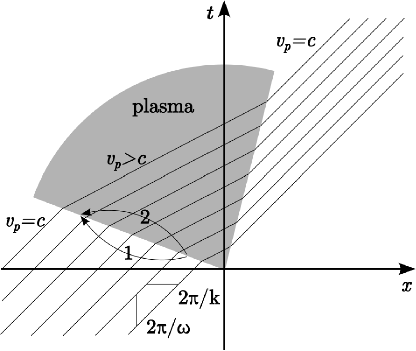
The change of laser frequency and wavenumber results from both the change of phase velocity, denoted as the slope change of the parallel lines in figure 1, and the angle of interface. The interface can be categorized in the following types depending on its angle:
-
1.
A spatial interface of media is represented by a vertical boundary parallel to the -axis in spacetime diagram. The laser wavefront when crossing the spatial interface conserves its vertical spacing, i.e., its frequency; its horizontal spacing changes correspondingly, indicating a change in wavenumber.
-
2.
A temporal interface of media is represented by a horizontal boundary parallel to the -axis in spacetime diagram. The laser wavefront when crossing it conserves its horizontal spacing but changes its vertical spacing, indicating a change in frequency.
-
3.
More generally, if the interface involves both spatial and temporal changes of refractive index, it is represented in the spacetime diagram by a boundary that is not parallel to either - or -axis, the laser wavefront spacing changes in both directions, indicating changes in both frequency and wavevector.
Because the laser phase is continuous, any separation on the interface has identical optical paths in both media, leading to the identity
| (2) |
where and are the frequency and wavevector in the ’th medium, and and are arbitrary spacetime distances on the interface. The slope of interface is most conveniently described by the parameter . The parameter can also be interpreted as the velocity of the interface. Then using the relation , we can obtain
| (3) | ||||
These relations describe how the frequency and wavevector change when the laser propagates through a spacetime interface moving at velocity . The shifts of frequency and wavevector can then be expressed as
| (4) | ||||
The process of interface crossing can take place either when the laser propagates faster than the interface () or when the interface overtakes the laser (). But the parameter regime () forbids laser propagation after it crosses the interface, and hence is nonphysical.
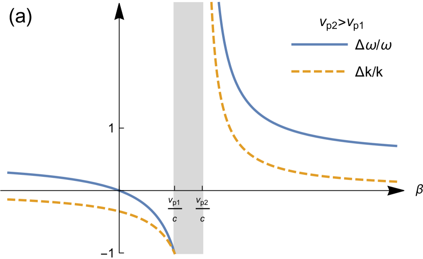
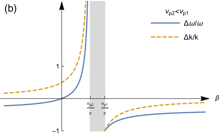
The amount of frequency shift () and wavevector shift () with varying interface velocity is plotted in figure 2 assuming, respectively, (a) and (b) . Depending on the relations of the interface and laser velocities, the plot can be divided into four regimes, among which the shaded areas are nonphysical.
A subluminal copropagating interface traverses through the laser pulse from the laser front to laser tail. If , the laser wavefront propagates faster after crossing the interface and it leads to an increase of wavelength and period. Thus, both the laser frequency and wavevector are downshifted. In the limit of , it reduces to a stationary interface which downshifts the laser wavevector by but does not change the laser frequency. As the interface velocity increases, the slower relative motion between the laser wavefront and the interface lengthens the wavefront spreading process, thereby amplifying the downshifts.
A superluminal copropagating interface traverses through the laser pulse from the laser tail to front. For , the faster phase velocity in the tail compresses the laser wavefront. It leads to a decrease of wavelength and period, and hence an upshift of laser frequency and wavevector. Similarly to a subluminal interface, a smaller relative interface-to-laser velocity lengthens the time of wavefront compression. Thus, the frequency and wavevector upshifts become greater as . In the case of a laser crossing a sudden and homogeneous interface , the spatial separation of the laser wavefront, or wavelength , does not change, i.e., , but the temporal separation is reduced from to so the frequency is upshifted by a factor .
A counterpropagating interface traverses through the laser pulse from the laser front to tail. Similar to the scenario of a subluminal copropagating interface, the laser wavefront, which has a faster phase velocity in the front, is lengthened. This causes a downshift of wavevector, . From the time point of view, the laser wavefronts in the counterpropagating configuration cross the interface at a rate higher than the laser frequency. This allows the laser tail to propagate more time at () than the front for the same distance, similar to the effect of a superluminal copropagating interface. Thus, the laser wavefront is compressed in time and the laser frequency is upshifted.
In an electron-beam driven QED cascade, the laser pulse crosses the vacuum-plasma interface twice, when entering and exiting the plasma. The first encounter occurs when the laser pulse and electron beam begin to collide. The pairs are initially created inside the electron beam and thus the vacuum plasma interface has the same Lorentz factor with the beam, i.e., . (The factor could locally exceed unit value considering the fact that the pair density spacetime gradient is determined by both the particle density and laser intensity. But the asymptotic speed of the pair plasma front equals to that of the electron beam.) If we assume a homogeneous plasma, the laser phase velocity changes from to after crossing the interface. According to (3), the laser frequency and wavevector change to and , respectively. The created pairs lose most of their energy and are subject to the ponderomotive potential of the strong laser pulse. As explained in the last section, the pairs are mostly stopped and partially reflected while expanding in transverse directions. Also, because the fast moving pairs have high energy and hence contribute little to the plasma frequency, we can describe the second plasma-vacuum interface with . Thus, the laser frequency does not change and the wavevector changes as Therefore, the vacuum-plasma-vacuum interfaces change the laser frequency and wavevector as
| (5) | ||||
Equations (5) show that the amount of laser frequency upshift is . It is lower than the laser frequency upshift in sudden “flash” ionization by a factor of caused by the finite velocity of the interface. The laser frequency change could be measurable if the pair plasma density needs to reach a non-negligible fraction of the laser frequency. Assuming laser amplitude , the pair density needs to reach .
4.2 Chirp of laser spectrum caused by QED cascade
The above analysis assumes homogeneous plasma frequency to obtain equation (5). However, the combined processes of pair creation and volume expansion cause the plasma density to be inhomogeneous in both space and time. We illustrate the interaction of the laser and pair plasma in figure 3. The diagram shows that as the laser pulse enters and exits the plasma-vacuum interfaces, each part of the laser pulse propagates through plasma at different velocities. Since only the laser center propagates through the densest part of plasma, it experiences the largest frequency and wavevector upshifts. Therefore, the laser pulse is chirped.
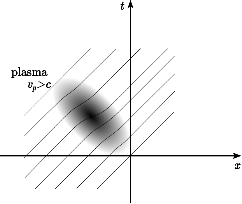
The chirp profile can be found by tracing the amount of phase shift when the laser propagates through the inhomogeneous plasma. Since the phase shift is different for each part of the laser pulse, it is convenient to define denoting the relative delay from the laser front and denoting the propagation time. The laser phase can then be written as . The expression in the coordinate separates the laser phase into its internal phase variation and the induced changes along . For laser propagating in vacuum, which is a constant along . If the laser propagates through plasma as shown in figure 3, the collective plasma effect causes a phase shift , which accumulates in . For small plasma frequencies, . Each part of laser at propagates through plasma at over the range . Thus, the total phase shift can be found as
| (6) |
Neglecting the small change of and transforming back to the coordinate, we have
| (7) |
The frequency and wavevector after propagating through inhomogeneous plasma can thus be expressed as
| (8) | ||||
| (9) |
Note that , so the dispersion relation is automatically verified. We can further simplify the expressions by noting that and , then we obtain the expressions reported in [6, 7]
| (10) | ||||
| (11) |
The expressions show a very intuitive picture: the change of laser frequency and wavevector are caused by the integration of temporal and spatial change of plasma frequency calculated at the retarded position . If the plasma moves with velocity , then and hence the amounts of frequency and wavevector upshift only differ by a factor of .
Because the laser chirp is related to the rapidness of the plasma frequency change , the signal could be much larger than the laser frequency shift for small plasma size. In the aforementioned QED cascade, the laser pulse has a typical duration of corresponding to in length, but the plasma only has length. Thus, the instantaneous laser frequency upshift could be several times higher than the central frequency change of the whole pulse. In other words, the pair plasma is created when the small electron beam encounters the most intense region of the laser pulse and hence only induces laser frequency upshift near its intensity peak. When averaging over the whole laser pulse, the frequency upshift would decrease by a large factor.
5 Conclusion
The QED plasma dynamics are distinguished from traditional electron-ion plasmas by a number of physical aspects, including special relativistic effects, radiation-reaction effects, and high mobility under laser pressure. Exploiting the laser frequency upshift relaxes the conditions for QED plasma detection. Thus, creating an observable pair plasma through strong-field QED cascades in terrestrial laboratories becomes possible with state-of-the-art technologies.
Adopting the electron-beam-laser collision approach, the minimum parameters for testing QED plasma phenomena include laser intensity of and electron beam energy density of (). The required energy density can be readily produced by a conventional electron beam accelerator. Its production at a strong laser facility might also become possible if the LWFA technique can overcome the trade-off between high beam energy and high total electron charge. If the high energy-density electron beam is colocated with a PW-class laser, the collision creates QED pairs with growing a density and decreasing energy. In contrast to the direct all-optical laser-laser collision approach, the electron-beam driven QED cascade converts high energy beam into pairs with low energy and high density, both of which contribute to higher plasma frequency. The use of a high energy electron beam reduces the required laser intensity. The lower laser intensity means that the produced pairs are less energetic, making the plasma frequency larger for the same pair density.
Identifying the conditions for creating observable QED plasma is timely in view of the present planning of QED facilities. With current technology, the highest quantum nonlinearity parameter is achieved using conventional electron accelerators. The undergoing Stanford E-320 experiment [20] uses a beam and a laser to achieve . The electron beam energy density, assuming that the beam can be compressed to size, could reach . Creating an observable QED plasma requires an upgrade of the laser by two order of magnitude, reaching . The LUXE experiment at DESY proposes [73] using a beam and to achieve . The beam at the highest energy configuration is limited to nC charge and fs length, hence it needs significant focusing to exhibit collective plasma effects.
Acknowledgments
This work was supported by DOE Grants DE-NA0003871, NNSA DE-SC0021248, and DE-AC02-76SF00515.
References
References
- [1] Schwinger J 1951 Phys. Rev. 82(5) 664
- [2] Uzdensky D A and Rightley S 2014 Rep. Prog. Phys 77 036902
- [3] Grismayer T, Vranic M, Martins J L, Fonseca R A and Silva L O 2016 Phys. Plasmas 23 056706
- [4] Uzdensky D, Begelman M, Beloborodov A, Blandford R, Boldyrev S, Cerutti B, Fiuza F, Giannios D, Grismayer T, Kunz M, Loureiro N, Lyutikov M, Medvedev M, Petropoulou M, Philippov A, Quataert E, Schekochihin A, Schoeffler K, Silva L, Sironi L, Spitkovsky A, Werner G, Zhdankin V, Zrake J and Zweibel E 2019
- [5] Zhang P, Bulanov S S, Seipt D, Arefiev A V and Thomas A G R 2020 Phys. Plasmas 27 050601
- [6] Qu K, Meuren S and Fisch N J 2021 Phys. Rev. Lett. 127(9) 095001
- [7] Qu K, Meuren S and Fisch N J 2022 Physics of Plasmas 29 042117
- [8] Ruffini R, Vereshchagin G and Xue S S 2010 Physics Reports 487 1–140 ISSN 0370-1573
- [9] Kaspi V M and Beloborodov A M 2017 Annu. Rev. Astron. Astrophys. 55 261
- [10] Cerutti B and Beloborodov A M 2017 Space Sci. Rev. 207 111
- [11] Zhang B 2020 Nature 587 45–53
- [12] Cartlidge E 2018 Science 359 382
- [13] Bromage J, Bahk S W, Begishev I A, Dorrer C, Guardalben M J, Hoffman B N, Oliver J B, Roides R G, Schiesser E M, Shoup III M J and et al 2019 High Power Laser Sci 7 e4
- [14] Danson C N, Haefner C, Bromage J, Butcher T, Chanteloup J C F, Chowdhury E A, Galvanauskas A, Gizzi L A, Hein J, Hillier D I and et al 2019 High Power Laser Sci. Eng. 7 e54
- [15] Yoon J W, Jeon C, Shin J, Lee S K, Lee H W, Choi I W, Kim H T, Sung J H and Nam C H 2019 Opt. Express 27 20412–20420
- [16] Bula C, McDonald K T, Prebys E J, Bamber C, Boege S, Kotseroglou T, Melissinos A C, Meyerhofer D D, Ragg W, Burke D L, Field R C, Horton-Smith G, Odian A C, Spencer J E, Walz D et al. 1996 Phys. Rev. Lett. 76 3116
- [17] Burke D L, Field R C, Horton-Smith G, Spencer J E, Walz D, Berridge S C, Bugg W M, Shmakov K, Weidemann A W, Bula C, McDonald K T, Prebys E J, Bamber C, Boege S J, Koffas T et al. 1997 Phys. Rev. Lett. 79 1626
- [18] Cole J M, Behm K T, Gerstmayr E et al. 2018 Phys. Rev. X 8 011020
- [19] Poder K, Tamburini M, Sarri G, Di Piazza A, Kuschel S, Baird C D, Behm K, Bohlen S, Cole J M, Corvan D J, Duff M, Gerstmayr E, Keitel C H, Krushelnick K, Mangles S P D et al. 2018 Phys. Rev. X 8 031004
- [20] Meuren S 2022 Light-matter interactions at extreme intensities and densities: reaching the Schwinger limit APS April Meeting Abstracts (APS Meeting Abstracts vol 2022) p H07.003
- [21] SLAC Site Office 2016 SLAC-R-1072
- [22] Meuren S, Bucksbaum P H, Fisch N J, Fiúza F, Glenzer S, Hogan M J, Qu K, Reis D A, White G and Yakimenko V 2020 On seminal hedp research opportunities enabled by colocating multi-petawatt laser with high-density electron beams
- [23] Di Piazza A, Müller C, Hatsagortsyan K Z and Keitel C H 2012 Rev. Mod. Phys. 84 1177
- [24] Sokolov I V, Naumova N M, Nees J A and Mourou G A 2010 Phys. Rev. Lett. 105 195005
- [25] Hu H, Müller C and Keitel C H 2010 Phys. Rev. Lett. 105 080401
- [26] Thomas A G R, Ridgers C P, Bulanov S S, Griffin B J and Mangles S P D 2012 Phys. Rev. X 2 041004
- [27] Neitz N and Di Piazza A 2013 Phys. Rev. Lett. 111 054802
- [28] Bulanov S S, Schroeder C B, Esarey E and Leemans W P 2013 Phys. Rev. A 87 062110
- [29] Blackburn T G, Ridgers C P, Kirk J G and Bell A R 2014 Phys. Rev. Lett. 112 015001
- [30] Green D G and Harvey C N 2014 Phys. Rev. Lett. 112 164801
- [31] Vranic M, Martins J L, Vieira J, Fonseca R A and Silva L O 2014 Phys. Rev. Lett. 113 134801
- [32] Blackburn T G, Ilderton A, Murphy C D and Marklund M 2017 Phys. Rev. A 96 022128
- [33] Vranic M, Klimo O, Korn G and Weber S 2018 Sci. Rep. 8 4702 ISSN 2045-2322
- [34] Magnusson J, Gonoskov A, Marklund M, Esirkepov T Z, Koga J K, Kondo K, Kando M, Bulanov S V, Korn G and Bulanov S S 2019 Phys. Rev. Lett. 122(25) 254801
- [35] Morgenthaler F R 1958 IEEE Trans. Microw. Theory Tech. 6 167
- [36] Wilks S C, Dawson J M and Mori W B 1988 Phys. Rev. Lett. 61 337
- [37] Esarey E, Ting A and Sprangle P 1990 Phys. Rev. A 42 3526
- [38] Wood W M, Siders C W and Downer M C 1991 Phys. Rev. Lett. 67(25) 3523
- [39] Mendonça J T 2000 Theory of photon acceleration (Institute of Physics Publishing, wholly owned by The Institute of Physics, London)
- [40] Mendonça J T and Shukla P K 2002 Physica Scripta 65 160
- [41] Qu K and Fisch N J 2019 Phys. Plasmas 26 083105
- [42] Shcherbakov M R, Werner K, Fan Z, Talisa N, Chowdhury E and Shvets G 2019 Nat. Commun. 10 1345
- [43] Nishida A, Yugami N, Higashiguchi T, Otsuka T, Suzuki F, Nakata M, Sentoku Y and Kodama R 2012 Appl. Phys. Lett. 101 161118
- [44] Qu K, Jia Q, Edwards M R and Fisch N J 2018 Phys. Rev. E 98(2) 023202
- [45] Edwards M R, Qu K, Jia Q, Mikhailova J M and Fisch N J 2018 Phys. Plasmas 25 053102
- [46] Bulanov S S, Fedotov A M and Pegoraro F 2005 Phys. Rev. E 71(1) 016404
- [47] Peng H, Riconda C, Weber S, Zhou C T and Ruan S C 2021 Phys. Rev. Applied 15(5) 054053
- [48] Jirka M, Klimo O, Bulanov S V, Esirkepov T Z, Gelfer E, Bulanov S S, Weber S and Korn G 2016 Phys. Rev. E 93 023207
- [49] Grismayer T, Vranic M, Martins J L, Fonseca R A and Silva L O 2017 Phys. Rev. E 95 023210
- [50] Griffith A, Qu K and Fisch N J 2022 Physics of Plasmas 29 073104
- [51] Gonsalves A J, Nakamura K, Daniels J, Benedetti C, Pieronek C, de Raadt T C H, Steinke S, Bin J H, Bulanov S S, van Tilborg J, Geddes C G R, Schroeder C B, Tóth C, Esarey E, Swanson K, Fan-Chiang L, Bagdasarov G, Bobrova N, Gasilov V, Korn G, Sasorov P and Leemans W P 2019 Phys. Rev. Lett. 122(8) 084801
- [52] Andreev N E, Kuznetsov S V, Pogosova A A, Steinhauer L C and Kimura W D 2003 Phys. Rev. ST Accel. Beams 6(4) 041301
- [53] Welch J R, Zgadzaj R, Polyanskiy M, Zhang C, Pogorelsky I and Downer M C 2017 Mid-ir, co2-laser driven, self-modulated wakes Conference on Lasers and Electro-Optics (Optica Publishing Group) p FM2D.6
- [54] Kumar P, Yu K, Zgadzaj R, Downer M, Petrushina I, Samulyak R, Litvinenko V and Vafaei-Najafabadi N 2021 Physics of Plasmas 28 013102
- [55] Brunetti E, Campbell R N, Lovell J and Jaroszynski D A 2022 Scientific Reports 12 6703 ISSN 2045-2322
- [56] Felsen L and Whitman G 1970 IEEE Transactions on Antennas and Propagation 18 242–253
- [57] Kravtsov Y A, Ostrovsky L A and Stepanov N S 1974 Proceedings of the IEEE 62 1492–1510
- [58] AuYeung J C 1983 Opt. Lett. 8 148–150
- [59] Stepanov N S 1993 Radiophysics and quantum electronics 36 401–409
- [60] Ostrovskii L A and Stepanov N S 1971 Radiophysics and Quantum Electronics 14 387–419
- [61] Jiang C L 1975 IEEE Transactions on Antennas and Propagation 23 83–90
- [62] Lampe M, Ott E and Walker J H 1978 The Physics of Fluids 21 42–54
- [63] Wilks S C, Dawson J M, Mori W B, Katsouleas T and Jones M E 1989 Phys. Rev. Lett. 62 2600
- [64] Mori W 1991 Physical Review A 44 5118
- [65] Kalluri D and Goteti V 1992 Journal of applied physics 72 4575–4580
- [66] Savage R, Brogle R, Mori W and Joshi C 1993 IEEE transactions on plasma science 21 5–19
- [67] Yablonovitch E 1973 Phys. Rev. Lett. 31 877
- [68] Joshi C J, Clayton C, Marsh K, Hopkins D, Sessler A and Whittum D 1990 IEEE Transactions on Plasma Science 18 814–818
- [69] Kuo S P 1990 Phys. Rev. Lett. 65 1000
- [70] Yugami N, Niiyama T, Higashiguchi T, Gao H, Sasaki S, Ito H and Nishida Y 2002 Phys. Rev. E 65 036505
- [71] Geltner I, Avitzour Y and Suckewer S 2002 Appl. Phys. Lett. 81 226
- [72] Avitzour Y, Geltner I and Suckewer S 2005 J. Phys. B 38 779
- [73] Abramowicz H, Altarelli M, Aßmann R, Behnke T, Benhammou Y, Borysov O, Borysova M, Brinkmann R, Burkart F, Büßer K, Davidi O, Decking W, Elkina N, Harsh H, Hartin A, Hartl I, Heinemann B, Heinzl T, TalHod N, Hoffmann M, Ilderton A, King B, Levy A, List J, Maier A R, Negodin E, Perez G, Pomerantz I, Ringwald A, Rödel C, Saimpert M, Salgado F, Sarri G, Savoray I, Teter T, Wing M and Zepf M 2019 Letter of intent for the luxe experiment