Individual addressing and state readout of trapped ions utilizing rf micromotion
Abstract
Excess “micromotion” of trapped ions due to the residual radio frequency (rf) trapping field at their location is often undesirable and is usually carefully minimized. Here, we induce precise amounts of excess micromotion on individual ions by adjusting the local static electric field they experience. Micromotion modulates the coupling of an ion to laser fields, ideally tuning it from its maximum value to zero as the ion is moved away from the trap’s rf null. We use tunable micromotion to vary the Rabi frequency of stimulated Raman transitions over two orders of magnitude, and to individually control the rates of resonant fluorescence from three ions under global laser illumination without any changes to the driving light fields. The technique is amenable to situations where addressing individual ions with focused laser beams is challenging, such as tightly packed linear ion strings or two-dimensional ion arrays illuminated from the side.
Trapped ions are used for a wide range of quantum applications, including precise time-keeping [1, 2, 3, 4], quantum simulation [5, 6, 7, 8], quantum information processing [9, 10, 11, 12, 13, 14] and tests of fundamental physical theories [15, 16, 17, 18, 19, 20].In these applications, individually-addressed single- and two-qubit operations are often realized with tightly-focused laser beams [21, 22, 23], sometimes in combination with transport of ions into and out of trap regions with laser illumination [24, 25, 26, 27, 28]. Performing precise, individually addressed operations in this manner for ions trapped in linear arrangements requires a growing overhead in the number of beams or the number of transport operations as the number of ions increases. The task becomes even more demanding if the ions are held in a two-dimensional (2-D) array that is illuminated from the side [24, 29, 28], because of the increased potential for spurious illumination of ions at different positions along the laser beam.
One alternative approach for individual addressing exploits precise control of the driven periodic motion of the ion at the frequency of the rf trapping field, known as micromotion [30, 31]. Micromotion is often viewed as undesirable, because it can interfere with the ability to control trapped ions and gives rise to undesired systematic shifts for trapped ion frequency standards [30, 3]. As a result, various techniques to compensate for stray electric fields and move ions closer to a micromotion minimum have been developed and are routinely used [30, 32, 33].
However, controlled reintroduction of excess micromotion can be a resource for individually controlling the coupling of ions to light fields, especially as the scale of trapped ion systems grows [34, 31]. Recently there has been renewed interest in the controlled introduction of micromotion to reduce quantum logic gate errors [35] and to suppress decoherence of bystander ions during mid-circuit fluorescence readout [36].
In this work, we induce precise amounts of excess micromotion along the wave vector of an applied laser light field to selectively change the coupling of the ion to the light. In the reference frame of the ion, the light appears frequency modulated, and the light intensity is spectrally redistributed from the rest-frame carrier frequency to sidebands detuned by multiples of the trap rf drive frequency (“micromotion sidebands”) [37, 24]. As a proof of principle, we demonstrate tuning the Rabi frequency of a stimulated Raman transition over two orders of magnitude, achieving a suppression of the Rabi rate by a factor of up to . We also demonstrate individual fluorescence readout of three ions under global laser illumination by selectively tuning their interactions with the laser field, which is resonant with a cycling transition of the ions.
Micromotion is periodic motion of a trapped ion driven by the rf trapping field. While a certain amount of micromotion is unavoidable [24, 32], excess micromotion can be induced by displacing the ion from the rf null of the trap. We consider a total potential for the ion that is a sum of an effective rf pseudopotential [38, 39] and the static electric potential (including stray fields).
By applying a static electric field , the ion will be displaced from its original equilibrium position such that the force from on the ion is balanced by the restoring force due to the potential gradient
| (1) |
where is the charge of the ion and is the new equilibrium position. The ion undergoes driven oscillations at the rf trapping frequency of amplitude around , described in the approximation of uniform rf electric field over the spatial extent of the ion oscillations by
| (2) |
This is equivalent to the forced motion of a free particle of charge and mass due to the rf electric field at . The direction of the micromotion depends on the trap design and is not in general parallel to .
A propagating electric field from a laser beam with wave vector , frequency , and phase appears modulated in the frame of the shifted, oscillating ion as
| (3) |
where we have used the Jacobi-Anger identity with as the th Bessel function of the first kind and the modulation index
| (4) |
A suitable static field induces micromotion with a component along and scales the component of the electric field at the carrier frequency by , thereby tuning the strength of the interaction between an ion and incident resonant light without changing the light field itself [34, 31]. For the case when is the -th Bessel zero, (e.g. ), the component of the field at the carrier frequency is completely suppressed and all of the power of the light field is shifted to the first and higher-order sidebands (. Similar considerations hold for stimulated Raman transitions driven by two light fields with frequencies and wave vectors after replacing and . For Raman transitions between closely spaced states with , it is advantageous to use a “motion-sensitive” configuration with non-copropagating light fields to increase .
Experiments are performed in a surface electrode trap designed at NIST and fabricated by Sandia National Laboratories (see Fig. 1). A single electrode driven at produces zeros of in three locations (sites) arranged in an equilateral triangle with 30 µm side length at a distance of 40 µm from the electrode plane. A single ion trapped in one of these sites has three orthogonal modes of motion (see Fig. 1(c) for mode directions). With an amplitude applied to the rf electrode, the motional mode frequencies are , for the radial, vertical and tangential modes respectively.
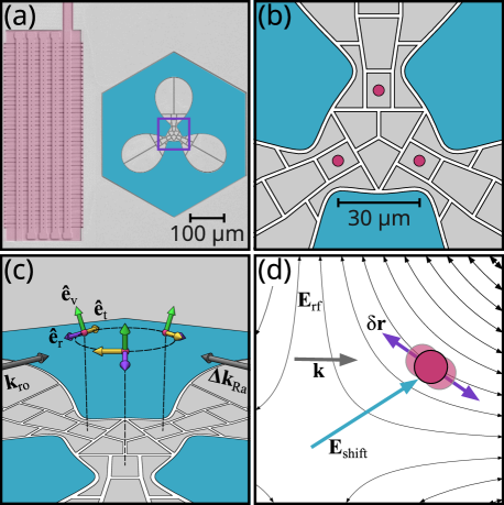
A static field lifts the energy degeneracy of hyperfine states in the electronic ground state manifold and defines a quantization axis. We optically pump to the state to prepare the internal state of the ions, and then couple to the other qubit state using microwave or stimulated Raman transitions [24]. The splitting between these states is . Other hyperfine transitions within the manifold can be driven with lasers or with microwave tones applied to the trap-integrated microwave antenna (see Fig. 1(a)). A laser beam at is used for Doppler cooling and state-dependent fluorescence readout [24] on the closed cycling transition. The beam is directed parallel to the electrode plane along the quantization axis ( shown in Fig. 1(c)), and has an elliptical cross-section with a 10:1 aspect ratio such that it illuminates the three ions nearly equally. Ion fluorescence is collected with an objective lens and imaged onto a camera or photomultiplier tube (PMT). Two counter-propagating beams (difference wave vector ) perpendicular to the cooling and detection beam are focused such that they illuminate only a single site. These beams are detuned blue from the transition and are used to drive stimulated Raman transitions.
Electric fields and curvatures in all three sites can be altered independently by applying suitable linear combinations of potentials to the 30 control electrodes. In this way it is possible to produce electric fields or curvatures of arbitrary spatial orientation in a certain site without altering the field or curvatures in the other two sites. These “shim” fields from the control electrodes can be used to compensate for stray fields so that the ion equilibrium position in each site is at the rf null. Likewise, stray curvatures can be compensated or mode frequencies and directions tuned in individual sites by other suitable linear combinations of applied potentials.
After compensation, excess micromotion can be induced by generating an additional field with the same electrodes to move an ion to a new equilibrium point given by Eq. (1). If the excess micromotion produced in this way has a component along the wave vector of a light field, the light will be modulated in the ion frame according to Eq. (Individual addressing and state readout of trapped ions utilizing rf micromotion). We use a gapless Biot-Savart type model [40] of the trap, combined with the experimentally measured secular frequencies at the rf nulls, to calculate , , , and given the voltages applied to each electrode. From Eqs. (1)-(4) we can then calculate and versus . For example, we calculate that the ion in the lower right site in Fig. 1(b) can be pushed along the radial mode direction by a field of magnitude . In the new equilibrium position , and the micromotion makes an angle of approximately 22.5 with the wave vector of the detection beam, yielding with a micromotion amplitude of nm.
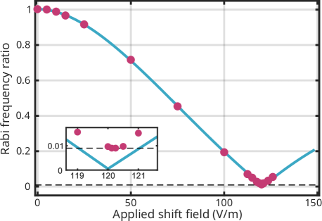
The limit of suppression is set by off-resonant scattering on the micromotion sidebands, as described in Eq.(1) in Ref. 36. For a narrow Raman transition where the Rabi rate for an unshifted ion , all micromotion sidebands are far off-resonant and the carrier coupling can be tuned almost to zero by induced micromotion. To show this experimentally we perform Doppler cooling and pulsed sideband cooling of all three modes of an ion in the leftmost site in Fig. 1(b) to near its ground state. We change by a certain amount and drive the Raman carrier transition for a variable duration. We then return to zero and detect the population in . We fit the resulting Rabi oscillations to find the Rabi frequency as a function of .
Fig. 2 plots the ratio as a function of the applied shift field, where is the Rabi rate at the rf null. The ratio reaches a sharp minimum of , or equivalently a carrier Rabi rate suppression factor of , at calculated values of and . The angle between and the rf electric field with calculated modulus is 15.3. As more shift field is applied, the component of the addressing field at the carrier frequency, and thus the coupling between the ion and Raman beams, increases again as anticipated.
We compare these results with theoretical predictions based on the calculated micromotion amplitude and direction at the shifted ion position. The resulting curve, with no free parameters, is shown in blue in Fig. 2 and agrees well with the measured data. We attribute the discrepancy between theory and experiment at the highest Rabi rate suppression to small fluctuations in the rf and static voltages applied to the trap electrodes.
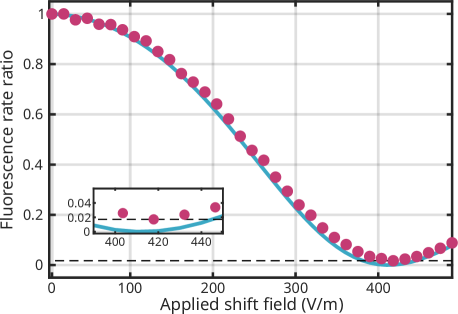
Resonant scattering, such as on a cycling transition in fluorescence readout, can also be suppressed by inducing micromotion [31, 36]. The relatively broader linewidth of this transition compared to limits the ratio of the minimum scattering rate to the maximum scattering rate to [36]. To demonstrate fluorescence suppression experimentally, we Doppler cool the ion and optically pump it into . We then apply and illuminate the ion with resonant light on the cycling transition. With no shifting field applied we detect an average of 10.7 counts on the PMT within . The ratio of count rate with an applied shifting field to the field-free count rate is shown in Fig. 3.
The normalized fluorescence rate ratio as a function of shift field is in close agreement with the theoretical model based on the carrier scattering rate (proportional to [30]) with effects due to saturation of the cycling transition included. Besides the limit imposed by off-resonant scattering on the micromotion sidebands, the observed minimal ratio is affected by the detector dark counts, stray detection light, and the degree of saturation of the transition with no shift applied. Still, the minimal scattering rate of the ion is nearly indistinguishable from that of an ion that does not participate in a cycling transition, or from the case of no ion in the trap.
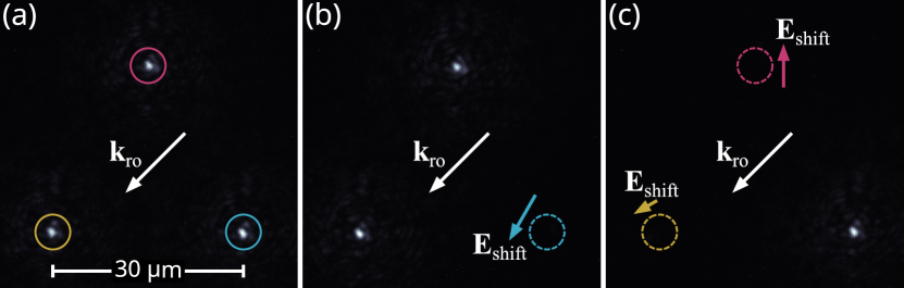
Individual readout of multiple ions is possible without individual optical addressing if shifting fields can be selectively applied to any subset of ions. We experimentally demonstrate this by trapping one ion in each of the three sites, preparing all ions in , and illuminating them nearly uniformly with the elliptical beam that resonantly drives the cycling transition.
After minimizing excess micromotion, all three ions are nearly uniformly bright in an electron-multiplying charge-coupled device (EMCCD) camera image with a exposure, shown in Fig. 4(a). By displacing one of the ions to where it minimally scatters, it can be verified that the combinations of potentials used in each case have negligible effect on the scattering rate of the ions in the two other sites (Fig. 4(b)). Individual readout requires displacing two ions at the same time, as shown in Fig. 4(c). We independently verified that the count histograms with two displaced and one bright ion are consistent with the histogram of a single bright ion trapped in any of the three sites. When all three ions are displaced simultaneously, an independently measured histogram is nearly indistinguishable from one taken with all three ions prepared in the dark state and “shelved” to the state with microwave pulses. These results certify that this technique is suitable for individual readout of three ions in this trap with no substantial loss in fidelity.
In summary, we have demonstrated the use of well-controlled shift fields to induce excess micromotion, thus selectively tuning the coupling of ions to incident light fields without modulating the driving fields themselves. We tune a Rabi frequency over two orders of magnitude, currently limited by small fluctuations of the static and rf potentials of the trap. We have also demonstrated readout of a single ion in an array by selectively suppressing the scattering of resonant readout light by neighboring ions. The demonstrated individual addressing techniques compare well with other recent results in multi-site traps [36, 41]. Similar addressing and readout of several ions should be achievable in any trap that has a sufficient number of electrodes to individually displace the ions [31]. The technique is particularly suited for 2-D arrays of ions illuminated from the side, where individual addressing with tightly-focused beams may be prohibitively difficult, especially as the array size grows. Independent, locally tunable coupling to global laser beams driving quantum gates could enable selectively parallelized operations across the array, further reducing overhead. Micromotion addressing can also be used in conjunction with other techniques to couple to specific ions in arrays, such as integrated optical waveguides [42, 43, 44, 41].
Acknowledgements.
The authors are grateful for the long-standing collaboration with Sandia National Laboratories on developing and fabricating the ion trap used in this work. We thank Adam Brandt and Ingrid Zimmermann for helpful comments on the manuscript. N.K.L. and J.F.N. are associates in the Professional Research Experience Program (PREP) operated jointly by NIST and the University of Colorado. This work was supported by the NIST Quantum Information Program.References
- Ludlow et al. [2015] A. D. Ludlow, M. M. Boyd, J. Ye, E. Peik, and P. O. Schmidt, Rev. Mod. Phys. 87, 637 (2015).
- Huntemann et al. [2016] N. Huntemann, C. Sanner, B. Lipphardt, C. Tamm, and E. Peik, Phys. Rev. Lett. 116, 063001 (2016).
- Brewer et al. [2019] S. M. Brewer, J.-S. Chen, A. M. Hankin, E. R. Clements, C. W. Chou, D. J. Wineland, D. B. Hume, and D. R. Leibrandt, Phys. Rev. Lett. 123, 033201 (2019).
- Burt et al. [2021] E. A. Burt, J. D. Prestage, R. L. Tjoelker, D. G. Enzer, D. Kuang, D. W. Murphy, D. E. Robison, J. M. Seubert, R. T. Wang, and T. A. Ely, Nature 595, 43 (2021).
- Blatt and Roos [2012] R. Blatt and C. F. Roos, Nat. Phys. 8, 277 (2012).
- Hempel et al. [2018] C. Hempel, C. Maier, J. Romero, J. McClean, T. Monz, H. Shen, P. Jurcevic, B. P. Lanyon, P. Love, R. Babbush, A. Aspuru-Guzik, R. Blatt, and C. F. Roos, Phys. Rev. X 8, 031022 (2018).
- Monroe et al. [2021] C. Monroe, W. C. Campbell, L.-M. Duan, Z.-X. Gong, A. V. Gorshkov, P. W. Hess, R. Islam, K. Kim, N. M. Linke, G. Pagano, P. Richerme, C. Senko, and N. Y. Yao, Rev. Mod. Phys. 93, 025001 (2021).
- Shapira et al. [2023] Y. Shapira, T. Manovitz, N. Akerman, A. Stern, and R. Ozeri, Phys. Rev. X 13, 021021 (2023).
- Blatt and Wineland [2008] R. Blatt and D. Wineland, Nature 453, 1008 (2008).
- Bruzewicz et al. [2019] C. D. Bruzewicz, J. Chiaverini, R. McConnell, and J. M. Sage, Appl. Phys. Rev. 6, 021314 (2019).
- Erhard et al. [2021] A. Erhard, H. Poulsen Nautrup, M. Meth, L. Postler, R. Stricker, M. Stadler, V. Negnevitsky, M. Ringbauer, P. Schindler, H. J. Briegel, R. Blatt, N. Friis, and T. Monz, Nature 589, 220 (2021).
- Egan et al. [2021] L. Egan, D. M. Debroy, C. Noel, A. Risinger, D. Zhu, D. Biswas, M. Newman, M. Li, K. R. Brown, M. Cetina, and C. Monroe, Nature 598, 281 (2021).
- Ryan-Anderson et al. [2022] C. Ryan-Anderson, N. C. Brown, M. S. Allman, B. Arkin, G. Asa-Attuah, C. Baldwin, J. Berg, J. G. Bohnet, S. Braxton, N. Burdick, J. P. Campora, A. Chernoguzov, J. Esposito, B. Evans, D. Francois, J. P. Gaebler, T. M. Gatterman, J. Gerber, K. Gilmore, D. Gresh, A. Hall, A. Hankin, J. Hostetter, D. Lucchetti, K. Mayer, J. Myers, B. Neyenhuis, J. Santiago, J. Sedlacek, T. Skripka, A. Slattery, R. P. Stutz, J. Tait, R. Tobey, G. Vittorini, J. Walker, and D. Hayes, arXiv:2208.01863 [quant-ph] (2022).
- Postler et al. [2022] L. Postler, S. Heuen, I. Pogorelov, M. Rispler, T. Feldker, M. Meth, C. D. Marciniak, R. Stricker, M. Ringbauer, R. Blatt, P. Schindler, M. Müller, and T. Monz, Nature 605, 675 (2022).
- Godun et al. [2014] R. M. Godun, P. B. R. Nisbet-Jones, J. M. Jones, S. A. King, L. A. M. Johnson, H. S. Margolis, K. Szymaniec, S. N. Lea, K. Bongs, and P. Gill, Phys. Rev. Lett. 113, 210801 (2014).
- Huntemann et al. [2014] N. Huntemann, B. Lipphardt, C. Tamm, V. Gerginov, S. Weyers, and E. Peik, Phys. Rev. Lett. 113, 210802 (2014).
- Pruttivarasin et al. [2015] T. Pruttivarasin, M. Ramm, S. G. Porsev, I. I. Tupitsyn, M. S. Safronova, M. A. Hohensee, and H. Häffner, Nature 517, 592 (2015).
- Dreissen et al. [2022] L. S. Dreissen, C.-H. Yeh, H. A. Fürst, K. C. Grensemann, and T. E. Mehlstäubler, Nat. Comm. 13, 7314 (2022).
- Kozlov et al. [2018] M. G. Kozlov, M. S. Safronova, J. R. Crespo López-Urrutia, and P. O. Schmidt, Rev. Mod. Phys. 90, 045005 (2018).
- Arrowsmith-Kron et al. [2023] G. Arrowsmith-Kron, M. Athanasakis-Kaklamanakis, M. Au, J. Ballof, R. Berger, A. Borschevsky, A. A. Breier, F. Buchinger, D. Budker, L. Caldwell, C. Charles, N. Dattani, R. P. de Groote, D. DeMille, T. Dickel, J. Dobaczewski, C. E. Düllmann, E. Eliav, J. Engel, M. Fan, V. Flambaum, K. T. Flanagan, A. Gaiser, R. G. Ruiz, K. Gaul, T. F. Giesen, J. Ginges, A. Gottberg, G. Gwinner, R. Heinke, S. Hoekstra, J. D. Holt, N. R. Hutzler, A. Jayich, J. Karthein, K. G. Leach, K. Madison, S. Malbrunot-Ettenauer, T. Miyagi, I. D. Moore, S. Moroch, P. Navrátil, W. Nazarewicz, G. Neyens, E. Norrgard, N. Nusgart, L. F. Pašteka, A. N. Petrov, W. Plass, R. A. Ready, M. P. Reiter, M. Reponen, S. Rothe, M. Safronova, C. Scheidenberger, A. Shindler, J. T. Singh, L. V. Skripnikov, A. V. Titov, S.-M. Udrescu, S. G. Wilkins, and X. Yang, arXiv:2302.02165 [nucl-ex] (2023).
- Wang et al. [2020] Y. Wang, S. Crain, C. Fang, B. Zhang, S. Huang, Q. Liang, P. H. Leung, K. R. Brown, and J. Kim, Phys. Rev. Lett. 125, 150505 (2020).
- Kranzl et al. [2022] F. Kranzl, M. K. Joshi, C. Maier, T. Brydges, J. Franke, R. Blatt, and C. F. Roos, Phys. Rev. A 105, 052426 (2022).
- Joshi et al. [2022] M. K. Joshi, F. Kranzl, A. Schuckert, I. Lovas, C. Maier, R. Blatt, M. Knap, and C. F. Roos, Science 376, 720 (2022).
- Wineland et al. [1998] D. Wineland, C. Monroe, W. Itano, D. Leibfried, B. King, and D. Meekhof, J. Res. Natl. Inst. Stan. 103, 259 (1998).
- Kielpinski et al. [2002] D. Kielpinski, C. R. Monroe, and D. J. Wineland, Nature 417, 709 (2002).
- Wan et al. [2019] Y. Wan, D. Kienzler, S. D. Erickson, K. H. Mayer, T. R. Tan, J. J. Wu, H. M. Vasconcelos, S. Glancy, E. Knill, D. J. Wineland, A. C. Wilson, and D. Leibfried, Science 364, 875 (2019).
- Pino et al. [2021] J. M. Pino, J. M. Dreiling, C. Figgatt, J. P. Gaebler, S. A. Moses, M. S. Allman, C. H. Baldwin, M. Foss-Feig, D. Hayes, K. Mayer, C. Ryan-Anderson, and B. Neyenhuis, Nature 592, 209 (2021).
- Moses et al. [2023] S. A. Moses, C. H. Baldwin, M. S. Allman, R. Ancona, L. Ascarrunz, C. Barnes, J. Bartolotta, B. Bjork, P. Blanchard, M. Bohn, J. G. Bohnet, N. C. Brown, N. Q. Burdick, W. C. Burton, S. L. Campbell, J. P. Campora, C. Carron, J. Chambers, J. W. Chan, Y. H. Chen, A. Chernoguzov, E. Chertkov, J. Colina, J. P. Curtis, R. Daniel, M. DeCross, D. Deen, C. Delaney, J. M. Dreiling, C. T. Ertsgaard, J. Esposito, B. Estey, M. Fabrikant, C. Figgatt, C. Foltz, M. Foss-Feig, D. Francois, J. P. Gaebler, T. M. Gatterman, C. N. Gilbreth, J. Giles, E. Glynn, A. Hall, A. M. Hankin, A. Hansen, D. Hayes, B. Higashi, I. M. Hoffman, B. Horning, J. J. Hout, R. Jacobs, J. Johansen, L. Jones, J. Karcz, T. Klein, P. Lauria, P. Lee, D. Liefer, S. T. Lu, D. Lucchetti, C. Lytle, A. Malm, M. Matheny, B. Mathewson, K. Mayer, D. B. Miller, M. Mills, B. Neyenhuis, L. Nugent, S. Olson, J. Parks, G. N. Price, Z. Price, M. Pugh, A. Ransford, A. P. Reed, C. Roman, M. Rowe, C. Ryan-Anderson, S. Sanders, J. Sedlacek, P. Shevchuk, P. Siegfried, T. Skripka, B. Spaun, R. T. Sprenkle, R. P. Stutz, M. Swallows, R. I. Tobey, A. Tran, T. Tran, E. Vogt, C. Volin, J. Walker, A. M. Zolot, and J. M. Pino, Phys. Rev. X 13, 041052 (2023).
- Kiesenhofer et al. [2023] D. Kiesenhofer, H. Hainzer, A. Zhdanov, P. C. Holz, M. Bock, T. Ollikainen, and C. F. Roos, PRX Quantum 4, 020317 (2023).
- Berkeland et al. [1998] D. J. Berkeland, J. D. Miller, J. C. Bergquist, W. M. Itano, and D. J. Wineland, J. App. Phys. 83, 5025 (1998).
- Leibfried [1999] D. Leibfried, Phys. Rev. A 60, R3335 (1999).
- Keller et al. [2015] J. Keller, H. L. Partner, T. Burgermeister, and T. E. Mehlstaeubler, J. App. Phys. 118, 104501 (2015).
- Nadlinger et al. [2021] D. P. Nadlinger, P. Drmota, D. Main, B. C. Nichol, G. Araneda, R. Srinivas, L. J. Stephenson, C. J. Ballance, and D. M. Lucas, arXiv:2107.00056 [quant-ph] (2021).
- Turchette et al. [1998] Q. A. Turchette, C. S. Wood, B. E. King, C. J. Myatt, D. Leibfried, W. M. Itano, C. Monroe, and D. J. Wineland, Phys. Rev. Lett. 81, 3631 (1998).
- Bermudez et al. [2017] A. Bermudez, P. Schindler, T. Monz, R. Blatt, and M. Müller, New J. Phys. 19, 113038 (2017).
- Gaebler et al. [2021] J. P. Gaebler, C. H. Baldwin, S. A. Moses, J. M. Dreiling, C. Figgatt, M. Foss-Feig, D. Hayes, and J. M. Pino, Phys. Rev. A 104, 062440 (2021).
- Wineland and Itano [1979] D. J. Wineland and W. M. Itano, Phys. Rev. A 20, 1521 (1979).
- Dehmelt [1968] H. G. Dehmelt, in Advances in Atomic and Molecular Physics, Vol. 3, edited by D. R. Bates and I. Estermann (Academic Press, 1968) pp. 53–72.
- Douglas et al. [2015] D. J. Douglas, A. S. Berdnikov, and N. V. Konenkov, Int. J. Mass Spectrom. 377, 345 (2015).
- Wesenberg [2008] J. H. Wesenberg, Phys. Rev. A 78, 063410 (2008).
- Kwon et al. [2023] J. Kwon, W. J. Setzer, M. Gehl, N. Karl, J. V. D. Wall, R. Law, D. Stick, and H. J. McGuinness, arXiv:2308.14918 [quant-ph] (2023).
- Mehta et al. [2016] K. K. Mehta, C. D. Bruzewicz, R. McConnell, R. J. Ram, J. M. Sage, and J. Chiaverini, Nat. Nano. 11, 1066 (2016).
- Mehta et al. [2020] K. K. Mehta, C. Zhang, M. Malinowski, T.-L. Nguyen, M. Stadler, and J. P. Home, Nature 586, 533 (2020).
- Niffenegger et al. [2020] R. J. Niffenegger, J. Stuart, C. Sorace-Agaskar, D. Kharas, S. Bramhavar, C. D. Bruzewicz, W. Loh, R. T. Maxson, R. McConnell, D. Reens, G. N. West, J. M. Sage, and J. Chiaverini, Nature 586, 538 (2020).