Breaking surface plasmon excitation constraint via surface spin waves
Abstract
Surface plasmons in two-dimensional (2D) electron systems have attracted great attention for their promising light-matter applications. However, the excitation of a surface plasmon, in particular, transverse-electric (TE) surface plasmon, remains an outstanding challenge due to the difficulty to conserve energy and momentum simultaneously in the normal 2D materials. Here we show that the TE surface plasmons ranging from gigahertz to terahertz regime can be effectively excited and manipulated in a hybrid dielectric, 2D material and magnet structure. The essential physics is that the surface spin wave supplements an additional freedom of surface plasmon excitation and thus greatly enhances the electric field in the 2D medium. Based on widely-used magnetic materials like yttrium iron garnet (YIG) and manganese difluoride (), we further show that the plasmon excitation manifests itself as a measurable dip in the reflection spectrum of the hybrid system while the dip position and the dip depth can be well controlled by the electric gating on the 2D layer and an external magnetic field. Our findings should bridge the fields of low-dimensional physics, plasmonics and spintronics and open a novel route to integrate plasmonic and spintronic devices.
Introduction.— Plasmons are collective excitations of electronic charge density in metallic structures. In three-dimensional (3D) systems, one has to overcome a gap of several electronvolts to excite the bulk plasma oscillations, which makes it challenging to be manipulated. The situation in two-dimensional (2D) systems is very different since the plasmon frequency is usually proportional to with being the propagating wavevector of plasmons [1], implying that the excitation energy can be desirably tuned far below the optical regime. Another benefit of the a 2D configuration is the electrical tunability of the Fermi energy and thus of the charge carrier density [2, 3]. As a result, surface plasmons in 2D materials, for example, graphene, have attracted significant attention with the well-developed fabrication technology of 2D materials [4, 5, 6, 2, 3, 7]. In particular, transverse magnetic (TM) plasmons are broadly studied while transverse electric (TE) plasmons are seldom studied for its restrictive excitation condition. For usual 2D systems with the parabolic electron dispersion, it is widely believed that the TE plasmons are not present for their positive imaginary component of conductivity, which is well described by the Drude model [8]. For graphene, it was theoretically proposed that the sign of the imaginary part of the conductivity may reverse near the spectral onset of intraband scattering to unlock the TE modes [9]. However, the resulting TE plasmons locating in infra and terahertz regime are yet to be verified.
On the other hand, spin waves – collective excitations of spins in ordered magnets – can carry information even in magnetic insulators, which largely reduces the Joule heating problem during information processing [10, 11]. Spintronic systems are also easily integrated with other physical systems, for example, photonic platforms, qubits and phonons, to form hybrid systems for multifunctional information processing [12, 13]. The frequency of spin waves ranges from gigahertz (GHz) in ferromagnets to terahertz (THz) in antiferromagnets [14]. This makes it possible to couple them to surface plasmons in 2D materials that have a continuous spectrum [15, 16, 17]. Hybrid 2D materials which include magnetic films, which attracted a lot of interest recently, [18, 19, 20, 21, 22] also provide an accessible platform to investigate the hybrid magnon-plasmon excitation.
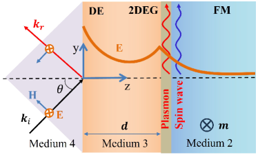
In this work, we show how the conventional constraint on a TE surface plasmon can be overcome by the interplay of surface plasmons and spin waves. In particular, we investigate the wave propagation in a hybrid dielectric (DE), 2D electron gas (2DEG) and magnetic insulator structure as shown in Fig. 1. An incident electromagnetic wave first induces a surface wave at the interface of media 4-3 and an evanescent wave inside medium 3. The evanescent wave propagates towards the 2DEG layer and excites a TE surface plasmon and surface spin waves simultaneously free from the constraint of 2DEG conductivity. The frequency of this surface plasmon-magnon polariton can be well tuned by an external magnetic field and falls into the GHz regime for ferromagnets (FM) and THz for antiferromagnets (AFM). For comparison, plasmons are barely generated when a magnet is replaced by a (non-magnetic) dielectric material. Furthermore, the excitation of the surface plasmon manifests as a sharp dip in the reflection spectrum of the layered structure. The depth and position of the dip are tunable by electric gating and by external magnetic field. These findings give a state-of-art demonstration of surface-plasmon excitations in hybrid 2D material-magnet structures and they should provide a feasible platform to study the interplay of magnon spintronics and plasmonics. The reported GHz and THz plasmons may find promising applications in designing novel plasmonic devices.
Physical model and the excitation spectrum.—Let us first look at the excitation spectrum of the hybrid system DE/2DEG/FM(DE) shown in Fig. 1, where the DE and FM layers are semi-infinite. The electromagnetic properties of the hybrid structure should satisfy the Maxwell’s equations
| (1) |
where and are respectively electric and magnetic fields, while and are respectively the electric displacement and the magnetic inductance with , and being the vacuum permittivity, vacuum permeability and material permittivity, respectively. After eliminating the electric components, Eqs. (1) can be combined to
| (2) |
where , with being the saturation magnetization and the normalized magnetization vector of the FM layer.
On the other hand, the magnetization dynamics in the FM layer is governed by the Landau-Lifshitz-Gilbert (LLG) equation [23, 24, 25]
| (3) |
The first and second terms on the right-hand side of Eq. (3) describe the precessional and damped motion of the magnetization toward the effective field with and being the gyromagnetic ratio and the Gilbert damping parameter, respectively. In general, is a sum of the external field , the dipolar field , the crystalline anisotropy field, and the exchange field. It is assumed that the external field is applied along the -axis and is strong enough to generate a uniform equilibrium state . Then the spin-wave excitation above this ground state can be represented as with and the dynamics of is derived by linearizing the LLG equation (3) around as
| (4) |
where , with , . Without loss of generality, we have neglected the exchange field, because it does not contribute significantly to the low-energy excitation of spin-waves in the soft magnets like yttrium iron garnet (YIG).
By substituting Eq. (4) into the Maxwell’s equations (2), we can derive self-contained equations of and . We consider an incident wave with momentum . Then the spins mainly oscillate in the and directions, and the combined LLG and Maxwell equations in medium 2 read
| (5) |
By solving Eqs (5), we derive the surface spin-wave mode with , and are related to each other by the determinantal equation. Unless stated otherwise, we always label the wavevector and decay exponent in medium by and , and they satisfy ().
In the dielectric medium 3, , the TE wave solution to the Maxwell’s equations reads with the relation . At the interface of media 3 and 2, the tangential components of electric field should be continuous while the tangential components of magnetic field are connected by the surface electric currents corresponding to surface plasmons excitations in the 2DEG layer, i.e.
| (6) |
where we shifted the plane to the interface of 2DEG for simplicity and imposed the requirement of in-plane momentum conservation . Nontrivial solutions of Eqs. (6) appear provided
| (7) |
where () depends on the nature of medium 2 such that
| (8a) | ||||
| (8b) | ||||
This is the first key result of our work. When medium 2 is a dielectric, the resonance condition is reduced to the familiar form in literature by inserting into Eq. (7) [9]. This condition only has real solutions when is purely imaginary and otherwise has a negative imaginary component. Therefore, it cannot be fulfilled for conventional 2DEG whose conductivity is well described by the Drude model [26, 9, 27] i.e. with , being the Fermi energy, and being the relaxation rate of carriers. This implies that the TE surface plasmons cannot be resonantly excited using the conventional Otto setup.
The situation changes dramatically when medium 2 is a ferromagnet. By plugging into Eq. (7), we find that the resonant frequency should satisfy the equation
| (9) |
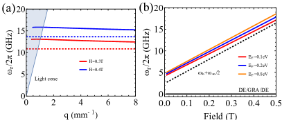
Firstly, we recover the frequency of surface magnon mode in the magnetostatic limit () when as (blue and red dashed lines in Fig. 2(a)) [29, 30]. As we go beyond this limit, the spectrum can be obtained by numerically solving Eq. (9), with the result shown in Fig. 2(a). Clearly, there is a crossing between the light cone and surface plasmon-magnon dispersion, suggesting the possibility to match both momentum and frequency between the incident photons and hybrid plasmon-magnon modes and thus enabling the plasmon excitations. It is noteworthy that the resonant frequency can be well tuned in the GHz regime by the external field, as shown in Fig. 2(b).
Reflection rate.–Now we proceed to demonstrate that the surface plasmons and magnons can be simultaneously excited by shining a proper wave on the hybrid system. The excited surface plasmon will carry away electromagnetic energy and reduce the reflection rate of the system, which provides a feasible way to detect the excitation of surface plasmons in our setup. Here we consider a -polarized incident wave with electric field perpendicular to the incident plane in medium 4, where and , as shown in Fig. 1. To satisfy the Maxwell’s equations, the magnetic and electric fields should read and with , where label the incident and reflected waves, respectively. The finite thickness of medium 3 allows for the coexistence of exponential increase and decay modes, i.e.
| (10) | ||||
where and .
Now the boundary conditions require the continuity of the tangential components of both electric and magnetic fields at interfaces of media 4-3 and 3-2, i.e.
| (11a) | |||
| (11b) | |||
| (11c) | |||
| (11d) | |||
By expressing all the magnetic fields by their electric fields counterparts and solving the resulting linear equations, we can derive the reflection coefficient as [31]
| (12) |
where . For very thin dielectric medium 3 (), the reflection coefficient is simplified as
| (13) |
This is the second key result of our work. Figure 3(a) shows the reflection rate as a function of the frequency of incident wave when with the critical angle (). A sharp dip in the reflection rate appears at the resonant frequency (vertical dashed line), implying a resonant excitation of the surface plasmon-magnon polariton. As a comparison, the reflection rate is approximately one when the magnetic layer is replaced by a normal dielectric with the same permittivity (blue line), indicating very weak plasmon excitations. This comparison explicitly confirms that the magnetic layer releases the constraint to excite the TE surface plasmon. To understand the essential physics, we further plot the electric field in the 2DEG layer as well as the spin-wave amplitude as a function of the wave frequency in Fig. 3(a). When medium 2 is a magnetic layer, the spin-wave is maximally excited at the resonant frequency, which also significantly enhances the electric field in the 2DEG layer and thus strongly excites the surface plasmon mode. However, there is no enhancement of electric fields when medium 2 is a dielectric. Now it seems safe to conclude that the surface spin waves boost the surface plasmon excitations, which carry away significant amount of electromagnetic energy and thus generate a considerable dip in the reflection spectrum.
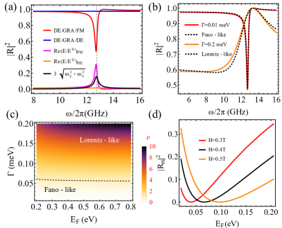
Lineshape of the reflection spectrum.— We further notice that the lineshape of the reflection spectrum near the resonance is asymmetric. Physically, this may be interpreted as an interference effect between the background continuum spectrum and a discrete mode. Here the continuous mode is the flat reflection spectrum without considering the magnetic properties of medium 2 (blue line in Fig. 3(a)) while the discrete mode is the hybrid surface plasmon-magnon mode. Specifically, we can expand the reflection rate (13) around the resonance frequency and derive that [31]
| (14) |
where is the well-known Fano parameter, is the modified resonance frequency, is the effective linewidth, and is the strength of the Lorentz contribution. In general, near the resonance position, we may characterize the relative weight of the Fano and Lorentz lineshapes by defining a lineshape index as [31]
| (15) |
When the relaxation rate of carriers in 2DEG is very small, the ratio is much smaller than one for higher Fermi energy, then the reflection spectrum is Fano-like [32], as shown in Fig. 3(b) (red line). When the relaxation rate is very high, the ratio becomes . In this regime, the Lorentz contribution can be comparable and even dominate the Fano contribution (orange line in Fig. 3(b)). The complete phase diagram of in the plane is shown in Fig. 3(c). It is noteworthy that the Fermi energy of the 2DEG can be tuned by electric gating [33], which makes it possible to tune the lineshape and thus the minimum reflection rate of the hybrid system. Figure 3(d) shows that the minimum reflection rate can reach zero if the Fermi energy and external fields are appropriately tuned. In this situation, all the incident wave energy is converted to excite surface plasmons.
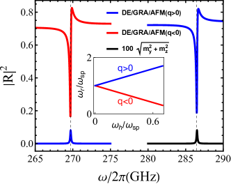
Extension to antiferromagnet.— The essential physics presented above can be extended to AFMs. As an example, we consider a two-sublattice AFM insulator with the easy axis and external field both aligned along the -axis. Following the theoretical approach presented above, we derive a similar form of reflection coefficient (13) with and replaced by their AFM counterparts [31]. Figure 4 shows the reflection rate as a function of the incident wave frequency. Unlike the ferromagnetic case, two distinguished dips appear in the sub-THz regime (red and blue lines) depending on the direction of in-plane momentum () of incident wave. This difference is because there are two surface spin-wave modes in an AFM propagating in directions respectively [36]. The incident wave with () only excites the surface spin wave and plasmon propagating in the () directions. Therefore one may generate nonreciprocal surface plasmons by properly choosing the wave frequency.
Discussions and conclusions.—In conclusion, we have shown that surface spin waves in both ferromagnet and antiferromagnet can boost the excitation of TE surface plasmons ranging from GHz to THz regime in 2D materials. The excitation condition does not require the purely negative imaginary conductivity and is thus applicable to a wide class of 2D systems. The excitation of surface plasmons carries away electromagnetic energy and generates a local minimum in the reflection spectrum of the system. The position of minimal reflection is tunable by both external magnetic field and electric gating on the 2D systems, providing an accessible way to probe the plasmon excitation in the experiments. Our findings should open a novel and feasible hybrid platform to study the surface plasmons and further promote its application in designing plasmonic devices down to GHz regime. In the future, it would be interesting to extend our formalism to the quantum regime to study the entanglement between magnons and plasmons and their potential applications in quantum information science.
Acknowledgments.— The work was supported by the Dutch Research Council (NWO). H.Y.Y acknowledges the helpful discussions with Mathias Kläui, Rembert Duine, Alexander Mook, Pieter Gunnink, Artem Bondarenko, Mikhail Cherkasskii and Zhaoju Yang.
References
- Zayats et al. [2005] A. V. Zayats, I. I. Smolyaninov, and A. A. Maradudin, Phys. Rep. 408, 131 (2005), ISSN 0370-1573, URL https://www.sciencedirect.com/science/article/pii/S0370157304004600.
- Rodin et al. [2020] A. Rodin, M. Trushin, A. Carvalho, and A. H. Castro Neto, Nat. Rev. Phys. 2, 524 (2020), ISSN 2522-5820, URL https://doi.org/10.1038/s42254-020-0214-4.
- Ukhtary and Saito [2020] M. S. Ukhtary and R. Saito, Carbon 167, 455 (2020), ISSN 0008-6223, URL https://www.sciencedirect.com/science/article/pii/S0008622320304607.
- Rodrigo et al. [2015] D. Rodrigo, O. Limaj, D. Janner, D. Etezadi, F. J. G. de Abajo, V. Pruneri, and H. Altug, Science 349, 165 (2015).
- Iranzo et al. [2018] D. A. Iranzo, S. Nanot, E. J. C. Dias, I. Epstein, C. Peng, D. K. Efetov, M. B. Lundeberg, R. Parret, J. Osmond, J.-Y. Hong, et al., Science 360, 291 (2018).
- Epstein et al. [2020] I. Epstein, D. Alcaraz, Z. Huang, V.-V. Pusapati, J.-P. Hugonin, A. Kumar, X. M. Deputy, T. Khodkov, T. G. Rappoport, J.-Y. Hong, et al., Science 368, 1219 (2020).
- Zhao et al. [2023] W. Zhao, S. Wang, S. Chen, Z. Zhang, K. Watanabe, T. Taniguchi, A. Zettl, and F. Wang, Nature 614, 688 (2023), ISSN 1476-4687, URL https://doi.org/10.1038/s41586-022-05619-8.
- Jablan et al. [2009] M. Jablan, H. Buljan, and M. Soljačić, Phys. Rev. B 80, 245435 (2009), URL https://link.aps.org/doi/10.1103/PhysRevB.80.245435.
- Mikhailov and Ziegler [2007] S. A. Mikhailov and K. Ziegler, Phys. Rev. Lett. 99, 016803 (2007), URL https://link.aps.org/doi/10.1103/PhysRevLett.99.016803.
- Chumak et al. [2015] A. V. Chumak, V. I. Vasyuchka, A. A. Serga, and B. Hillebrands, Nat. Phys. 11, 453 (2015), ISSN 1745-2481, URL https://doi.org/10.1038/nphys3347.
- Pirro et al. [2021] P. Pirro, V. I. Vasyuchka, A. A. Serga, and B. Hillebrands, Nat. Rev. Mater. 6, 1114 (2021), ISSN 2058-8437, URL https://doi.org/10.1038/s41578-021-00332-w.
- Yuan et al. [2022] H. Y. Yuan, Y. Cao, A. Kamra, R. A. Duine, and P. Yan, Phys. Rep. 965, 1 (2022), ISSN 0370-1573, URL https://www.sciencedirect.com/science/article/pii/S0370157322000977.
- Zare Rameshti et al. [2022] B. Zare Rameshti, S. Viola Kusminskiy, J. A. Haigh, K. Usami, D. Lachance-Quirion, Y. Nakamura, C.-M. Hu, H. X. Tang, G. E. Bauer, and Y. M. Blanter, Phys. Rep. 979, 1 (2022), ISSN 0370-1573, URL https://www.sciencedirect.com/science/article/pii/S0370157322002460.
- Baltz et al. [2018] V. Baltz, A. Manchon, M. Tsoi, T. Moriyama, T. Ono, and Y. Tserkovnyak, Rev. Mod. Phys. 90, 015005 (2018), URL https://link.aps.org/doi/10.1103/RevModPhys.90.015005.
- Dyrdał et al. [2023] A. Dyrdał, A. Qaiumzadeh, A. Brataas, and J. Barnaś, Phys. Rev. B 108, 045414 (2023), URL https://link.aps.org/doi/10.1103/PhysRevB.108.045414.
- Ghosh et al. [2023] S. Ghosh, G. Menichetti, M. I. Katsnelson, and M. Polini, Phys. Rev. B 107, 195302 (2023), URL https://link.aps.org/doi/10.1103/PhysRevB.107.195302.
- Costa et al. [2023] A. T. Costa, M. I. Vasilevskiy, J. Fernandez-Rossier, and N. M. R. Peres, Nano Lett. 23, 4510 (2023), ISSN 1530-6984, URL https://doi.org/10.1021/acs.nanolett.3c00907.
- Mendes et al. [2015] J. B. S. Mendes, O. Alves Santos, L. M. Meireles, R. G. Lacerda, L. H. Vilela-Leão, F. L. A. Machado, R. L. Rodríguez-Suárez, A. Azevedo, and S. M. Rezende, Phys. Rev. Lett. 115, 226601 (2015), URL https://link.aps.org/doi/10.1103/PhysRevLett.115.226601.
- Song et al. [2018] T. Song, X. Cai, M. W.-Y. Tu, X. Zhang, B. Huang, N. P. Wilson, K. L. Seyler, L. Zhu, T. Taniguchi, K. Watanabe, et al., Science 360 (2018), ISSN 0036-8075.
- Takiguchi et al. [2019] K. Takiguchi, L. D. Anh, T. Chiba, T. Koyama, D. Chiba, and M. Tanaka, Nat. Phys. 15, 1134 (2019), ISSN 1745-2481, URL https://doi.org/10.1038/s41567-019-0621-6.
- Ghiasi et al. [2021] T. S. Ghiasi, A. A. Kaverzin, A. H. Dismukes, D. K. de Wal, X. Roy, and B. J. van Wees, Nat. Nanotech. 16, 788 (2021), ISSN 1748-3395, URL https://doi.org/10.1038/s41565-021-00887-3.
- Hu et al. [2022] J. Hu, J. Luo, Y. Zheng, J. Chen, G. J. Omar, A. T. S. Wee, and A. Ariando, J. Alloys Compd. 911, 164830 (2022), ISSN 0925-8388, URL https://www.sciencedirect.com/science/article/pii/S092583882201221X.
- Landau [1965] L. D. Landau, in Collected Papers of L.D. Landau, edited by D. ter Haar (Pergamon, 1965), pp. 101–114, ISBN 978-0-08-010586-4, URL https://www.sciencedirect.com/science/article/pii/B9780080105864500237.
- Gilbert [2004] T. Gilbert, IEEE Trans. Magn. 40, 3443 (2004).
- Tserkovnyak et al. [2005] Y. Tserkovnyak, A. Brataas, G. E. W. Bauer, and B. I. Halperin, Rev. Mod. Phys. 77, 1375 (2005), URL https://link.aps.org/doi/10.1103/RevModPhys.77.1375.
- Jackson [1998] J. Jackson, Classical Electrodynamics (Wiley, 1998), ISBN 9780471309321, URL https://books.google.nl/books?id=FOBBEAAAQBAJ.
- Chang et al. [2016] Y.-C. Chang, C.-H. Liu, C.-H. Liu, S. Zhang, S. R. Marder, E. E. Narimanov, Z. Zhong, and T. B. Norris, Nat. Commun. 7, 10568 (2016), ISSN 2041-1723, URL https://doi.org/10.1038/ncomms10568.
- Kuznetsov et al. [2019] E. A. Kuznetsov, A. B. Rinkevich, and D. V. Perov, Tech. Phys. 64, 629 (2019), ISSN 1090-6525, URL https://doi.org/10.1134/S1063784219050128.
- Eshbach and Damon [1960] J. R. Eshbach and R. W. Damon, Phys. Rev. 118, 1208 (1960), URL https://link.aps.org/doi/10.1103/PhysRev.118.1208.
- Serga et al. [2010] A. A. Serga, A. V. Chumak, and B. Hillebrands, J. Phys. D: Appl. Phys. 43, 264002 (2010), URL https://dx.doi.org/10.1088/0022-3727/43/26/264002.
- [31] See the Supplementary Material for the detailed derivation of the reflection rate and spin-wave amplitude in the ferromagnetic case, the reflection spectrum as a superposition of Fano and Lorentz shape together with an analytical form of the lineshape paramters and the reflection spectrum in the antiferromagnetic case.
- Fano [1961] U. Fano, Phys. Rev. 124, 1866 (1961), URL https://link.aps.org/doi/10.1103/PhysRev.124.1866.
- Craciun et al. [2011] M. Craciun, S. Russo, M. Yamamoto, and S. Tarucha, Nano Today 6, 42 (2011), ISSN 1748-0132, URL https://www.sciencedirect.com/science/article/pii/S1748013210001623.
- Johnson and Nethercot [1959] F. M. Johnson and A. H. Nethercot, Phys. Rev. 114, 705 (1959), URL https://link.aps.org/doi/10.1103/PhysRev.114.705.
- Seehra and Helmick [1984] M. S. Seehra and R. E. Helmick, J. Appl. Phys. 55, 2330 (1984), ISSN 0021-8979, URL https://doi.org/10.1063/1.333652.
- Camley [1980] R. E. Camley, Phys. Rev. Lett. 45, 283 (1980), URL https://link.aps.org/doi/10.1103/PhysRevLett.45.283.