Lightweight Masking Against
Static Power Side-Channel Attacks
Abstract
This paper presents a novel defense strategy against static power side-channel attacks (PSCAs), a critical threat to cryptographic security. Our method is based on (1) carefully tuning high-Vth versus low-Vth cell selection during synthesis, accounting for both security and timing impact, and (2), at runtime, randomly switching the operation between these cells. This approach serves to significantly obscure static power patterns, which are at the heart of static PSCAs. Our experimental results on a commercial 28nm node show a drastic increase in the effort required for a successful attack, namely up to 96 times more traces. When compared to prior countermeasures, ours incurs little cost, making it a lightweight defense.
Index Terms:
Power Side-Channel, MaskingI Introduction
With the rapid expansion of technological capabilities aimed at addressing increasing demands, we witness the emergence of sub-nanometer transistors. While this innovation plays a crucial role in tackling the need for fast integrated circuits (ICs), it concurrently introduces a set of challenges that necessitate careful consideration from a design perspective. Notably, these advancements escalate security vulnerabilities, as potential attackers can now access more substantial information leakage than what was possible with older technologies.
More specifically, to facilitate quicker transitions, there is a requirement to lower the threshold voltage (Vt). Within any commercial library, one can observe a spectrum of cells characterized by diverse Vt properties. These range from fast-acting cells to low-power variants, the latter being particularly crucial for devices reliant on battery power. An example is shown in Table I for a D flip-flop (D-FF) across three different cell types, namely LVT (low Vt), RVT (regular Vt), and HVT (high Vt), respectively. There is a few magnitudes increase in leakage power as one transitions from HVT cells to LVT cells.
From a designer’s standpoint, the objective is to limit the utilization of LVT cells as much as possible, aiming to curtail power consumption. Still, due to timing failures in certain pathways, the use of these high-speed cells becomes an unavoidable necessity in specific contexts, timing closure in particular. If such modifications are done in traditional CAD flows, i.e., without security in mind, the implications for the resilience of the circuits can be negative [1, 2]. At the same time, as we show in this work, a careful and security-aware tuning of LVT cells usage can enable an competitive yet lightweight defense mechanism.
Side-channel attacks present a significant threat to security, especially as they have proven to be effective against cryptographic algorithms, compromising their security assurances due to hardware limitations. A variety of side channels, including power, timing, and electromagnetic, have been explored extensively [3, 4, 5], revealing their potential to leak confidential information. Among these, the power side-channel has been the focus of most attacks [6], particularly for the dynamic power side-channel (D-PSC). This is because dynamic power contributes the significant share of total power, especially for older technologies. For modern and smaller technology nodes, however, especially with the use of low Vt cells, leakage power effects become significant and noticeable. Thus, static power side-channel (S-PSC) attacks become more promising as well. Our contributions are threefold:
-
1.
Design a lightweight masking against S-PSC attacks.
-
2.
Use of different Vt and drive strengths as a defense.
-
3.
Mixing strategies yielding a low-overhead, resilient implementation.
| CLK | D | Q | Leakage Current [Norm.] | ||
| LVT | RVT | HVT | |||
| 0 | 0 | 0 | 112.8 | 9.0 | 1 |
| 0 | 0 | 1 | 136.0 | 10.1 | 1 |
| 0 | 1 | 0 | 129.3 | 10.1 | 1 |
| 0 | 1 | 1 | 118.3 | 9.2 | 1 |
| 1 | 0 | 0 | 138.1 | 10.2 | 1 |
| 1 | 0 | 1 | 125.0 | 9.1 | 1 |
| 1 | 1 | 0 | 131.5 | 9.7 | 1 |
| 1 | 1 | 1 | 93.5 | 7.1 | 1 |
II Background and Motivation
Power side-channel attacks (PSCA) measure the power consumption of a device to extract sensitive data like secret keys in cryptographic chips. There are two variants of the threat model: with or without controlling the input texts. We adopt the more stringent latter variant. We assume the attacker has control over the clock, which is common for PSCAs. Prominent options for PSCAs include differential power analysis (DPA) [5], and correlation power analysis (CPA) [7, 8]. DPA compares power consumed by similar operations to retrieve the secret key, whereas CPA uses the Pearson correlation coefficient to correlate the actual and predicted power profiles to infer the secret key. We employ CPA.
PSCAs can be conducted as attacks on dynamic (D-PSCAs) or static power (S-PSCAs). A D-PSCA extracts secret data by observing and interpreting power use while a device is active, whereas a S-PSCA does so when the device is idle. Note that data-related power patterns are strongly expressed even in the absence of active data processing (Table I). While D-PSCAs require accurate timing, S-PSCAs work with halted clocks, rendering this attack easier to conduct in the real world.
Prior work has used masking to hide the unique power profiles of circuits during sensitive computations. While prior work on D-PSC has shown effectiveness of masking techniques, masking incurs overhead where the final design can be multiple times larger than the original. This makes it impractical in the real-world where cost per mm2 of silicon is high. Further, most of the masking-based protection is tailored against D-PSCAs. There is a subtle difference when it comes to masking that aims to thwart the S-PSC information leakage: irrespective of the additional circuitry used for masking, the parts that store the actual data can still leak information [9, 10, 11]. In other words, regular masking schemes devised against D-PSCAs do not directly apply against S-PSCAs.
III Related Work
The work in [12] unveiled the S-PSC’s potential as a security vulnerability. Practical experimentation with S-PSCAs utilizing FPGAs was later undertaken in [2], marking one of the initial research in this domain. The significant impact of leakage power on PSC, particularly in advanced technology nodes, was underscored in [1]. In a similar direction, [13] provided an experimental analysis of how various measurement factors influence the success rate of S-PSCAs. The work of [14] highlighted the increasing effects of aging on smaller technology nodes, thus escalating the security risks of contemporary devices when subjected to S-PSCAs. A comprehensive multivariate analysis focusing on S-PSC was presented in [10], while [15] delved into both static and dynamic PSC in the context of the 65nm technology node, demonstrating the vulnerability of even older nodes to S-PSCAs. The work in [9] studied the role of Vt cells on the S-PSC from the perspective of hardware Trojan attacks.
[16] provided a thorough evaluation of countermeasures against S-PSCAs, including logic balancing, although noting the substantial overheads associated with the techniques. Their analysis, conducted on a 28nm IC, highlighted the critical role of different Vt cells in this context. [17] introduced standard-cell delay-based dual-rail pre-charge logic (SC-DDPL) as a countermeasure against S-PSC. The scheme uses NAND gates to enhance design symmetry and power profile uniformity. This method is incompatible with commercial CAD tool optimization flows, a notable limitation. Another masking defense [18] incurs additional overheads.
IV Methodology
Our work is based on the observation that the type of Vt cells substantially impacts the S-PSC, with orders of magnitudes shown in Table I.
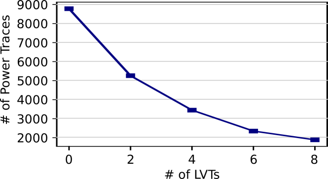
For common crypto cores like AES, state registers which hold the intermediate cipher values after each round are the most vulnerable among all the FFs [9, 16]. Thus, we initially explore the role of Vt cell selection for the state registers for an AES crypto core under S-PSCA (Figure 1). Note that all setup details are provided in Sec. V-A.
From Figure 1, we note two key observations. First, the role of LVT cells (versus HVT and RVT cells) is significant. The more LVT cells are used for the sensitive state registers, the less effort is required for a successful S-PSCA. Note here that the assignment of LVT cells to state registers is randomized, to avoid any bias for such circuit-level details, and the results are averaged across multiple runs. Second, the S-PSC resilience is relatively weak as less than 10K traces are sufficient.
IV-A Proposed Defense Against S-PSCA
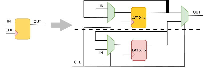
Instead of directly linking sensitive data into state registers, we propose an extended circuit primitive for those registers as illustrated in Figure 2, where the original FF (left) is transformed into a circuit primitive (right). The randomized changes in power patterns introduced by our scheme hide/mask the actual power consumption, making it harder for attackers to understand or predict them using their usual methods.
More specifically, a regular state register is extended into an entangled implementation of LVT FFs of different driver strengths. Note the following for the primitive’s working and the resulting resilience against S-PSCAs.
First, the primitive could be tailored for any number of paths with different driver-strength LVT FFs. In this work, we consider only 1 or 2 paths, as also indicated by the dashed line in the figure. These options already increase the resilience of the cipher core significantly (Sec. V).
Second, we utilize LVT FFs first and foremost for the fact that their static power is significantly larger and more varied for different data conditions than RVT and HVT cells (Table I). We also utilize LVT FFs for their fast switching behaviour: given that the primitive incorporates additional components, the timing delay on the paths covered by these primitives increases, but with the use of LVT FFs this impact is limited. Thus, timing closure becomes easier again.
Third, for the default configuration of the primitive shown in Figure 2, upon selection of ‘0’ for the control signal (CTL), the primitive operates on the upper path with an LVT FF of strength a. Conversely, selecting ‘1’ activates the lower path with an LVT FF of strength b. It is important to understand that both paths produce functionally equivalent outputs; there is no disruption of any of the regular cipher operations whatsoever. Rather, these paths are masked variants of each other, distinguished only by their Vt cells and driver strengths and their different impact on leakage power.
Finally, and most important for security, the randomized switching between the different paths introduces a layer of unpredictability into the S-PSC patterns as follows. Note the data feedback loops from the FFs’ outputs back to their inputs, which are only active whenever the corresponding path itself is not active. Thus, the path that is not active at any given cycle will express data-dependent S-PSC information leakage based on the previous cycle which may or may not align with the data in the current cycle.111Here it is important to note that, while S-PSCAs do not require the IC to be running during the actual power measurement, an attacker would still need to activate the clock intermittently, namely to allow for the different rounds of AES to be processed in particular and for different cipher messages to be processed in general, all to gather power traces for different (static) data hold in the sensitive FFs. Naturally, the toggling of the clock signal could be utilized – in a randomized manner – for the CTL signal. Furthermore, following the exploratory study shown in Figure 1, the application of the circuit primitive should be tuned carefully. As we find during our experiments (Sec. V), it is not about limiting/reducing the number of primitives in general (as one might guess from Figure 1 where more LVT cells lead to lower resilience) but rather about a wide range for LVT versus RVT/HVT cells across the different bytes of the state registers.
In short, there are two-fold noise patterns arising for the S-PSC thanks to our proposed defense: 1) for the system-level S-PSC – which is also the one encountered by real-world attackers – the varying instantiation of the primitive across bytes incurs considerable diverse power patterns (due to LVT cells in the primitive versus RVT/HVT cells in regular FFs); 2) for the byte-level S-PSC – which naturally contributes to the system-level S-PSC – the randomized feeding of current-cycle versus previous-cycle data to the different-driver strength FFs.
Due to the obfuscation of power traces by these noise patterns, a substantially greater number of samples would be required to perform a successful S-PSCA, drastically increasing the complexity and effort needed for any such attempt. This augmentation in security is shown in Sec. V, where we provide a comprehensive analysis.
IV-B Implementation Details
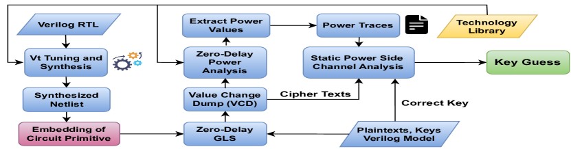
Figure 3 outlines the workflow for our scheme.
IV-B1 Design Implementation
Initially, RTL of the crypto core (AES in this work) is synthesized using the chosen technology libraries, taking into account all available Vt cell types. Next, the proposed masking circuitry is embedded as in replacing all instances of state registers. Next, the netlist’s functionality, post-synthesis, is confirmed by running the testbench. The testbench has a series of plain-texts alongside a key or multiple keys. Subsequently, the testbench generates the cipher-texts which are then validated against a golden software implementation of the crypto core.
IV-B2 Simulation-Based Power Analysis
Through the course of the gate-level simulations conducted for verification, a value change dump (VCD) file is produced as well. This format is essential to capture the data patterns across all gates/nodes in the netlist at a user-defined temporal resolution, such as ps. Next, this VCD file, along with the post-synthesis netlist and the selected libraries, is utilized for power simulation.
The power simulation tool assesses the power consumed by each cell, incorporating 1) static/leakage power, 2) internal power (from input-pin switching), and 3) switching power (resulting from output-pin switching). The library’s power characterization provides the necessary data for leakage and internal power of the cells, and the power simulation tool uses VCD’s state information for input/output data to calculate the design’s power consumption. In this work, the focus is on static power; the above description stems from a default power simulation setup which follows best practices from industry.
Rather than employing full-timing simulations, zero-delay simulations are used, as the focus is on capturing the static power for specific clock cycles, not on determining the average leakage power. This static power value is constant, whether it is derived from a full-timing simulation based on standard delay format (SDF) information or from a zero-delay simulation. Also, power traces are obtained sequentially while processing different texts for the specified secret key(s), with a focus on the operations in the final round, as outlined in [8].
IV-B3 Sampling-Based CPA Attack
In general, CPA employs the Pearson correlation coefficient (PCC) to ascertain the link between the power consumed during cryptographic operations and the confidential data [8]. It involves comparing the actual power usage with anticipated power consumption patterns for various potential key values across numerous observations. Subsequently, the key is deduced byte by byte from the candidates that exhibit the highest PCC values.
Anticipated power consumption patterns are derived based on a selected power model [8]. In the context of S-PSCA, one opts for either the Hamming weight (HW) of the cipher-texts or the Hamming distance (HD) between the cipher-texts and the preceding final-round operation. The choice depends on the power consumption characteristics of the technology nodes in question. Real-world attackers explore both options.
We embed CPA into a sampling framework, to provide more robust insights than single trial-and-error attack runs often conducted in prior art. On a high-level, the sampling framework iteratively supplies an increasing number of traces to the CPA and tracks the success rate across multiple trials for CPA runs. That is, given a large set of traces, we start with smaller subsets, whereas many different, randomly selected permutations of subsets are considered for each number of traces to explore in detail. The process halts once a specific confidence level is achieved for the current number of traces available to the CPA, such as a 90% success rate.
For computational efficiency, we implement large-scale multi-threading and orchestrate the sampling process as follows. First, we do coarse sampling, which involves fewer randomly selected permutations per step and a larger step size (i.e., larger number of traces) to quickly pinpoint a reasonable starting point. From that starting point, we conduct detailed sampling with more trials and using a smaller step size.
V Experiments
V-A Setup
We conduct all experiments, including the preliminary analysis presented in Sec. IV, on an AMD EPYC 7542 server with Red Hat Enterprise Linux Server Release 7.9. In terms of the CAD flow for our implementation, we utilize various commercial tools. For both RTL and gate-level functional simulations, we employ Synopsys VCS M-2017.03-SP1. Logic synthesis is carried out using Synopsys DC M-2016.12-SP2, while power simulations are performed with Synopsys PrimeTime PX M-2017.06. The sampling-based CPA framework is implemented upon the open-source code in [7].
We employ a commercial library for the 28nm node. We consider the TT corners which are characterized for 25 degrees Celsius and 0.9V. The timing constraint is 0.5n. Standard optimization techniques are applied during the synthesis process, which implies that LVT cells are used sparingly in the baseline designs. In fact, none of the state registers were implemented using LVT cells by default. After integration of the proposed circuit primitive, we apply ECO fixes for timing closure as needed, while making sure that the primitive instances themselves are not revised/optimized. The overheads resulting from ECO fixing are included in cost reports.
For the AES design, we leverage a regular RTL that is working on 128-bit keys and 128-bit texts, uses look-up tables for the S-Box, and has no other PSC countermeasure in place.
For all CPA runs, we consider 1M traces in total. We employ coarse versus thorough sampling considering 64 versus 640 trials, respectively, and we report final results of traces until disclosure for a 90% success rate for thorough sampling, i.e., CPA must succeed to infer all key bytes correctly for at least 576 out of 640 randomly selected subsets of traces. We consider HW and HD models, and find that the HD model has better results in all cases; thus, final results are reported for the HD model.
| Design | Area [m2] | Overhead | # of Power Traces (PT) | PT / Area |
|---|---|---|---|---|
| Baseline | 13 231.39 | x1.00 | 8 780 | 0.66 |
| Lightweight Masking (LVT) | 13 503.15 | x1.02 | 691 333 | 51.19 |
| Lightweight Masking (LVT + Driver Strength) | 14 021.41 | x1.06 | 844 667 | 60.24 |
| Design | Area | Overhead | # of Power Traces (PT) | PT / Area |
|---|---|---|---|---|
| High Performance (HP) | 2 535.00 | ×1.00 | 100 | 0.04 |
| High Threshold Voltage (HVT) | 2 406.67 | ×0.95 | 200 | 0.08 |
| Exhaustive Logic Balancing (ELB) | 20 207.00 | ×7.97 | 120 000 | 5.94 |
| Threshold Implementation + HP | 7 233.33 | ×2.85 | 23 600 | 3.26 |
| Threshold Implementation + HVT | 6 982.67 | ×2.75 | 53 000 | 7.59 |
| Threshold Implementation + ELB | 58 442.33 | ×23.05 | 2 930 000 | 50.14 |
| 0 | 2 | 4 | 6 | 8 | ||
|---|---|---|---|---|---|---|
| Dataset 1 | 0 | — | — | — | — | — |
| 2 | 147 000 | — | — | — | — | |
| 4 | 378 000 | 80 000 | — | — | — | |
| 6 | 610 000 | 221 000 | 43 000 | — | — | |
| 8 | 615 000 | 321 000 | 140 000 | 31 000 | — | |
| Dataset 2 | 0 | — | — | — | — | — |
| 2 | 154 000 | — | — | — | — | |
| 4 | 401 000 | 71 000 | — | — | — | |
| 6 | 518 000 | 191 000 | 42 000 | — | — | |
| 8 | 650 000 | 348 000 | 130 000 | 29 000 | — | |
| Dataset 3 | 0 | — | — | — | — | — |
| 2 | 160 000 | — | — | — | — | |
| 4 | 401 000 | 73 000 | — | — | — | |
| 6 | 420 000 | 240 000 | 41 000 | — | — | |
| 8 | 809 000 | 381 000 | 132 000 | 31 000 | — | |
| Average | 0 | — | — | — | — | — |
| 2 | 153 667 | — | — | — | — | |
| 4 | 393 333 | 74 667 | — | — | — | |
| 6 | 516 000 | 217 333 | 42 000 | — | — | |
| 8 | 691 333 | 350 000 | 134 000 | 30 333 | — |
| 0 | 2 | 4 | 6 | 8 | ||
|---|---|---|---|---|---|---|
| Dataset 4 | 0 | 19 000 | 161 000 | 403 000 | 884 000 | 612 000 |
| 2 | 113 000 | 12 000 | 105 000 | 260 000 | 421 000 | |
| 4 | 270 000 | 31 000 | 12 000 | 80 000 | 196 000 | |
| 6 | 420 000 | 102 000 | 10 000 | 15 000 | 72 000 | |
| 8 | 467 000 | 188 000 | 51 000 | 4 000 | 17 000 | |
| Dataset 5 | 0 | 18 000 | 171 000 | 334 000 | 487 000 | 924 000 |
| 2 | 121 000 | 13 000 | 114 000 | 287 000 | 378 000 | |
| 4 | 241 000 | 31 000 | 13 000 | 82 000 | 190 000 | |
| 6 | 340 000 | 111 000 | 11 000 | 15 000 | 70 000 | |
| 8 | 500 000 | 200 000 | 50 000 | 4 000 | 18 000 | |
| Dataset 6 | 0 | 21 000 | 173 000 | 327 000 | 723 000 | 998 000 |
| 2 | 114 000 | 13 000 | 102 000 | 230 000 | 371 000 | |
| 4 | 240 000 | 30 000 | 13 000 | 79 000 | 202 000 | |
| 6 | 338 000 | 109 000 | 11 000 | 14 000 | 70 000 | |
| 8 | 539 000 | 181 000 | 52 000 | 4 000 | 16 000 | |
| Average | 0 | 19 333 | 168 333 | 354 667 | 698 000 | 844 667 |
| 2 | 116 000 | 12 667 | 107 000 | 259 000 | 390 000 | |
| 4 | 250 333 | 30 667 | 12 667 | 80 333 | 196 000 | |
| 6 | 366 000 | 107 333 | 10 667 | 14 667 | 70 667 | |
| 8 | 502 000 | 189 667 | 51 000 | 4 000 | 17 000 |
V-B Results I: Masking with LVT Tuning Only
Here we use the AES baseline design and incorporate circuit primitives as shown in Figure 2, specifically with only one path utilized. Across all state registers, the primitives were instantiated with the same driver strength (based on needs for timing closure for worst-case register paths). Across all 16 bytes for the state registers, a varying number of primitives is instantiated as follows, generating multiple sets of designs with lightweight masking. For each set, we first select 8 bytes randomly. Then, again for each set, we assign either 0, 2, 4, 6, or 8 primitives for each byte, all in random bit-level positions. For the remaining 8 bytes, we keep the number of primitives constant for each set. In short, the intent of this experiment is to thoroughly explore the search space for varying numbers of instances for different parts of the sensitive state registers.
CPA results (for number of traces required for key recovery with 90% success rate) are shown in Table IV. To clarify the structure of this table: each ‘Dataset’ represents one independently randomized run for design generation, with the rows indicating the number of primitives instantiated for one half of the state registers’ bytes, and the columns indicating the same for the other half. For instance, the intersections of row ‘4’ and column ‘2’ cover design case where four primitives per byte are used in one half and two primitives cells per byte are used in the other half of state registers. Empty cells (—) represent scenarios that are either not applicable for tuning (i.e., no variations across bytes) or are duplicates.
As indicated, we generated multiple datasets. Since the trends were consistent across three different datasets, we concluded this experiment by averaging the results. The outcome is significant: with our defense mechanisms in place, up to 79 times more power traces were needed when compared to the most resilient case for the baseline design with simple LVT assignment (Figure 1).
As one may expect, the largest variation of 0 versus 8 primitives induced the highest resilience. This can be explained by an important practical limitation of the CPA, or any other PSCA for that matter, as follows. Instead of hypothesizing across all possible key candidates, which is computationally intractable, all established attack frameworks decompose the problem at the byte level, i.e., into 16 bytes with possible candidates each. Each of the 16 bytes are then attacked separately and independently. The shortcoming with that is, for any 1 of the 16 bytes, the remaining 15 bytes still contribute to the system-level PSC which is the only power data observable by the real-world attacker. Thus, the attack has inherent noise patterns to deal with. For regular IC implementations – including prior art for masking – this works remarkably well still, as evidenced throughout the literature (Sec. II). This is because of the relatively small variations in power patterns across the 16 bytes. For our proposed lightweight masking, however, we are breaking exactly this premise, by inducing significantly larger variations in power patterns across bytes.
The area overhead was only up to 1.02 times that of the baseline design. This demonstrates the efficiency of our approach. The results are summarized in Table II, in ‘Lightweight Masking (LVT)’.
V-C Results II: Masking with LVT and Driver-Strength Tuning
Here we extend our study to tuning of both LVT and driver strengths. The process for design generation is very similar to the previous experiment, except for the following. We randomly assign varying driver strengths for all FFs (within or outside of primitives) of the second half of the state-register bytes, whereas all FFs of the first half remain at constant driver strength, which is still randomly selected. For varying driver strengths within primitives, here we also consider the full circuit primitive shown in Figure 2, i.e., with two paths. In general, driver strengths are selected from the range of X2, X4, and X8.222Strength X2 is sufficient for timing closure, as the LVT FF only has to drive one MUX; higher strengths are purely utilized for S-PSC obfuscation. The intent of this experiment is to further enhance the variability of the S-PSC.
CPA results are shown in Table V. This table follows the same general structure as Table IV, but, since columns represent the second half of the bytes which are randomly tuned for driver strength now, all entries are meaningful. For example, row ‘4’ and column ‘4’ now cover design cases where four primitives per byte (each with one path and constant but randomly selected driver strength for its LVT FF) are used in one half and four primitives per byte (each with independently randomly selected driver strengths for its two LVT FFs) are used in the other half of state registers.
The outcome here is even more significant: on average, up to 96 times more power traces were needed when compared to the most resilient case for the baseline design (Figure 1). The largest variations in terms of primitives counts again induced the highest resilience. In more detail, we find that random variations of driver strengths for all 8 primitives per byte for one half (along with no primitives but regular RVT/HVT FFS with constant-but-random strengths for the other half), is more effective – 844 667 traces are needed on average for a successful attack – than random driver-strength variations for 8 RVT/HVT FFs per byte (along with 8 primitives with constant-but-random strengths for their single LVT FF) where 502 000 traces are needed. In short, tuning the driver strengths in full-scale primitives is more impactful.
The area overhead was still not more than 1.06 times that of the baseline design. The marginally larger overhead over the prior experiment is due to the use of two paths for the circuit primitive. Still, when putting the number of traces required into the context of area (i.e., traces over area), the configuration covered in this experiment is shown to be even more efficient. Related results are summarized in Table II, in ‘Lightweight Masking (LVT + Driver Strength)’.
V-D Comparison to Previous Work
The most recent and relevant prior work in S-PSCAs is given in [16]; also recall Sec. III. Their key results are quoted in Table III. Although their work utilizes not AES but PRESENT, a high-level comparison is still interesting, as both ciphers are S-Box-based and have very similar operation principles. The joint metric for effectiveness and efficiency (traces over area; the higher the better) indicates that ours is competitive to their work. Since our study is based on simulated (but technology accurate) power data, unlike theirs based on measurement data, we can expect that metric to scale even further up for ours, as more traces will be needed for real-world attackers that face measurement noise.
VI Conclusion
In this work, we have proposed lightweight masking as defense against S-PSCAs. Our proposed scheme is based on utilizing largely different threshold-voltage cells and driver strengths across the bytes of the sensitive state registers of a crypto core. Our approach introduces significant noise patterns in the power profile, at multiple levels, leading to higher resilience which is confirmed through robust, sampling-based, CPA attack campaigns. Our approach incurs minimal overhead which is quite in contrast to prior art: we incur only 1.06 times of overhead, all while imposing up to 96 times higher resilience. The corresponding ‘traces over area’ metric puts ours in good competition with prior art.
In future work, we will further validate our scheme via measurement campaigns and extend the implementation to other crypto cores. Both aspects represent ‘only’ engineering challenges but not fundamental ones. Thus, our scheme is expected to excel even further for these broader use cases.
References
- [1] M. Alioto, L. Giancane, G. Scotti, and A. Trifiletti, “Leakage power analysis attacks: A novel class of attacks to nanometer cryptographic circuits,” IEEE Transactions on Circuits and Systems I: Regular Papers, vol. 57, no. 2, pp. 355–367, 2010.
- [2] A. Moradi, “Side-channel leakage through static power,” in Cryptographic Hardware and Embedded Systems, 2014, pp. 562–579.
- [3] K. Gandolfi, C. Mourtel, and F. Olivier, “Electromagnetic analysis: Concrete results,” in International workshop on Cryptograph. Hardw. and Embedded Syst. Springer, 2001, pp. 251–261.
- [4] P. Kocher, J. Jaffe, and B. Jun, “Differential power analysis,” Springer, pp. 388–397, 1999.
- [5] P. C. Kocher, “Timing attacks on implementations of diffie-hellman, rsa, dss, and other systems,” in Annual International Cryptology Conf. Springer, 1996, pp. 104–113.
- [6] M. Randolph and W. Diehl, “Power side-channel attack analysis: A review of 20 years of study for the layman,” Cryptography, vol. 4, no. 2, 2020. [Online]. Available: https://www.mdpi.com/2410-387X/4/2/15
- [7] Y. Fei et al. (2013) Side channel analysis library. [Online]. Available: https://tescase.coe.neu.edu/?current_page=SOURCE_CODE&software=aestool
- [8] E. Brier, C. Clavier, and F. Olivier, “Correlation power analysis with a leakage model,” in Cryptographic Hardware and Embedded Systems - CHES 2004, M. Joye and J.-J. Quisquater, Eds. Berlin, Heidelberg: Springer Berlin Heidelberg, 2004, pp. 16–29.
- [9] J. Bhandari, L. Mankali, M. Nabeel, O. Sinanoglu, R. Karri, and J. Knechtel, “Beware your standard cells! on their role in static power side-channel attacks,” Cryptology ePrint Archive, Paper 2023/920, 2023, https://eprint.iacr.org/2023/920. [Online]. Available: https://eprint.iacr.org/2023/920
- [10] M. Djukanovic, D. Bellizia, G. Scotti, and A. Trifiletti, “Multivariate analysis exploiting static power on nanoscale cmos circuits for cryptographic applications,” in Progress in Cryptology - AFRICACRYPT 2017, M. Joye and A. Nitaj, Eds. Cham: Springer International Publishing, 2017, pp. 79–94.
- [11] D. Bellizia, R. Della Sala, and G. Scotti, “Sc-ddpl as a countermeasure against static power side-channel attacks,” Cryptography, vol. 5, no. 3, 2021. [Online]. Available: https://www.mdpi.com/2410-387X/5/3/16
- [12] J. Giorgetti, G. Scotti, A. Simonetti, and A. Trifiletti, “Analysis of data dependence of leakage current in cmos cryptographic hardware,” in Proceedings of the 17th ACM Great Lakes Symposium on VLSI, ser. GLSVLSI ’07. New York, NY, USA: Association for Computing Machinery, 2007, p. 78–83. [Online]. Available: https://doi.org/10.1145/1228784.1228808
- [13] T. Moos, A. Moradi, and B. Richter, “Static power side-channel analysis—an investigation of measurement factors,” IEEE Transactions on Very Large Scale Integration (VLSI) Systems, vol. 28, no. 2, pp. 376–389, 2020.
- [14] N. Karimi, T. Moos, and A. Moradi, “Exploring the effect of device aging on static power analysis attacks,” TCHES, vol. 2019, p. 233–256, May 2019. [Online]. Available: https://tches.iacr.org/index.php/TCHES/article/view/8295
- [15] S. M. Del Pozo, F.-X. Standaert, D. Kamel, and A. Moradi, “Side-channel attacks from static power: When should we care?” in 2015 Design, Automation & Test in Europe Conference & Exhibition (DATE), 2015, pp. 145–150.
- [16] T. Moos and A. Moradi, “Countermeasures against static power attacks: – comparing exhaustive logic balancing and other protection schemes in 28 nm cmos –,” IACR Transactions on Cryptographic Hardware and Embedded Systems, vol. 2021, no. 3, p. 780–805, Jul. 2021. [Online]. Available: https://tches.iacr.org/index.php/TCHES/article/view/8992
- [17] D. Bellizia, S. Bongiovanni, M. Olivieri, and G. Scotti, “Sc-ddpl: A novel standard-cell based approach for counteracting power analysis attacks in the presence of unbalanced routing,” IEEE Transactions on Circuits and Systems I: Regular Papers, vol. 67, no. 7, pp. 2317–2330, 2020.
- [18] W. Meng, W. Zhu, C. Zhang, J. Liu, Z. Guo, D. Gu, W. Fan, H. Zhang, and Y. Yuan, “An implementation of trojan side-channel with a masking scheme,” in 2017 13th International Conference on Computational Intelligence and Security (CIS), 2017, pp. 566–569.