Direct Antenna Frequency-Hopped M-FSK Modulation with Time-Modulated Arrays
Abstract
We present an innovative approach that simultaneously enables direct antenna frequency hopped M-ary frequency shift keying (DAFH-MFSK) modulation and beamsteering through the use of time-modulated arrays (TMAs). The distinctive feature of our approach lies in the modulation of the TMA excitations with binary periodic sequences which can be easily frequency-adjusted and time-delayed to simultaneously allow for DAFH-MFSK direct antenna modulation and beamsteering. Notably, our TMA proposal offers a distinct advantage over conventional architectures in terms of performance metrics, including reduced insertion losses and enhanced phase resolution for beam steering, while also simplifying hardware complexity.
Index Terms:
Time-modulated arrays, direct antenna modulation, frequency hopping, frequency shift keying modulation, beamsteering.I Introduction
Low-power and low-data-rate internet of things (IoT) wireless devices widely use frequency-shift keying (FSK) modulation due to their simplicity and resilience to noise and attenuation [1]. In standard M-ary FSK (MFSK) [2, Chapter 5], a constant-amplitude sine carrier with frequency , is selected every symbol period , depending on which symbol is to be transmitted, being the reference (or base) carrier frequency, and the separation between two adjacent values. Accordingly, corresponds to the total FSK bandwidth.
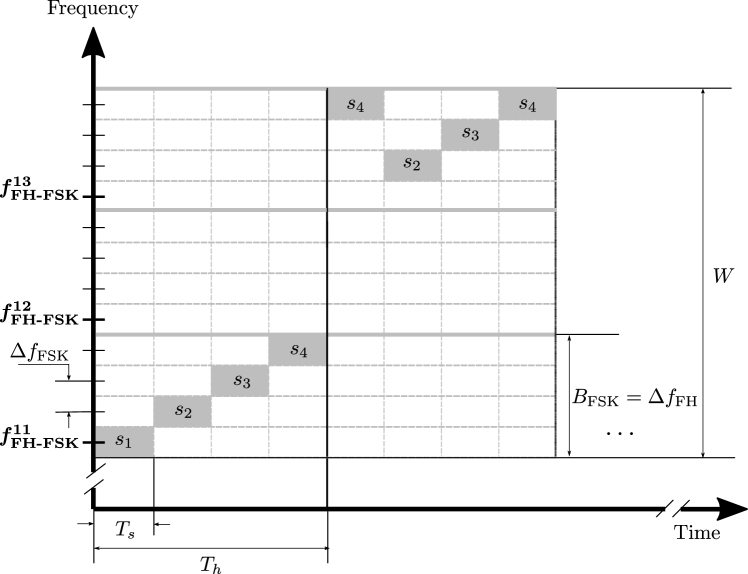
Despite their advantages, MFSK signals can be easily intercepted and, moreover, can be seriously distorted by frequency selective channels. These drawbacks can be overcome by means of frequency-hopping (FH) techniques [2, Chapter 13], which randomly change the carrier frequency in every hop period . We assume hopping frequencies that are randomly selected from a set of equally spaced frequencies , with being the separation between any two adjacent . We consider , hence the transmit frequency for every in FH-FSK is , whereas is the total transmission bandwidth. We focus on slow FH where (), as shown in Fig. 1, which contains the time-frequency plot of an FH-FSK transmission. Since demodulation requires knowledge of the pseudo-random FH pattern, FH-FSK prevents eavesdropping while increases robustness to frequency-selective channels.

Another concept, in line with IoT, is direct antenna modulation (DAM), which consists in modulating the carrier in the antenna itself [3, 4]. DAM replaces baseband modulation and significantly reduces transmission hardware (HW) complexity, cost, and power consumption [5, 6, 7]. Furthermore, since modulation occurs after amplification, power amplifiers only need to amplify a single carrier, hence avoiding wideband PAs.
This letter combines FH-FSK and DAM into a transmission method termed DAFH-MFSK and proposes an innovative approach for its implementation using a highly efficient and versatile single sideband (SSB)111SSB TMAs remove unwanted frequency-mirrored beam patterns produced by conventional TMAs to achieve high efficiency levels. TMA [8, 9, 10, 11, 12, 13] which, in addition, is capable of performing beamsteering.
II Joint DAFH-MFSK Modulation and Beamsteering: A TMA Approach
II-A SSB Time Modulating Feeding Network
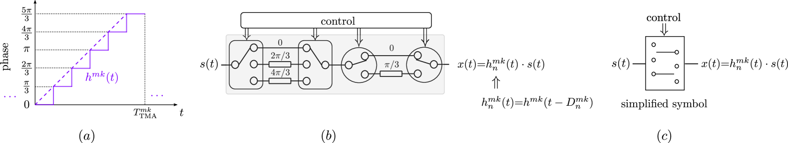
Fig. 2 plots the proposed SSB TMA architecture for DAFH-MFSK, equipped with periodic time-modulating feeding networks (TM-FNs) to jointly perform DAFH-MFSK modulation and beam steering. We consider a linear array of isotropic elements with unitary static excitations, , , and . The -th element excitation is modulated during a symbol period by the periodic pulsed signal , which is a time-shifted version of the stair-step approximation to (see Fig. 3a), an LP-TM waveform [12] with unit amplitude and phase varying from to (six steps). Therefore, , being a variable time-delay. Notice that has a fundamental period , where refers to the transmitted -th FSK-modulated level, and accounts for the hop frequency slot selected during .
The synthesis of is described using a switched TM-FN (see Fig. 3b). Considering the rectangular pulse signal when , and otherwise, we can express a single period of as . Hence, the exponential Fourier series coefficients of the periodic signal are:
| (1) |
The Fourier coefficients are the same for all values of and because is always a time-scaled version of the waveform shown in Fig. 3a. In view of Eq. 1, the Fourier coefficients of are given by
| (2) |
and the exponential Fourier series expansion of is
| (3) |
According to LABEL:eq:Fourier_coefficients_of_h^{mk}(t), Fig. 4 shows the normalized Fourier series power spectrum of in dB, namely . We can see, apart from the SSB property of the waveform, that the most meaningful unwanted harmonic is the one with order , whose relative level is at dB with respect to the useful harmonic .
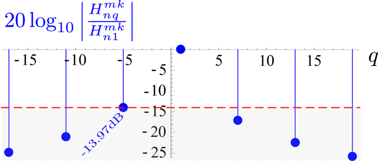
TMA periodic modulating signals, , have the following features: (1) they have no frequency-mirrored harmonics (hence the term SSB) and their first positive harmonic concentrates almost all the transmitted energy; (2) this harmonic is located at , hence the TMA transmits the -th level within the -th FH slot; and (3) the phase term of the first positive Fourier coefficient of is proportional to the time delay (see LABEL:eq:Fourier_coefficients_of_h^{mk}(t)), which is instrumental to determine the steering direction of the TMA beampattern and, unlike digital variable phase shifters in standard phased arrays, can be adjusted almost continuously [14, 15].
In addition to the rejection threshold of unwanted harmonics shown in Fig. 4, the time-modulation efficiency of the TMA is , where and are the respective useful and total average power radiated by the TMA. According to [16, Eq. 16], is given by
| (4) |
Since has unit amplitude, then
| (5) |
thus obtaining (see LABEL:eq:Fourier_coefficients_of_h^{mk}(t) and Eq. 4)
| (6) |
This means that the proposed SSB TMA architecture ensures that more than % of the total energy is transmitted over the first positive harmonic. On the basis of this result, the following approximation is applicable in Eq. 3
| (7) |
II-B Signal Radiated During a Symbol Period
As shown in Fig. 2, the input to the proposed SSB TMA is the single-frequency carrier signal . During a symbol period , the TMA excitations are time modulated by and the signal radiated by the TMA in the spatial direction is given by
| (8) |
where is the position of the -th array element on the axis and is the wavenumber for a carrier wavelength . Normalizing Equation 7 with respect to , which is the same for all values of and (see Eq. 1), Eq. Equation 8 can be rewritten as
| (9) |
where the term is the spatial array factor during and provides the beamsteering ability to the TMA. Indeed, the maximum of the radiation pattern can be pointed to the direction by adjusting the delays , , so that the following equation is satisfied
| (10) |
in which case the array factor is
| (11) |
On the other hand, the term in Section II-B allows the TMA to transmit the -th FSK level over the -th FH slot, and thus perform DAFH-MFSK modulation.
III Case Study and Comparative Analysis
This section has a twofold purpose: (1) Demonstrate the feasibility of the proposed technique by means of numerical simulations, and (2) compare it with conventional architectures performing FH-MFSK and beamsteering simultaneously.
III-A Numerical Example
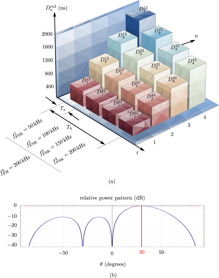
Let us consider a DAFH-MFSK modulator architecture based on TM-FNs (refer to Fig. 2). We assume the following parameters: carrier frequency: GHz; number of antenna elements: , spaced apart; modulation scheme: 4-FSK (); hopping frequencies: 6 possible values (); symbol period: ms; hop duration: , thus ms; frequency separation for FSK: kHz, with kHz; and frequency spacing for FH: kHz, with Hz. The minimum frequency of the TMA modulating waveforms is given by kHz, corresponding to their maximum possible period ms. Additionally, the TMA offers a minimum period of ns.
As an example, let us consider that the TMA radiates sequentially the four 4-FSK levels over the second () FH slot of duration and centered at frequency kHz. The frequencies to be transmitted and the antenna elements time delays , , (determined according to Eq. 10) to point the maximum of the radiation pattern towards are shown in Fig. 5 and summarized in Table I.

| \addstackgap[.5] | |||||
|---|---|---|---|---|---|
| \addstackgap[.5] 1 | 250 kHz | 500 | 1000 | 1500 | 2000 |
| \addstackgap[.5] 2 | 300 kHz | 417 | 833 | 1250 | 1667 |
| \addstackgap[.5] 3 | 350 kHz | 357 | 714 | 1071 | 1429 |
| \addstackgap[.5] 4 | 400 kHz | 313 | 625 | 938 | 1250 |
III-B Comparison with Conventional Techniques
Fig. 6 shows the block diagram of a conventional FH-MFSK transmitter followed by a standard phased array equipped with digitally tuned passive VPSs to perform beamsteering. Every , the incoming binary data bits are employed, via a multiplexer (MUX), to select the transmitting carrier frequency from a pool of possibilities. The FH-MFSK signal is generated by mixing the resulting MFSK modulated signal with a carrier obtained from a digital frequency synthesizer under the control of a code generator.
Given that the mixer produces both sum and difference frequency components, but only the sum frequency is intended for radiation, a bandpass filter (BPF) is placed after the mixer. Following amplification through the PA, the signal is radiated to a given direction by adjusting the VPSs within the standard phased array.
Compared with the conventional scheme in Fig. 6, our proposed TMA approach in Fig. 2 offers several key advantages:
-
1.
Reduced hardware complexity: In our approach, there is no need for a MUX, mixer, frequency synthesizer, or BPF, and the PA only needs to amplify a single carrier.
-
2.
Minimal oscillator requirements: Unlike the conventional scheme illustrated in Fig. 6, which necessitates multiple oscillators corresponding to the number of MFSK levels, , our approach requires just one oscillator. Refer to Table II where we employ big notation [17] for a comprehensive hardware comparison.
- 3.
-
4.
Improved insertion losses: For both the conventional architecture and the TMA approach, we consider off-the-shelf devices with the lowest insertion loss, denoted as , within the specified frequency band. Specifically, dB ( single-pole four-throw (SP4T) switch) [18], dB [19], dB [20], dB [18], dB [18], and ideal power splitters are taken into account.
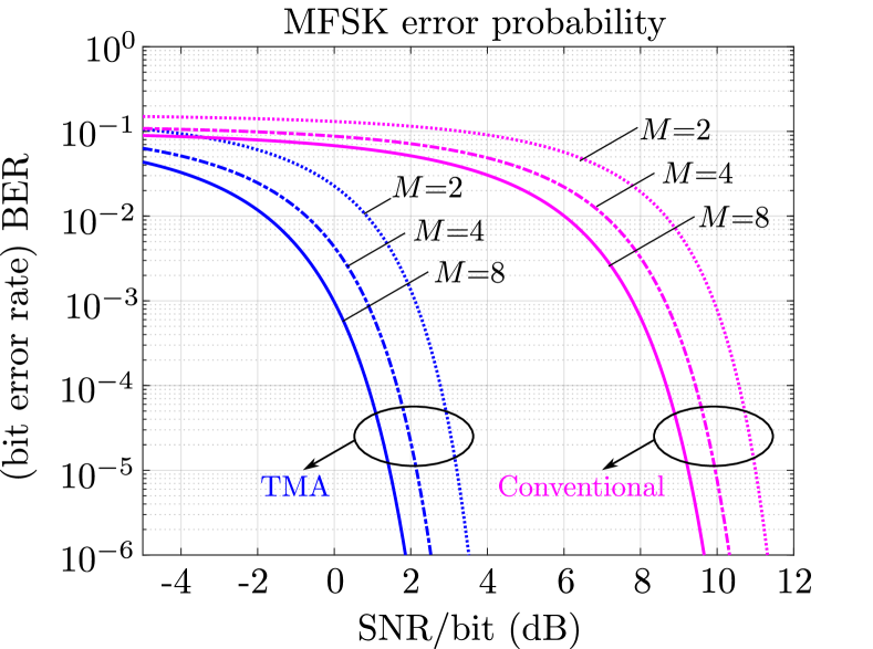
Under these circumstances, the conventional architecture exhibits an insertion loss of dB. In contrast, the TMA approach [21] demonstrates significantly lower insertion losses, with dB. Consequently, assuming equal power levels in the respective carrier signals, the same PA gain, and that the performance of all components remains consistent across the entire bandwidth, the proposed TMA approach achieves a substantial insertion loss reduction of dB. This insertion loss reduction leads to a significant performance improvement of MFSK demodulation in terms of bit error ratio (BER) versus received signal-to-noise ratio (SNR) per bit, as illustrated in Fig. 7.
| FH-MFSK & BS Scheme | # Oscillators | # SPDT switches | (dB) |
|---|---|---|---|
| Conventional (Fig. 6) | 11.2 | ||
| This work: TMA approach (Fig. 2) | 3.4 |
IV Conclusions
We have introduced an innovative TMA approach that seamlessly combines DAFH-MFSK modulation and beamsteering (BS), making it particularly well suited for low-power and low-data-rate applications. This approach offers several key advantages over comparable existing architectures, including better energy efficiency, simplified design, and the ability to achieve continuous phase-sensitivity beamsteering.
References
- [1] “Keysight application notes,” https://www.keysight.com/us/en/assets/7018-03097/application-notes/5990-8818.pdf, accessed: 2023-03-03.
- [2] A. Goldsmith, Wireless Communications. Cambridge University Press, 2005.
- [3] V. Fusco and Q. Chen, “Direct-signal modulation using a silicon microstrip patch antenna,” IEEE Transactions on Antennas and Propagation, vol. 47, no. 6, pp. 1025–1028, 1999.
- [4] S. Keller, W. Palmer, and W. Joines, “Direct antenna modulation: analysis, design, and experiment,” in 2006 IEEE Antennas and Propagation Society International Symposium, 2006, pp. 909–912.
- [5] S. Henthorn, K. L. Ford, and T. O’Farrell, “Bit-error-rate performance of quadrature modulation transmission using reconfigurable frequency selective surfaces,” IEEE Antennas and Wireless Propagation Letters, vol. 16, pp. 2038–2041, 2017.
- [6] ——, “Direct antenna modulation for high-order phase shift keying,” IEEE Transactions on Antennas and Propagation, vol. 68, no. 1, pp. 111–120, 2020.
- [7] P. James and R. G. Nair, “A study on adaptive direct antenna modulation,” in 2016 International Conference on Emerging Technological Trends (ICETT), 2016, pp. 1–6.
- [8] P. Rocca, G. Oliveri, R. J. Mailloux, and A. Massa, “Unconventional phased array architectures and design methodologies—a review,” Proceedings of the IEEE, vol. 104, no. 3, pp. 544–560, 2016.
- [9] R. Maneiro-Catoira, J. Brégains, J. A. García-Naya, and L. Castedo, “Time-modulated array beamforming with periodic stair-step pulses,” Signal Processing, vol. 166, p. 107247, 2020.
- [10] R. Maneiro-Catoira, J. Brégains, J. A. García-Naya, and L. Castedo, “Time-modulated phased array controlled with nonideal bipolar squared periodic sequences,” IEEE Antennas Wireless Propag. Lett., vol. 18, no. 2, pp. 407–411, 2019.
- [11] Q. Chen, J.-D. Zhang, W. Wu, and D.-G. Fang, “Enhanced single-sideband time-modulated phased array with lower sideband level and loss,” IEEE Transactions on Antennas and Propagation, vol. 68, no. 1, pp. 275–286, 2020.
- [12] G. Ni, C. He, Y. Gao, J. Chen, and R. Jin, “High-efficiency modulation and harmonic beam scanning in time modulated array,” IEEE Transactions on Antennas and Propagation, pp. 1–1, 2021.
- [13] E. Aksoy and E. Afacan, “Calculation of sideband power radiation in time-modulated arrays with asymmetrically positioned pulses,” IEEE Antennas and Wireless Propagation Letters, vol. 11, pp. 133–136, 2012.
- [14] Q. Chen, J. Zhang, W. Wu, and D. Fang, “Enhanced single-sideband time-modulated phased array with lower sideband level and loss,” IEEE Trans. Antennas Propag., vol. 68, no. 1, pp. 275–286, Jan. 2020.
- [15] Q. Zeng, P. Yang, L. Yin, H. Lin, C. Wu, F. Yang, and S. Yang, “Phase modulation technique for harmonic beamforming in time-modulated arrays,” IEEE Transactions on Antennas and Propagation, pp. 1–1, 2021.
- [16] R. Maneiro Catoira, J. Brégains, J. A. Garcia-Naya, L. Castedo, P. Rocca, and L. Poli, “Performance analysis of time-modulated arrays for the angle diversity reception of digital linear modulated signals,” IEEE J. Sel. Topics Signal Process., vol. 11, no. 2, pp. 247–258, Mar. 2017.
- [17] T. H. Cormen, C. E. Leiserson, R. L. Rivest, and C. Stein, Introduction to Algorithms, 4th ed. The MIT Press, 2001.
- [18] “Analog devices,” https://www.analog.com, SPDT switches. HMC284A, SP4T switches. HMC241AQ516, VPS HMC647A. Accessed: 2023-01-09.
- [19] “Mixer basics primer. markimicrowave,” https://markimicrowave.com/technical-resources/white-papers/mixer-basics-primer/. Accessed: 2023-09-24.
- [20] “Minicircuits,” http://www.minicircuits.com, Band Pass Filters: BFCN-2435+. Accessed: 2023-24-09.
- [21] R. Maneiro-Catoira, J. A. García-Naya, J. C. Brégains, and L. Castedo, “Multibeam single-sideband time-modulated arrays,” IEEE Access, vol. 8, pp. 151 976–151 989, 2020.