CRANE: A Redundant, Multi-Degree-of-Freedom Computed Tomography Robot for Heightened Needle Dexterity within a Medical Imaging Bore
Abstract
Computed Tomography (CT) image guidance enables accurate and safe minimally invasive treatment of diseases, including cancer and chronic pain, with needle-like tools via a percutaneous approach. The physician incrementally inserts and adjusts the needle with intermediate images due to the accuracy limitation of free-hand adjustment and patient physiological motion. Scanning frequency is limited to minimize ionizing radiation exposure for the patient and physician. Robots can provide high positional accuracy and compensate for physiological motion with fewer scans. To accomplish this, the robots must operate within the confined imaging bore while retaining sufficient dexterity to insert and manipulate the needle. This paper presents CRANE: CT Robotic Arm and Needle Emplacer, a CT-compatible robot with a design focused on system dexterity that enables physicians to manipulate and insert needles within the scanner bore as naturally as they would be able to by hand. We define abstract and measurable clinically motivated metrics for in-bore dexterity applicable to general-purpose intra-bore image-guided needle placement robots, develop an automatic robot planning and control method for intra-bore needle manipulation and device setup, and demonstrate the redundant linkage design provides dexterity across various human morphology and meets the clinical requirements for target accuracy during an in-situ evaluation.
Index Terms:
Image guided robots, CT guided robots, robotic biopsy, robotic ablation, medical robots, robot control, image guided surgery, interventional radiology (IR), workspace analysis, dexterous robots.I Introduction
Interventional radiologists (IRs) perform minimally invasive procedures under real-time medical imaging guidance, such as ultrasound, fluoroscopy, computed tomography (CT), and magnetic resonance imaging (MRI). In recent years, percutaneous CT-guided procedures have increased dramatically in both type and frequency due to their decreased complications and recovery time compared to more invasive open-surgery and laparoscopic surgery, enabled by technique and technological advances [1, 2]. They allow the minimally invasive diagnosis and therapy of numerous diseases. These include lung, liver, and kidney cancer and chronic lumbar-sacral spine pain, which in combination affect approximately one-in-six people during their lifetime [3, 4]. Lung cancer alone has approximately 230,000 new diagnoses and 150,000 deaths yearly in the United States [5]. Physicians use needle-like tools to diagnose and treat these diseases, including fine needles for injection and aspiration, core-biopsy needles, and ablation probes. Accurately needle insertion is challenging, especially for small lesions. This results in the average diagnosis necessitating 1.7 insertion attempts [6], in addition to frequent complications and a high repeat procedure rate of 43% [7, 6], with an increasing incidence of severe side-effects (including collapsed lung, up to 62.2%) for the patient and a 40-80% increase in cost attributable to repeat procedures [8]. Liver and renal procedures also have similarly high repeat procedure rates, costs, and accompanying side-effects for repeat procedures [9, 10, 11, 12].

Typically, CT-guided procedures involve multiple steps where the IRs alternate between manually and incrementally advancing the needle-like tool and stepping away from the gantry to scan the patient. The physician must balance frequency of scanning to understand the in-body environment with the radiation exposure for both the patient and physician. This trade-off directly affects tip-to-target accuracy [2], [13]. Frequently, the IR withdraws the patient from the imaging bore for needle insertion between scans for improved ergonomics. The combination of delayed feedback and freehand control presents a challenge when high accuracy is required and results in physicians performing a move-and-wait strategy [14] where they scan the patient, view the scan, make a conservative needle adjustment, and scan again.
Robotics can improve tip-to-target accuracy and ergonomics while decreasing radiation exposure by providing real-time visualization of the system state to avoid many of the current move-and-wait challenges and allowing for the precise adjustment of tools while the patient is within the bore [15, 16].
Many robotic platforms have been developed for transabdominal and trans-thoracic access, where the robot must ultimately operate well within the CT bore. Existing robotic platforms have demonstrated good needle placement accuracy, including small-size systems with low weight and large platforms with a fully active workspace and numerous methods of inserting needles [17, 18], and a variety of levels of human-involvement required during the procedure. However, existing systems fail to offer automatic hands-free device setup, control, and needle insertion within the imaging bore, resulting in performance compromises, the need for clinical workflow changes with increased overhead, the loss of existing abilities, or decreased safety in some situations [19, 20, 21, 22, 21, 12, 23]. This is partly due to limited exploration of the clinical considerations at the intersection of planning, design, and control for a large active workspace and high dexterity robot within the imaging bore, and the lack of comprehensive in-bore design dexterity evaluation methods.
In this paper, we present CRANE, shown in Fig 1, which provides a large workspace with high dexterity and accuracy with a simple automated method for in-bore robot control. Specifically, we tackle the challenge of designing a low-profile robot which has minimal backlash and high accuracy with sufficient dexterity and low artifact-generating metallic components, how to automate dexterous robot setup within an imaging bore for a needle insertion problem, how to evaluate a design early on in the development phase, and how to interface a robot with a needle-like tool such that both active insertion and passive guidance are supported. We previously presented the mechatronic design of CRANE with teleoperated control [24]; this works extends from that teleoperated approach and investigates the development and integration of an automated workflow, including analysis of the design’s dexterity, planning, and control for hands-free in-bore needle insertion. The novel contributions of this paper are as follows:
-
1.
Robot design for in-bore dexterity – a low profile and redundant serial link robot design utilizing outside-of-bore actuation with serial cable-driven in-bore joints and redundant sensing; achieving minimal in-bore footprint, dexterity to insert needles across a patient body, a large active workspace, passive backdriveability, and clinically required accuracy.
-
2.
Framework for in-bore planning and control of redundant robot – unified framework incorporating physician-specified task prioritizing for control of a redundant robot enables automated device setup operation. This framework is used for simulated design evaluation and control synthesis in-situ experiments.
-
3.
Comprehensive robot dexterity evaluation - a clinically representative in-bore robot manipulation dexterity evaluation is developed, including clinical and synthetic cases. This method can help improve robot design to maximize the possible needle insertion trajectories in patients, resulting in improved safety, ease of use, and a greater breadth of possible procedures with a single platform.
-
4.
Mechanism for grasping a needle – a novel clutching needle gripper using Shape-Memory-Alloy (SMA) actuator enables deep needle insertion with a short overall needle insertion mechanism length via electromechanical clutching. This mechanism allows for selecting active remote driving or physician-in-the-loop control where the system only provides insertion pose control without active insertion.
Our robotic platform, CRANE, tackles these main limiting issues via its novel mechanical design coupled with planning method while retaining the accuracy of previous systems. This provides the ability to work with patients of all sizes while automatically setting up the system, giving compatibility with off-the-shelf biopsy and ablation probes, and inserting the needle toward the target with only high-level control and minimal interaction.
II Clinical Procedure: Overview, Considerations, and Related Works
Surgical robots must carefully balance clinical value with workflow changes. Surgical robotics using image guidance (such as CT or MR) has a long history, including many of the first applications of robots within healthcare [25, 26]. However, image-guided robotics have only achieved strong clinical presences within orthopedic and neuro-surgery [27], where procedures are several hours long, and the systems operate outside imaging bores with less significant space constraints. Within Interventional Radiology, navigation systems that track the needle’s base position providing real-time needle visualization have received higher adoption due to their simple setup [28, 29] and have demonstrated improvements in clinical outcomes [26, 30, 12, 31, 32, 33, 34]. However, these systems’ performance is limited within the imaging bore [19] and have decreased clinical accuracy in comparison with robotic approaches [35]. Recent work presented many challenges relating to decreased adoption of image-guided robotics outside of orthopedic and neurosurgery [36] with a strong focus on the procedural workflow changes required to integrate the device overcoming their added value.
II-A Overview and Considerations
Imaging scanners, such as a CT scanner, comprise an imaging gantry and a couch. The imaging gantry has a bore that the patient resides within during imaging. The area between the patient, patient table, and the scanner bore is limited, placing in-bore space at a premium. An image-guided percutaneous surgical procedure has three main phases: Preoperative Setup, Procedure Planning, and Procedure Execution.
| Project | Mounting | Active DoF | Active Pos. Space | Active Ori. Space | Needle Insertion Method | In-bore Volume | Control Method | Manually Positionable |
|---|---|---|---|---|---|---|---|---|
| ZeroBot [37, 38] | Floor | 6 | Large | Large | Prismatic | Large | IK | No |
| [39, 40, 41, 42, 43] | Floor | 7 | Large | Large | Prismatic | Low | IK w/ col. detect. | No |
| Acubot/PAKY [44, 45, 46, 47, 48, 49, 50] | Couch | 6 | Medium | Medium | Prismatic | Low | IK | Yes |
| I-Sys/B-Rob II [21, 51] | Couch | 5 | Small | Large | Passive | Low | IK | Yes |
| Innomotion [52, 53, 54] | Couch | 6 | Medium | Medium | Prismatic | High | IK | Yes |
| Open 7-DoF [55] | Couch | 7 | Medium | Medium | Prismatic | Low | IK | No |
| LPR [43] | Patient | 5 | Medium | Low | Clutching | High | IK | No |
| CTBot [23, 56, 57, 58] | Patient | 5 | Low | Low | Clutching | Medium | IK | No |
| XACT [59] | Patient | 5 | Low | Medium | Gear | Low | IK | Yes |
| CRANE (ours) | Floor/Couch | 8 | Large | Large | Clutch | Low | Automated Planning | Yes |
-
1.
Preoperative Setup Phase – Before the surgery, the physician reviews the preoperative images to determine a rough plan of the procedure approach, including patient positioning (e.g., prone, supine, left or right lateral recumbent). If using a robot, the device is registered to the CT scanner coordinate system using an image-based alignment method so that the physician may physically operate in the scanner’s coordinate system.
-
2.
Procedure Planning Phase – With the patient in position, the physician takes an initial volumetric scan to provide an accurate view of the patient’s anatomy with which they can plan their precise needle-insertion approach. They must consider the in-body obstacles (e.g., bone, blood vessels, other organs) and the confined space they are working in (e.g., imaging bore, patient) to avoid collisions between the environment and the needle. With a robot, an additional challenge involves setting up the robot to the planned trajectory, assuming it is reachable and stable concerning the kinematics of the robot.
-
3.
Procedure Execution Phase – The physician inserts the needle into the patient towards the target point within the patient’s body. The physician alternates between making minor adjustments and inserting the needle with intermediate control scans. Upon complications or after multiple failures of attempting to navigate the needle to the target, the physician may loop back to Step 2 - Procedure Planning Phase, determine a new needle insertion trajectory and begin again.
II-B Related Works for Percutaneous Robotic Needle Insertion
| Category | Technology | References |
|---|---|---|
| Kinematic Design | Floor | [15, 60, 61, 38, 62] |
| Couch | [47, 21, 48, 55] | |
| Patient | [23, 63, 64, 65, 66, 67, 68, 69, 70] | |
| Dexterity Analysis | In-body | [71] |
| Out-of-body | [55] | |
| Active Needle Interface | Fixed Prismatic | [62, 55] |
| Clutching | [72, 73, 74, 75] | |
| Roller | [76, 77] | |
| Needle Trajectory | Manual | [60, 61, 38, 62, 23, 63, 64, 65, 66, 67, 68, 69, 70] |
| Automated | [78, 79, 80, 81, 82, 83, 84, 85, 86, 87, 88, 89, 90, 91, 92, 93] | |
| Robot Trajectory | IK | [60, 61, 38, 62, 23, 63, 64, 65, 66, 67, 68, 69, 70] |
| Path Planning | [94, 95, 96] |
This related work focuses on several device design attributes significantly affecting clinical workflow (e.g., device setup, control), value-add (e.g., accuracy, procedure time, general-purpose applicability), and safety (e.g., failure mode, device energy). The primary focuses are the device’s kinematic structure and workspace, needle interface, and automation level for planning and control.
We discuss and compare works focused on these attributes with multi-organ applicability in the thoracic and abdominal regions. Table I provides comparison of several fully-active systems which can adjust the needles angle and position.
II-B1 Kinematic Design: Device Setup, Workspace, and Safety
The surgical robot platform’s mounting location (e.g., floor, scanner couch, or patient) sets many constraints on the device’s kinematic design, size, and mass. This affects the device’s setup, workspace, and safety. Setup is frequently time-consuming and challenging and can require restarting from the beginning due to device self-collisions and environment collissions[25, 26, 97]. Large workspace fully-active systems provide many advantages, including lower procedure setup complexity, remote teleoperation, and the ability to regulate cartesian space tip stiffness to limit tissue damage in the case of gross or respiratory patient motion [98, 99].
Floor-mounted platforms (e.g., Innomotion, Maxio, Virtobot) are frequently fully active and simple to set up with large active workspaces. However, they can pose a safety risk in the case of relative motion between the patient on the scanner couch and the robot platform [15, 60, 61, 38, 62, 100, 101, 102, 103, 104]. [39, 40, 41, 42, 43] present a design with a fairly low in-bore profile using remote actuation via telescoping shafts and bevel gears with minimal metallic components, achieving MRI compatibility. However, the design suffers from high backlash (upto ) and is non-backdriveable. Frequently, these designs use industrial robots with a custom end-effector (EE), [100, 60] which occupy significant space within the scanner bore, have large inertia, and are not passively backdrivable. This limits the ability of the device to perform in-bore needle insertion, to adjust for unexpected patient motion safely, results in high energy within the system during robot motion, and is difficult to remove in case of system failure. Therefore, the needle insertions are typically performed outside the scanner bore and with the patient under general anesthesia with decreased accuracy, longer procedure time, higher risk of complications, and higher cost.
Couch-mounted systems (e.g. Acubot/PAKY, I-Sys/Biorob) [47, 21, 48, 55, 105, 106, 53, 52, 44, 89] may be fully active or partially active with the use of setup joints. These devices are attached to the couch and passively move with the patient during couch motion for intraoperative scanning. However, scanner attachment risks system damage and patient injury in the case of improper fixation [107]. [52] provides a fully active and backdriveable system with low backlash. However, the system occupies significant space ( cross section) and has limited joint travels. Manual setup joints significantly increase device adjustability while retaining a low profile and stiffness without backlash but are challenging to use and preclude the option of a fully automatic device setup. Instead, the physician must carefully manipulate the device to the correct position by hand while considering potential collisions with the environment. Many devices in this class use small, highly geared, non-backdriveable motors, which limits their dynamic performance and requires patients to be under general anesthesia.
Patient-mounted systems (including Light Puncture Robot, XACT, and Robopsy) are small and intrinsically compensate for gross patient and table motion improvement [56, 57, 63, 64, 65, 66, 67, 68, 70]. However, they frequently occupy more space in the scanner and possess less dexterity. Balancing system stability and patient comfort is also challenging when mounting to patients.
CRANE’s fully active workspace and redundant joints remove the requirement for manual device setup to a needle insertion transform while providing dexterity for needle insertion within a scanner bore. The transmission enables a low profile in the scanner bore, low backlash, low inertia, and backdriveability. This maximizes the space within the scanner for the patient, enables high accuracy and more straightforward device control, and improves procedural safety.
Throughout these device designs, in-bore workspace and dexterity analysis focus on swept volume accessible by the robot’s tip in free-space [23, 63, 66, 108], potentially with a single reference human body size [65] or the ability to reach target organs and tumors in specific patient cases [71]. [55] used orientable needle insertion evaluation on a demonstration human mesh surface as a proxy for in-body reachability. These evaluations have limited general-purpose applicability and do not consider dexterity in patients with large body habitus.
Here, we contribute a method and results for robot design analysis and planning to evaluate the general-purpose ability of a robot to perform dexterous in-bore needle insertion. Our method focuses on the area outside the patient: can the robot arm manipulate and insert a rigid needle-like tool into a patient’s body? We consider the ability to dexterously manipulate the needle around the nominal insertion point to enable adjustment for disturbances that may occur during insertion. Our analysis specifically focuses on a variety of clinically important metrics missing from prior approaches, including EE manipulability for task-space forces, torques, and position adjustments as required to advance the needle or adjust its base pose and to compensate for needle insertion error. This analysis is developed based on considerations across several clinical cases from which we construct a general and exhaustive evaluation across simulated procedures.
II-B2 Needle Interface
Needle interfaces assist a physician in inserting the needle into the patient while maintaining a target pose. They must be sterile, safe, and replaceable. Many needle interfaces exist, including passive guides [47, 44, 52, 74] and active mechanisms [72, 62, 55, 77, 76, 49, 16]. Passive guides orient and position the needle at the surface entry point where the physician manually inserts the needle. They decrease the unintentional application of torques and forces to the needle, deflecting it and decreasing accuracy.
Active needle drivers enable precise and quick insertion while the physician remains remote and away from radiation or contagious diseases. Existing active needle driver designs have utilized numerous mechanisms including limited travel prismatic axis [62, 55, 77], friction rollers [76, 77], clutching graspers [72, 73, 74, 75], and rack-and-pinion [16] while incorporating aspects such as force sensing and safety release [49]. These active designs have high complexity and limited replaceability resulting in potentially challenging sterilization procedures and limited compatibility with different needles and probes while providing sufficient gripping force to insert them without slipping at [109] or damaging the probe itself due to high Hertzian contact stresses[110]. Frequently, the designs require additional hydraulic or pneumatic lines which are difficult to interface on a disposable component.
Our presented clutching needle insertion mechanism uses a simple, fully solid-state design with a flexure-based needle interface providing low-manufacturing cost and active gripping only when power is applied. This supports single-use with pre-sterilization, even gripping force, and support for both passive guidance with the ability for the physician to advance or remove the needle by hand for improved safety.
II-B3 Automation Level - User Interface, Planning, and Control
Device setup and user control methods significantly affect the Procedure Execution Phase and fall into three main categories: direct joint control, EE control, and automated.
Direct joint control [111, 76, 112] has the physician manually control the robot joints. The system helps a physician perform a static insertion trajectory and achieve fine adjustment. Stereotactic frames are examples of this in image-guided surgery today. However, they can be complex and unintuitive to set up and plan for due to their frequently unintuitive kinematics and joint limitations [20].
Teleoperated EE control [113, 23, 63, 66, 55, 57] via Inverse Kinematics (IK), either in robot coordinates or image frame, allows a physician to abstract away the device’s joint motions and make precise needle adjustments. This is the most common operating model today, especially for small workspace and under-actuated systems, which require manual setup for rough positioning and do not have to solve large-scale motion planning problems for device setup. However, with this approach, the responsibility of considering potential collisions with obstacles in the environment and limitations of the robot’s dexterity is left to the physician operators, which is cognitively challenging to keep track of given the variety and complexity of linkage designs across different platforms. More broadly within the field of robotics, IK algorithms exist that locally consider collision avoidance, and device dexterity [114, 115, 116, 117] but have not yet been applied to the problem of in-bore needle insertion. A variety of techniques have been developed to minimize the effects of local minima on IK algorithms[118], including multi-start gradient descent and simulated annealing. Additionally, specialized methods for global optimization of IK solutions considering obstacles[119].
Automated EE control with planning directly in imaging space [120, 121] enables the physician to select their target needle insertion trajectory from which they guide the system to a course alignment. Then the robot automatically performs the fine adjustment based on image tracking, decreasing the physician’s cognitive burden and improving procedural accuracy [35]. However, the physician is still responsible for the device setup for course alignment and environmental collision considerations. Existing works have included methods for environmental and self-collision checking [42, 40, 39, 57, 122] prior to a commanded motion. However, the physician still must determine the collision-free robot configuration and trajectory them-self, in effect performing one of the most challenging parts of robot setup.
Collision-free motion planning from image-space needle trajectory allows the physician to select their target needle insertion trajectory and then allows the robotic system to solve the associated motion planning problem to avoid self and environment collisions while supporting angulation adjustment during the procedure. This is most relevant in large fully-active workspace systems, which can perform automated setup, allows the physician to focus on the higher-level surgical tasks, and decreases the cognitive overhead of introducing a robotic system. Ideally, the physician is confident in the system’s ability to follow through on this task regardless of the specific patient and needle insertion location. Previous works on collision-free planning for image-guided needle insertion provide methods of planning for nominal trajectory insertions outside the bore [94, 95, 96] or in simulation within a scanner bore [71] without considering dexterity required for needle pose adjustment around the nominal insertion pose for device kinematics or collision constraints with the imaging bore.
Significant research exists for assisting physicians in determining optimal trajectories for needle insertion within the patient’s body during the Procedure Planning Phase to perform the primary surgical task (e.g., biopsy, ablation, deep brain stimulation) while optimizing for a variety of objectives (e.g., obstacle avoidance, cranial-caudal needle angulation, needle deflection, tissue deflection, brachytherapy radiation distribution, ablation zone) from medical imaging data [123]. Many approaches exist for both straight [78, 79, 80, 81, 82, 83, 84, 85, 86] and steerable needles [87, 88, 89, 90, 91, 92, 93]. A select few of these methods integrate this in-body needle trajectory planning with robot planning for out-of-bore insertion [95, 96, 124] or within a simulated environment for in-bore [71].
Our robot configuration optimization method automates the robot setup and control given a target straight-line needle insertion trajectory specified by the physician while considering kinematic robot dexterity and environment collisions around the nominal needle insertion pose. This removes a significant cognitive consideration from the physician’s procedure planning
II-C Design Requirements and Specifications
For our system, we define the following design requirements and specifications. Our system performance, actuation, and sensors are summarized in Table III.
- 1.
-
2.
Passive Failure: system is hand back-driveable and applies of force when the system powered off.
-
3.
Precision: insertion requires position and orientation error [128]. Our system backlash should be significantly less than position and to provide fine adjustability without chatter.
-
4.
Workspace: Able to reach across a patient’s abdomen within a scanner bore, inserting up to [129] deep with a short insertion joint length, max cross-sectional dimension to preserve patient space, and adjusting orientation up to cranial-caudal and medial-lateral.
-
5.
Needle Interface: the needle interface should be easily replaceable, and able to function in both an active driving approach and passive guide modes.
-
6.
Imaging Artifacts: high-density materials (e.g. metals) cause reconstruction artifacts in CT images, reducing the physician’s ability to perform to see the target anatomy and perform the procedure. Actuators must be outside the bore or non-metallic.
| Specifications | Category | Values |
| Degree of Freedom | Positioning Joints | 8 Dof |
| Needle Gripper | 2 Dof | |
| Needle Insertion Mechanism | Length | |
| Accuracy | Positional | |
| Angular | ||
| Communication | Embedded | UDP |
| Desktop | TCP/IP | |
| Sensing | Motors | Opt. encoder |
| In-bore joints | Magn. encoder | |
| End effector | Magn. tracker | |
| Sensor resolution | Opt. encoder | |
| Magn. encoder | ||
| Magn. tracker | ||
| Backdriving force | Needle | |
| Trunnion joint | ||
| In-bore joints | ||
| Linear joints |
III System Design
The CRANE platform design focuses on dexterity, accuracy, and safety through its fully active design with precise transmissions, redundant sensors, and a fail-passive design (illustrated in Fig. 2 and with system specifications in Table. III). In the following sections, we will describe the analysis and modeling of the mechanics of the design, as well as supporting electrical and software system architecture.
III-A Mechanical Design for Dexterity and Precision
Needle entry point control for insertion requires manipulation with three Cartesian position constraints and two Cartesian orientation constraints (excluding roll around the needle’s primary axis)[130, 131, 132, 133]. The needle is advanced then along a typically linear trajectory with minor base position and orientation adjustments[134] along this constrained pose. A primary challenge is selecting the correct position and orientation for straightline needle insertion [135]. Furthermore, mechanical guidance increases accuracy over a real-time visualization of the needle’s trajectory [136]. Therefore, the device must have at least 5 degrees of freedom (DoF). Additionally, the robot’s joints and links must avoid obstacles (e.g., scanner gantry, patient, self-collision) while inserting and manipulating the needle. CRANE has 8-actuated joints for a 5-DoF problem space with three redundant joints, including a dedicated insertion joint. This enables CRANE to reach around the patient’s body to insert a needle while avoiding collisions and singularities.The system maximizes in-bore dexterity and active workspace while retaining a low profile by splitting the mechanics into two subsystems shown in Fig. 2: a large workspace out-of-bore base and a small intra-bore end-effector with remote actuation. The gross positioning stage is described below, and the end-effector will be further described in the following section.
The gross positioning stage comprises serially linked linear stages providing X-Y-Z cartesian motion with a large workspace ( in each axis), high precision, low friction, and low inertia with constant-force spring for Z-axis gravity compensation. Further details on the gross positioning stage are provided within [24].
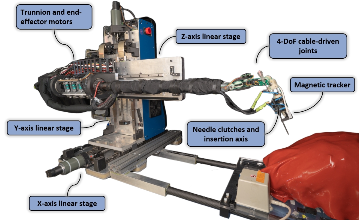
III-A1 End-effector
The distal end-effector enables dexterous needle manipulation within the tightly constrained space between the scanner bore and the patient. The end-effector has 5-DoF: 4 revolute joints for orientation control and a final needle insertion mechanism (described below) with a prismatic joint. cable transmissions couple the proximally located motors to the distal 4-DoF in-bore joints through a thin tube. Through a series of cable-driven joints, the motor volume and weight for the last DoF are isolated from the joints themselves, enabling a more compact design and thus greater workspace coverage, while low-gear-ratio motors can then be used to provide low reflected inertia to enhance backdriveability.
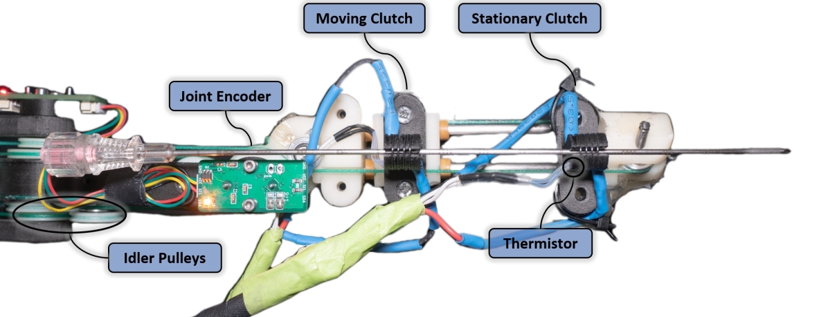
III-A2 Needle Insertion Mechanism
Humans perform needle insertion stepwise, iteratively performing short insertions and grasping the needle. On CRANE, the needle insertion mechanism mechanically imitates this insertion strategy and enables deep insertion within a constrained space. The needle insertion mechanism includes the cable-driven prismatic insertion axis, two-needle clutches, and a guide bushing for precise long-travel needle insertion with a limited travel prismatic axis. The two needle clutches (Fig. 3) are placed coaxially. One functions as a brake to prevent needle motion. The guide bushing additionally serves as a mount for the Ascension trakSTAR magnetic tracker and the CT alignment marker used for end-effector pose sensing (described in Section IV-B).
The needle clutch uses a Shape Memory Alloy (SMA) wire (Flexinol LT, ) helically wrapped around a flexure and actuated via Joule heating. When , the clutches is deactivated and acts as a guide. When heated , the wire contracts due to a crystalline structure change in the Nitinol from Martensite to Austenite. This length change applies a compressing the flexure into the needle. Experiments for measurements of slipping force, activation and cooling times, and lifespan were empirically tested (discussed in Section VI-B2).
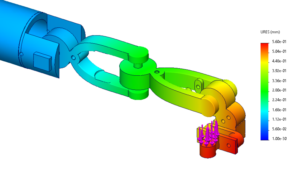
III-A3 Statics Analysis
Because of the long and thin arm section required to reach the patient within the scanner bore, stiffness analysis is performed. The EE’s links are constructed from carbon fiber-reinforced plastic (CFRP). FEA analysis, illustrated in Fig. 4, shows of tip deflection due to link deflection in a nominal configuration and a minimum factor of safety for all links.
Additionally, the cable transmission for the in-bore joints can exhibit deflection due to external forces and internal non-idealities, including friction, creep, and hysteresis. Static cable stretch is evaluated to determine its effect on system accuracy and stiffness. Cable stretch [137] can be modeled as:
| (1) |
where is the cable length change, is the cable’s Young’s Modulus, is the cable’s nominal length, applied force to the cable, and is the cable’s cross-sectional area. From this, angular deflection on cable-driven revolute joints can be calculated as:
| (2) |
where is the joint angle change due to cable stretch and is the terminating capstan pulley’s diameter. Transmission deflection due to cable-stretch results in end-effector stiffness when evaluated at the configuration shown in Fig. 4.
Modeling these two components as series springs, the combined system stiffness at the given configuration is:
| (3) |
Magnetic tracking of the end-effector enables the detection of link deflection, and joint-mounted magnetic encoders enable the detection of true joint position despite cable stretch. Feedback controllers (described in Section V-C) are applied to compensate for these errors. The modeled system stiffness was experimentally validated by applying a 5N (QWORK Slotted Weights) load to the robot’s end-effector and measuring deflection using a dial indicator (Clockwise Tools, 0.03mm resolution) across 5 trials and resulting in with joint controller and without, corresponding to and , comparing closely to our analytical calculations.
The transmission’s static load rating is analyzed to evaluate the design’s ability to exert the forces required for needle insertion and provide sufficient stiffness. The end-effector’s idler pulleys are the weakest component. Pulley wrap angles and the associated transmission load ratings change depending on the robot configuration. Configuration-dependent pulley load can be calculated as
| (4) |
where is the normal force on the idler pulley’s bearings, is the cable tension, and is the pulley’s wrap angle. The pulley wrap angle is represented as where is the current joint angle and is the cable wrap angle at the robot’s nominal configuration which is varies based on the idler due to the robot design. At a configuration, a joint transmission’s load rating is modeled as if a revolute joint or directly as if a prismatic joint. is the joint pulley radius and is defined as:
| (5) |
for each joint angle, , in the joint’s range, , and every joint, , in the cable-driven end-effector’s joints, . is the rated pulley load. The pulley load rating was evaluated throughout the joint range using the idler pulley’s bearing load ratings (R2-5 bearing, static radial load). The transmission is rated for , , , and for the revolute and prismatic cable-driven joints from proximal to the distal end.
III-A4 Joint Space and Actuator Space Relationship
Actuators are coupled to the joints via the transmissions described in the previous sections. The base joints and trunnion joint, , are directly actuated via permanent magnet motors, have simple gear-ratios relating to actuator and joint spaces. The cable-driven in-bore joints, , are coupled due to the changing wrap angle on idler pulleys for cables passing over previous active joints. This relationship is modeled as:
| (6) |
for joint positions, , motor positions , , and coupling matrix . is represented as a block diagonal matrix:
| (7) |
for the gear ratios for and the coupling matrix for
| (8) |
is found analytically and is diagonal due to the uncoupled design. is found via least-squares regression with motor encoder measurements as inputs and joint-mounted encoder measurements for as:
| (9) |
for each row of with is a time series of samples of a single joint’s angle measured directly via magnetic encoder and is a matrix time series of all motor angles. This results in:
| (10) |
is lower triangular because of positional coupling between preceding and following cable-driven joints.
III-B System and Software Architecture
The system architecture (Fig. 6) focuses on safety and extensibility. Real-time Embedded Computers (FPGAs and microcontrollers) run high frequency and timing-jitter sensitive control, allowing for independent development and upgrade of the high-level control system. The Desktop Computer hosts the user interface and high-level robot control, including kinematics and path planning.
User Datagram Protocol (UDP) over Ethernet with a dedicated network switch provides an extensible interface between computers. There are two primary electronic subsystems: Motor Controller and Clutch Controller. These components interface with the primary control computer, which performs high-level system coordination and user interface. Watchdog timers, redundant position sensors, mechanical gravity counterbalance, and error detection algorithms improve safety and enable a fail passive design. An Ascension trakSTAR magnetic tracker provides direct tip position and orientation sensing for the robot’s end-effector’s tip near the needle insertion point.
Robot Operating System (ROS) forms the basis for the multiple processes on the Desktop Computer via a standard messaging system. The Desktop Computer runs the less timing-jitter sensitive software, including robot kinematics and planning, image guidance, and user interaction. The device’s multiple user interface options provide flexibility depending on the situation and physician’s preference. The primary User Interface interface is a Qt5-based graphical user interface that handles system initialization and setup, direct joint level control, end-effector control, and automated control incorporating path planning (described below in Section V). Further details on the electronics and software architecture are provided within [24].
IV Coordinate Systems and Transforms
This system has three reference coordinate systems: the CT scanner, the magnetic tracker, and the robot. Homogeneous transforms provide relationships between coordinate frames, represented as
| (11) |
providing the transform from to relative to basis vectors for rotation matrix and translation vector . Typically the basis vectors are excluded from the transformation notation and assumed to be their system’s base coordinate system. Transformation matrices represent both transforms between coordinate systems (as an operator) and poses within a coordinate system.
The CT scanner and magnetic tracker are both sensors used as inputs to our system, with the robot as the primary coordinate system used internally. The transformation matrices below define poses relative to the three fixed reference coordinate systems relevant to our system.
Key poses defined relative to the CT scanner base frame, , are:
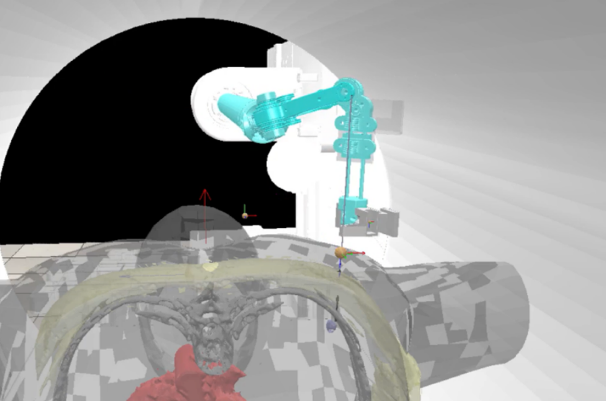
-
•
defines the Target Needle Insertion pose. This is typically on the patient’s skin and serves as the Remote Center of Motion (RCM) location for adjustments made after insertion. This is created based on input by the physician using the GUI. is initialized to . Each time the user presses a GUI button corresponding to a X, Y, and Z cartesian translation directions or roll, pitch, and yaw orientation adjustments, for the corresponding unit translation or rotation homogeneous transform . The magnitude of is specified by a GUI slider.
-
•
defines the pose for the spherical CT-visible fiducials, , within the CT scanner frame and embedded in the magnetic tracker mount used for referencing the robot and scanner’s coordinate system. These are located during the calibration step within the CT images (described in Section IV-B).
Key poses defined relative to the magnetic tracker base frame, , are:
-
•
, define the pose of the magnetic tracker mounted to robot tip and phantom; measured by the Ascension trackStar magnetic tracker at .
-
•
, is the static transform to each CT-visible fiducials relative to the magnetic tracker used for referencing the magnetic tracker and scanner’s coordinate systems.
Key poses defined relative to the robot base frame, , are:
-
•
defines the robot’s EE pose calculated via the Forward Kinematics function (defined in Section IV-A). This pose is attached to the needle insertion mechanism’s needle guide, and the Z-axis is coaxial with the needle grippers and needle guide directed distally to the robot.
-
•
, is the static transform from the robot’s EE to the magnetic tracker mounted on the robot needle guide.
The transforms between the three coordinate base frames are calculated in a pre-procedural calibration step providing , between the magnetic tracker’s base and the robot base, and , between the scanner’s base and the robot base (described in Section IV-B).
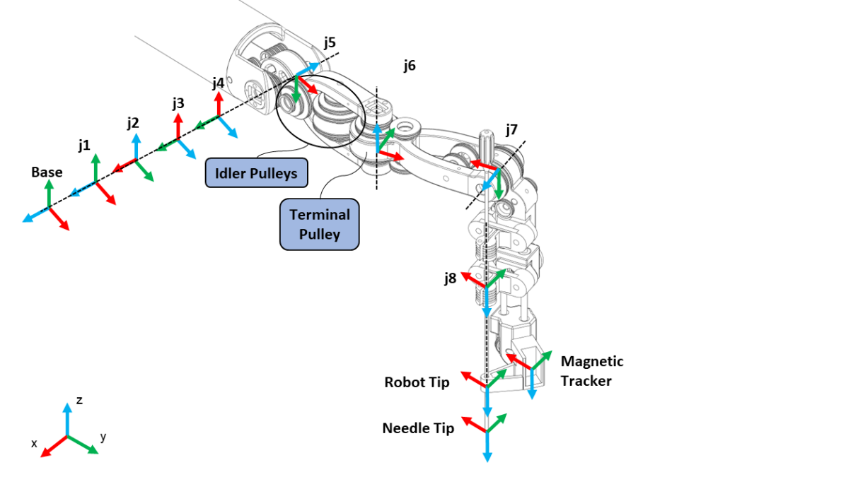
IV-A Forward Kinematics
The robot’s kinematics chain is described using Modified Denavit-Hartenberg (DH) Parameters which attaches coordinate systems to each joint of the robot and defines the transform between these coordinate frames as where
| (12) | |||
| (13) |
and is substituted into for prismatic joints and is substituted into for revolute joints.
The forward kinematics function , defines the robot base to end-effector (EE) transform by chaining together the transforms described by the DH convention:
| (14) |
with DH-parameters provided in Table IV.
| Frame | Type | ||||
|---|---|---|---|---|---|
| 1 | p | 0 | |||
| 2 | p | 0 | |||
| 3 | p | 0 | |||
| 4 | r | 0 | 0 | 0 | |
| 5 | r | 0 | 0 | ||
| 6 | r | 7e-2 | 0 | ||
| 7 | r | 7e-2 | 3e-2 | ||
| 8 | - | 1e-2 | 2e-2 | 0 |
IV-B Magnetic Tracker, Scanner, and Robot Calibration
The robot to magnetic tracker calibration, , and robot to scanner calibration , transforms are calculated based on a calibration procedure to minimize a least squares error.
| (15) |
where is the calibration transform between robot base frame and the target base frame. are the augmented Cartesian calibration point sets for sample points and .
For , a calibration trajectory is performed using the robot’s linear base joints, . Each sample for and for the corresponding timestep . For , a single CT scan is taken and processed to localize the fiducials within the scanner’s coordinate system. Each sample for and are the measured positions of the fiducial’s centroids found within the CT image. For CRANE, the rigid body markers consists of multiple CT visible fiducial spheres (Beekley CT-SPOT 120) (Fig. 7).
V Automated Robot Trajectory Planning
| Symbols | Definition |
|---|---|
| , | joint and actuator configuration |
| trajectory of joint configurations expressed as a matrix | |
| set of poses | |
| set of obstacles | |
| dimension of a configuration, i.e., the DoF of the robot | |
| , , | transformation matrix |
| comprising rotation matrix and translation vector with rotation sub-matrix and translation sub-vector | |
| rotation matrix via Rodrigues’ formula around axis an angle of | |
| Configuration space (C-Space) | |
| distance to obstacles in Workspace | |
| task orientation difference between poses | |
| position difference between poses | |
| zenith angle for conical RCM adjustability evaluation | |
| Forward Kinematics pose | |
| , , | Jacobian matrix, damped inverse Jacobian matrix, and damping term |
| wrench | |
| , , | pose error tolerance consisting of position and orientation |
| pose error vector comprising position and orientation | |
| configuration cost function | |
| , | actuator to joint space matrix and actuator controller gains |
| actuator torque |
This section describes a method enabling the robot to safely and dexterously manipulate a needle within a scanner while avoiding collisions with the environment, enabling the physician to be hands-off during device setup. This is accomplished via a hierarchical planning and control scheme for two phases of the procedure: Automated Device Setup to during Procedure Planning Phase and fine adjustment of the robot’s configuration around during Procedure Execution Phase. For device setup, an optimal Dexterous Device Setup Configuration, , for is determined. Then, a collision-free configuration space trajectory, , is determined using a sampling-based motion planner ( BiRRT implemented in OMPL [138]). Once is executed, a Local Controller is used for servoing the end-effector in the case of small adjustments of .
V-A Dexterous Robot Setup Configuration: Problem Definition
A Dexterous Robot Setup Configuration is one for which the robot can feasibly insert a needle into the patient and manipulate the needle around the nominal . This is defined based on several metrics, including joint limits, workspace singularities, and collisions with the environment. The C-space where is the robot’s number of joints defines the possible robot configurations and contains the following important sub-spaces for our optimization problem:-
-
1.
Feasible C-space, , can apply sufficient forces and moments to insert and adjust the angulation of the needle.
-
2.
Collision-free C-space, , where is sufficiently close to .
-
3.
Collision-free C-space, , where the robot is sufficiently far from a collision with obstacles, including environment and self-collisions.
-
4.
Adjustable C-space, , where the robot can perform an RCM adjustment around the Target Needle Insertion pose for a defined conical region.
For our needle insertion task, we define comprising non-singular configurations where the system can manipulate a needle with sufficient force. The Jacobian matrix, and denoted as , relates EE twists, and joint velocities, as well as relating EE wrenches, , and joint torques, :
| (16) |
The space and body Jacobians, and , represented in the robot’s base coordinate system and coordinate systems are used throughout this section. Using these relationships, is:
| (17) |
where is the required force and moment to insert and manipulate the needle represented as a wrench in the frame and is the robot’s maximum joint torques.
Furthermore, we define as configurations with the robot’s EE near the Target Needle Insertion pose . The function computes the vector difference between the position vectors of two poses and computes the axis-angle difference between the Z-axis of two poses:
| (18) |
| (19) |
where and are the Z-axis vectors of the rotation matrix from their corresponding poses. Using these difference functions, is:
| (20) | |||
where is a predefined position error tolerance and is a predefined orientation error tolerance.
The obstacle-free C-space is the set of robot configurations in which the robot’s links are sufficiently far from obstacles, , (e.g., scanner, patient, self-collisions):
| (21) |
where is the minimum distance from the robot to obstacles and is a specified minimum distance to collision for environment padding.
Finally, we define comprising the region of the configuration space where the robot can perform an RCM adjustment of the needle in a conical region around the current configuration:
| (22) | |||
Robot configurations and are connectable if a simple Local Planner can provide a collision-free trajectory, , between them. Here, the Local Planner is a gradient descent IK method with a nullspace objective. is a pose within where are the space of homogeneous poses within a conical orientation adjustment of . is constructed using which defines the rotation matrix from an arbitration rotation angle, , around an arbitrary axis, , via Rodrigues’ Formula as:
| (23) | |||
where is the zenith angle of the conical region, is the transform used for RCM angle adjustment defined with with rotation submatrix and translation subvector . and are the rotation matrices around the and axis for RCM orientation adjustment, and the translation is zero due to the RCM motion constraint. Only angulation adjustments are evaluated as the needle is inside the body, and translation would result in significant forces being applied to the tissue.
Using the defined C-space, corresponds to minimizing a corresponding cost function:
| (24) |
where can be defined arbitrarily. Our focusing on maximizing dexterity and distance to collision while minimizing joint motion is defined as:
| (25) |
where are the optimization priorities, is a modified version of Yoshikawa manipulability index [139] for the configuration calculated using the rows of the body Jacobian corresponding to roll and pitch orientation axes. Other common dexterity indices[140, 141] can also be applied. is the minimum distance-to-collision between the robot and the scanner bore, is the minimum distance-to-collision between the robot (excluding needle insertion mechanism) and the patient, and is the distance from the evaluated robot configuration to initial robot configuration.
V-B Dexterous Robot Configuration Generation
A general-purpose global optimization algorithm [142] with directly turned into an inequality constraint is used to determine . Eq. (24) and are directly evaluated in the main optimization function with , , and . The obstacles set for our optimization is .
For a redundant robot, the joints can be partitioned as for the non-redundant joints, , and redundant joints with respective non-redundant C-space and redundant C-space . Correspondingly, can be reorganized into redundant and non-redundant block matrices:
| (26) |
where corresponding to the non-redundant joints and corresponding to the redundant joints.
The function jointly evaluates the optimization objectives and if . returns and if or otherwise returns a large cost, , and, initial joint configuration, . IKConfigurationLoss evaluates a nominal robot configuration’s dexterity. The nominal configuration is determined by fixing to the configuration determined by the global optimizer to resolve redundancy and solving for using with a gradient-descent-based IK formulation. For CRANE, , , and is excluded.
IK is implemented following the Levenberg-Marquardt algorithm for stability near singularities with damping term . The pose error between two poses is calculated as the cartesian position error and axis-angle orientation error between the pose’s vectors. During the Solve IK portion of IKConfigurationLoss, a nominal IK solution is found for with , providing a full robot configuration, , when combined with from the general-purpose global optimization algorithm.
During Evaluate Adjustability of IKConfigurationLoss, the nominal joint configuration is evaluated for RCM adjustability as defined in Eq. (22). creates a set of adjustable angle target poses around satisfying the RCM constraint by rotating the nominal insertion pose. During this evaluation, the full Jacobian, , is used with a nullspace objective to remain near the previously determined nominal robot configuration. For each step of the gradient-descent, is evaluated for if it remains within . This evaluation implicitly checks the path between and is collision-free due to the limited step size of the gradient step. specified as a large value for in-collision configurations and is selected sufficiently large that it is greater than any cost from . Depending on the cost function weighting, different robot configurations are optimal (Fig. 8).
V-C Local Controller
The local controller minimizes the distance between and estimated EE pose, , calculated from the measured tip-mounted magnetic tracker’s pose for feedback to compensate for system mechanical deflection (described in Section III-A3). This is calculated as:
| (27) |
Additionally, the local controller minimizes the distance between the estimated joint configuration, , and via a nullspace controller. Specifically, the joint configuration setpoint, , is updated following:
| (28) |
| (29) |
where with damping term evaluated at the estimated joint configuration, and are end-effector and null-space task gain matrices, , the target pose described by defined above and with provided from the User Interface. The estimated joint configuration, , is described in the following section.
V-D Robot Joint Control
The robots joint configuration estimate, , is calculated as:
| (30) |
for motor position, , motor velocity , sampling time, , and weighting parameter, , setting the complementary filter’s changeover frequency. The base joint positions are calculated based on the gear ratios and can be directly used for control due to the transmission’s high stiffness. The in-bore cable-driven joint configuration, , is estimated using a complementary filter between the joint mounted magnetic encoders (AMS AS5048B), , and motor’s velocity, , (Maxon ENX encoder, Maxon ESCON 50/5) to compensate for errors in the coupling relations due to the cable transmission’s stretch and hysteresis, and the joint encoder’s noisy readings.
Motor torque setpoints, , are calculated based on the error between the target joint configuration, , and the current joint configuration estimate, , as:
| (31) |
where and are the actuator-space proportional and derivative gains.
VI Experiments and Results
VI-A Simulated Dexterity Analysis
Using the Automated Device Setup method described previously, CRANE’s kinematic and static dexterity is evaluated across several simulated environments. This method enables the evaluation of kinematic designs for in-bore surgical manipulation, considering the limited space and variety of patient body habitus and insertion points that may be encountered clinically. Two environment styles are tested: retrospective clinical cases for needle biopsy in a scanner and comprehensive simulated cases. CoppelliaSim[143] with PyRep[144] bindings provides distance-to-collision, , calculations.
reachable
reachable
reachable
reachable
reachable
reachable
VI-A1 Retrospective Clinical Cases
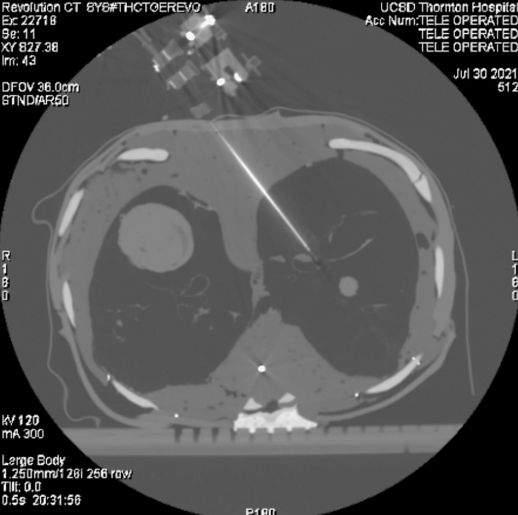
The volumetric CT scans (DICOM format) of six transthoracic CT lung biopsy cases (Fig. 9) from UCSD Health were segmented and integrated into a CoppelliaSim environment. The environment consists of collision meshes, , and . Furthermore, a synthetic patient body is generated using STAR [145] based on the patient’s body habitus to fill in the portion of the patient’s body not visible in the clinical scan.
This experiment evaluates the system’s ability to reach for the Automated Device Setup method, while satisfying the prerequisite optimization constraints. is attached to the segmented patient body which is placed within the scanner such the the DICOM’s isocenter aligns with the scanner bore’s isocenter. An individual is reachable if a dexterous configuration was found by the Automated Device Setup method and determined by . All six retrospective cases were reachable. This illustrates CRANE’s ability to automatically setup for dexterous needle insertion within a clinical environment.
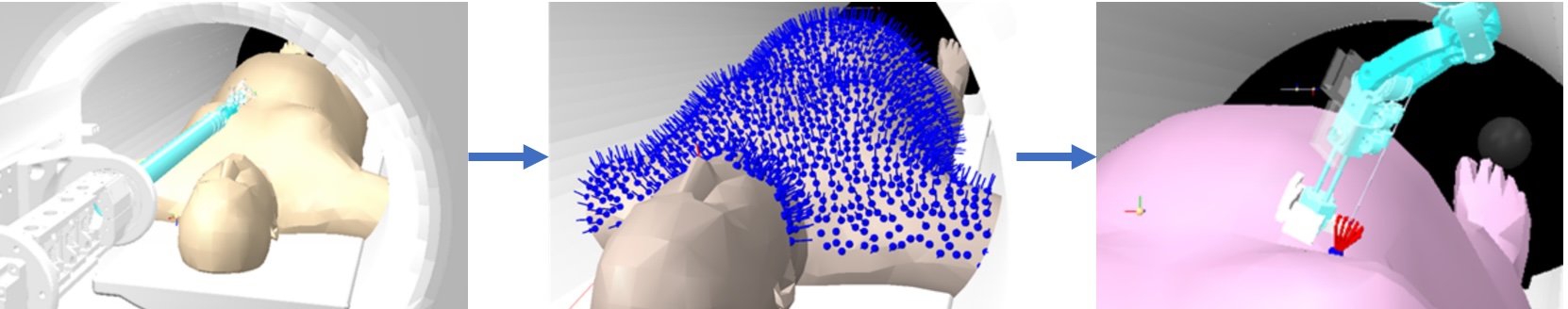
VI-A2 Comprehensive Simulated Clinical Cases
Motivated by the retrospective clinical cases, a comprehensive test was created to enable the general purpose evaluation of an in-bore needle insertion robot’s dexterity. Different sizes of human bodies were generated using STAR[145] to BMI for U.S. males and females. Larger patients result in less in-bore space and a more challenging environment. These human bodies are placed within the scanner bore following the procedure described above in Section VI-A1. This test results in visual plots of a robot’s ability to dexterously insert needles across a variety of patient bodies at various angles.
For each environment’s human body mesh , a set of , , is created from the mesh vertices and surface normals, , of the simulated patient; defined as:
| (32) | |||
where and and is the Z-axis unit vector. Physicians typically insert needles in an orthogonal fashion to the patient’s skin to prevent slipping and needle bending from tissue boundary layers. Therefore, the surface normal vector is used as a the nominal insertion vector. However, off-normal insertions are also performed clinically and are additionally evaluated around the nominal surface normal (shown in Fig. 10), providing a set of insertion poses for an individual vertex connected pose as:
| (33) |
Given this set of Target Needle Insertion points for a single vertex, , the robot’s ability to perform the insertion dexterously is evaluated using the Automated Device Setup method (described in Section V) and returning . An individual is reachable if a dexterous configuration was found by the Automated Device Setup method and determined by .
We conducted paired Student’s T-tests to compare different combinations of robot types (5-DoF, 6-DoF with Insertion, 7-DoF with Insertion and Yaw, 7-DoF with Insertion and Pitch, and 8-DoF) across concatenating all of the various patient body habitus reachability performances into signal sets per robot joints used in the evaluation. A significance threshold of was applied to assess whether these combinations belonged to the same distribution. The results indicated that the combinations 5-DoF, 6-DoF with Insertion, 7-DoF with Insertion and Yaw, 7-DoF with Insertion and Pitch, and 8-DoF had and were statistically significant. However, for the combinations 7-DoF with Insertion and Yaw and 7-DoF with Insertion and Pitch, the , and we could not reject the null hypothesis of them belonging to the same distribution.
As shown in Fig. 10, CRANE can dexterously insert needles across patients with a wide variety of body sizes and morphology. Large patients decrease the accessible dexterous region and are primarily limited by the length of the robot’s final EE insertion axis, shorter than many needles used during clinical procedures and therefore not a significant limitation. This test shows that CRANE’s low profile design and the redundant kinematic chain enable the dexterous insertion of a needle for clinical cases.
VI-B Robot Experiments
VI-B1 Trajectory Tracking
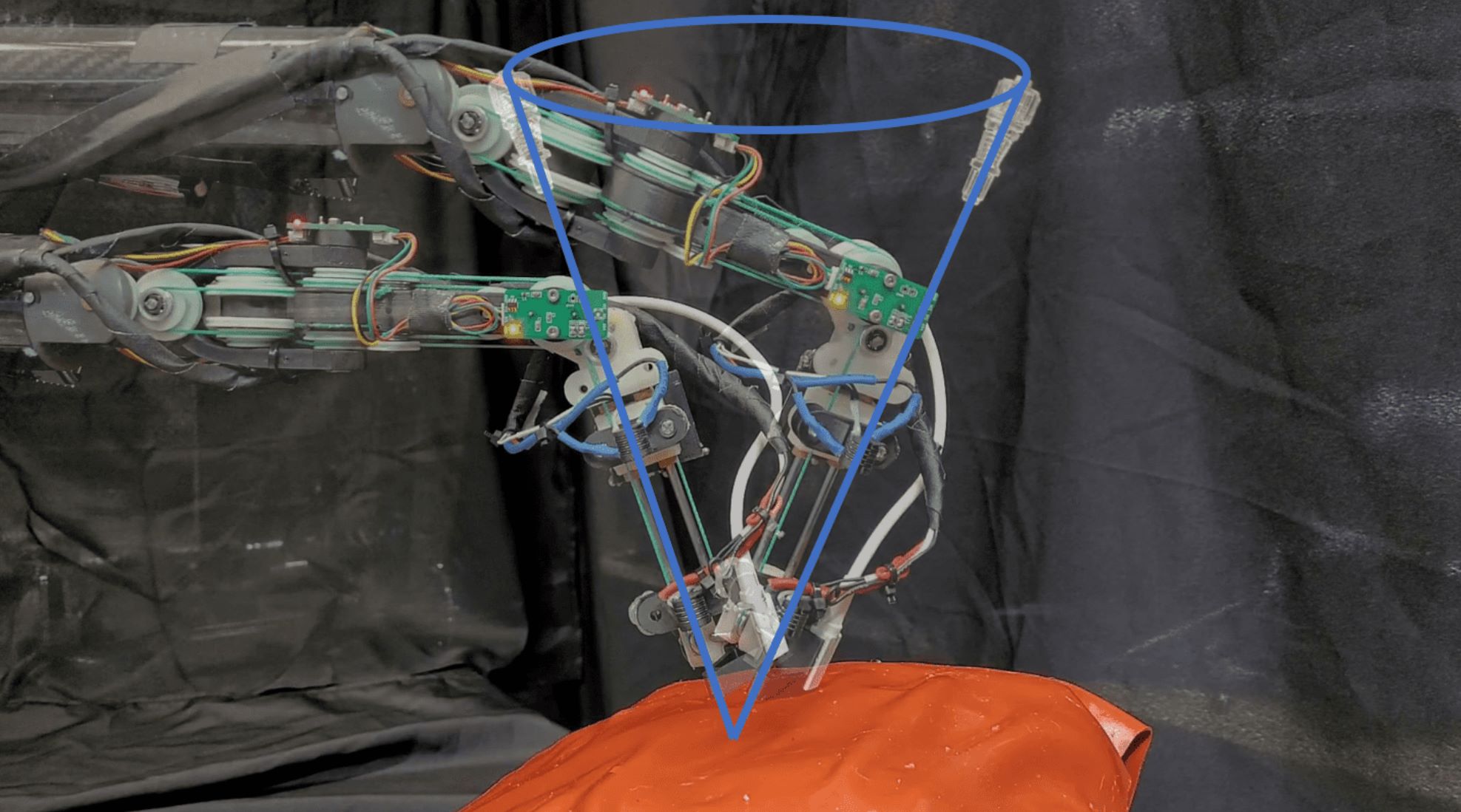
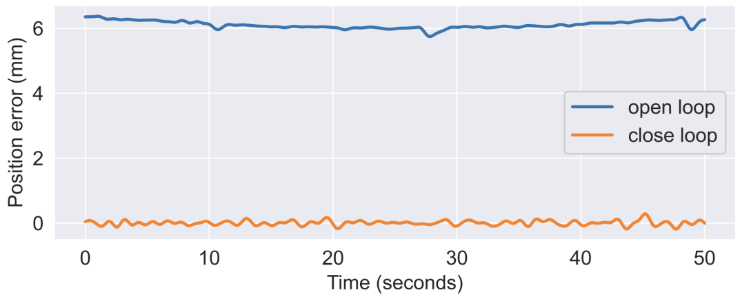
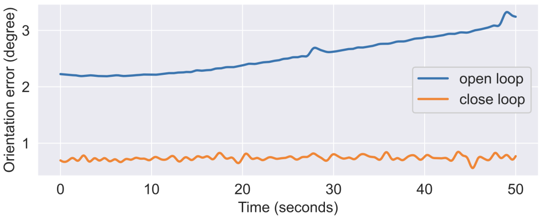
The system’s open loop accuracy and closed loop servoing performance was evaluated by performing a virtual Remote Center of Motion trajectory where the robot revolved around a virtual needle tip location using the experimental setup shown in Fig. 2. Here, the robot’s end-effector follows a cone trajectory simulating the workspace a physician would use during an actual procedure. The Ascension TrackStar magnetic tracker was used for accuracy measurement in the open-loop test and feedback reference for servoing performance in the closed loop test. The mean resulting closed-loop servoing performace, shown as a time series in Fig. 11, across the trajectory was and . The Ascension Trackstar is rated for RMS accuracy numbers of and .
In the open-loop test, joint and end-effector controllers were disabled. Joint angles were calculated off the ideal coupling matrix, , without compensation for cable stretch and hysteresis in the in-bore transmission. EE measurements were replaced for the controller with predicted EE positions based on the forward kinematics of the calculated joint angles from the motor. With controllers disabled, position and orientation errors are increased due to joint tracking errors, system deflection, and manufacturing errors. Closed loop trajectory tracking using direct end-effector tracking enables the system to accurately reach targets despite these challenges.
VI-B2 Needle Gripper: Slipping Force and Speed
Performance regarding clutching force, cycle time, insertion force, and thermal transfer to the needle are evaluated. The needle clutch is 3D printed in a nylon-carbon composite material. The clutches are designed to grip a 15-gauge needle. Slipping forces were measured using spring scales ( and ranges). Activated slipping forces are and Deactivated slipping forces are at and . This compares favorable to [127], where was the maximum achieved.
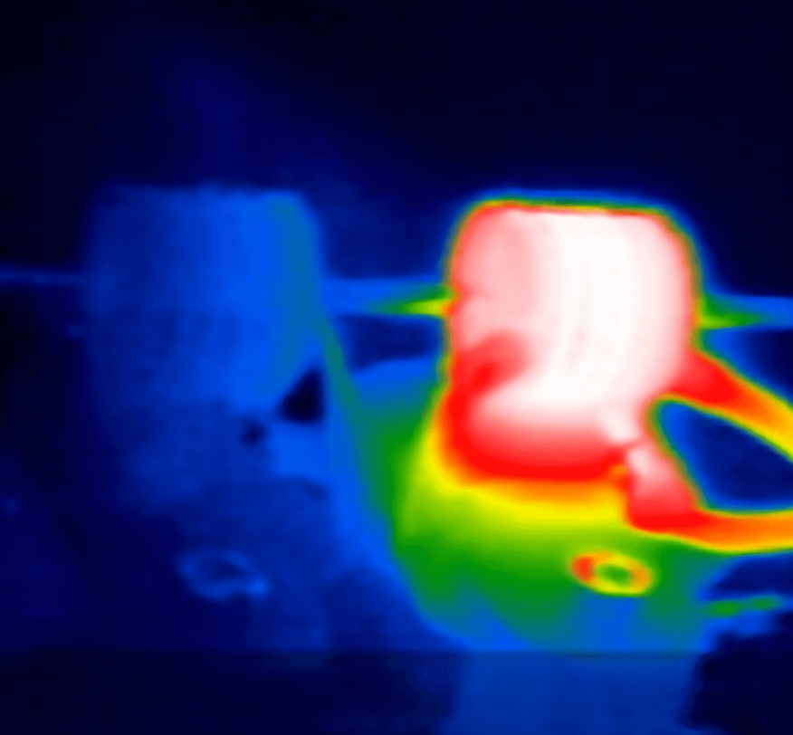
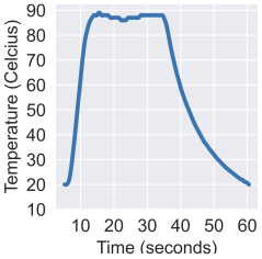
Additionally, a step-response test was performed. The results, reported in Fig. 12, show short on and off times, implying the possibility for rapid clutching for deep needle insertion and clutch deactivation for safety.
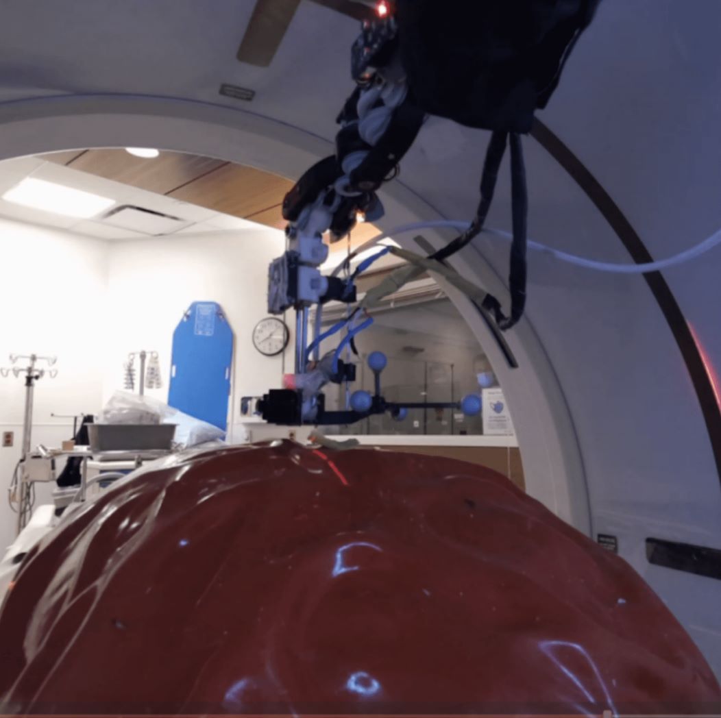
VI-B3 Clinical Validation: Phantom Study in CT scanner
Multiple in-situ needle insertions were performed using CRANE and CT guidance on a custom static lung phantom to evaluate procedural feasibility. The static lung phantom comprises a plastic resin rib cage, a preserved and dried pig lung, and multiple tissue layers. Teleoperated, closed-loop image servoed, and single-shot automated procedures were performed. The needle is aligned to a target trajectory and then advanced. The null-space controller is disabled for these tests.
During the teleoperated experiment, an interventional radiologist controlled the device to advance the needle inside a CT scanner (GE Revolution, 80cm bore) using the clutching needle-driver technique (as demonstrated with other teleoperated systems with different needle grippers in [72, 73, 74, 75]) into a target tumor within the phantom using multiple CT scans for guidance, directly providing a sequence of target transforms for the robot to execute, which were translated to joint angles by the robot’s controller.
During the visual servoing experiment, is selected based on an initial pre-operative scans and trajectory adjustments are automatically calculated based on CRF for as defined in Eq. 28. Three control steps are applied, demonstrating the efficacy of closed-loop control and the increase in error during insertion due to link deflection without closed-loop control. Results are shown in Table VII.
During the single-shot automated procedure, a preoperative scan is performed from which and environment obstacles, are created, and a collision-free motion plan, , from the initial robot configuration to is calculated and executed within a virtual imaging bore (70cm diameter). The needle is inserted to the tumor, and a post-operative scan is performed. The phantom body segmentation is determined using the Marching Cubes algorithm[146] with a threshold of and a model of the CT scanner bore. The resulting mesh is decimated and then a convex decomposition is calculated using V-HACD. Three tests were performed using different towards a single tumor within the phantom. Table VI shows the results from this experiment which achieved high accuracy. The position error and angle error are calculated as the L2 norm of the position and orientation components of the position and orientation error between between the and as defined in Eq. 28. is manually determined from the post-operative scan using 3DSlicer[147]. These results compare favorably with studies performed using other CT-guided systems, which achieved error [148, 149, 52, 76, 150].
| Trajectory 1 | Trajectory 2 | Trajectory 3 | |
|---|---|---|---|
| Angle RMSE (deg) | 2.0 | 1.8 | 1.9 |
| Position RMSE (mm) | 3.4 | 2.4 | 3.8 |
| Scan | Description | Position (mm) | Orientation (deg) |
|---|---|---|---|
| 0 | Setup | ||
| 1 | Control 1 | ||
| 2 | Control 2 | ||
| 3 | Control 3 | ||
| 4 | Partial Insertion 1 | 0.6 | |
| 5 | Partial Insertion 2 | 0.8 | |
| 6 | Full Insertion |
VII Discussion and Conclusions
Computed Tomography (CT) guided biopsies and ablations frequently require multiple needle insertions and repeat procedures, increasing patient risks, costs, and hospital stay lengths. Robots can eliminate the multiple punctures and procedures required while enabling physicians to treat small early-stage cancer via a minimally invasive approach. However, prior robotic platforms had complex and lengthy setups, limited applicability and large size, imaging artifacts, insufficient accuracy, and limited needle compatibility, which limited their clinical application.
This work presents CRANE: a robust robotics platform for in-bore needle procedures. CRANE’s design and methodology provide a simple and validated approach for fully automatic device setup for in-bore needle insertion, filling a critical need for the widespread use of robotics in this space.
CRANE’s low profile mechanical design maximizes in-bore workspace while the redundant joints support avoiding collisions and retaining dexterity during insertion. The solid-state needle gripper enables deep insertion into the patient and the automatic robot setup method supports a simple workflow to utilize the redundancy and workspace, removing the cognitive burden from the physician to set up the device. Closed-loop feedback control enables high accuracy despite the deflection inherent in a long and low-profile kinematic chain. Furthermore, the presented metrics and method for planning and redundant robot control within an imaging bore can be applied more broadly to other system designs, contributing several critical considerations for image-guided in-bore robot design. Simulation, benchtop, and in-situ experiments demonstrate CRANE’s excellent dexterity across a comprehensive clinical workspace evaluation, high accuracy, and feasibility for clinical in-situ use. Through these contributions, CRANE demonstrates initial validation towards solving several clinical challenges physicians face using robotics for interventional image-guided procedures.
The presented approach shows initial system validation with promise for future clinical testing, which must be performed, including studies in animal models with respiratory motion and across multiple users of varying experience levels. Despite the high potential, several critical limitations of the existing robot design and testing must be addressed before clinical use, including complex electronics and difficulty transporting the system, and the need for a traditional multi-slice UI for DICOM. Limitations of the current in-situ evaluation include a small study size with a single user and testing within a static environment. Future work will focus on translating this system to clinical testing (e.g., statistical user studies and animal testing). Finally, the IK solution used within this paper may experience local minima; future work could extend this approach to a provably global IK solution.
CRANE demonstrates a step forward for automated device setup and control for in-bore needle insertion. The ideas presented will hopefully support the development of more accessible and accurate clinical robotic systems for interventional image-guided surgery in the future.
VIII Acknowledgments
We thank Drs. Aryafar, Berman, Meisinger, Minocha, Taddonio, Tadros, Theilmann, and Tutton for their invaluable discussion on clinical needs with a robot and facilitation of both procedural observation and in-scanner experiments. We thank Hanpeng Jiang, Lucas Jonasch, and Julie Yu, Guosong Li, and Renjie Zhu for their work on the system’s mechatronics. Finally, we thank Jacob Johnson, Florian Richter, Nikhil Das, Zih-Yun Chiu, and Yuheng Zhi for discussing for general paper review. UCSD’s AIM grant partly supported system and experimental development. D. Schreiber was supported via the NSF Graduate Research Fellowship, UCSD’s Accelerating Innovations to Market grant, and Air Surgical, Inc. M. Yip and A. Norbash were partly supported by NIH Award 1R01CA278703-01.
References
- [1] A. K. Jones et al., “Best Practice Guidelines for CT-Guided Interventional Procedures,” Journal of Vascular and Interventional Radiology, vol. 29, no. 4, pp. 518–519, April 2018.
- [2] S. Leng, “Radiation Dose in CT–guided Interventional Procedures: Establishing a Benchmark,” Radiology, vol. 289, no. 1, pp. 158–159, October 2018.
- [3] “Lifetime Risk of Developing or Dying From Cancer.”
- [4] “The Global Burden of Low Back Pain.”
- [5] American Cancer Society, “Key Statistics for Lung Cancer,” 2019.
- [6] Y. Zhang et al., “Biopsy frequency and complications among lung cancer patients in the United States,” Lung Cancer Management, vol. 9, no. 4, p. LMT40, December 2020.
- [7] Y.-W. Chiu et al., “Costs of Biopsy and Complications in Patients with Lung Cancer,” ClinicoEconomics and Outcomes Research: CEOR, vol. 13, pp. 191–200, March 2021.
- [8] R. S. Wiener et al., “Population-based risk of complications following transthoracic needle lung biopsy of a pulmonary nodule,” Annals of internal medicine, vol. 155, no. 3, pp. 137–144, August 2011.
- [9] L. Di Tommaso et al., “Role of liver biopsy in hepatocellular carcinoma,” World Journal of Gastroenterology, vol. 25, no. 40, pp. 6041–6052, October 2019.
- [10] F. Izzo et al., “Radiofrequency Ablation and Microwave Ablation in Liver Tumors: An Update,” The Oncologist, vol. 24, no. 10, pp. e990–e1005, October 2019.
- [11] N. N. Massarweh et al., “Trends in the Utilization and Impact of Radiofrequency Ablation for Hepatocellular Carcinoma,” Journal of the American College of Surgeons, vol. 210, no. 4, pp. 441–448, April 2010.
- [12] M. Beermann et al., “1000 consecutive ablation sessions in the era of computer assisted image guidance – Lessons learned,” European Journal of Radiology Open, vol. 6, pp. 1–8, December 2018.
- [13] L. Yu et al., “Radiation dose reduction in computed tomography: techniques and future perspective,” Imaging in medicine, vol. 1, no. 1, pp. 65–84, October 2009.
- [14] W. R. Ferrell and T. B. Sheridan, “Supervisory control of remote manipulation,” IEEE Spectrum, vol. 4, no. 10, pp. 81–88, October 1967.
- [15] F. Cornelis et al., “Comparison of CT Fluoroscopy-Guided Manual and CT-Guided Robotic Positioning System for In Vivo Needle Placements in Swine Liver,” CardioVascular and Interventional Radiology, vol. 38, no. 5, pp. 1252–1260, October 2015.
- [16] S. Levy et al., “Clinical evaluation of a robotic system for precise CT-guided percutaneous procedures,” Abdominal Radiology, vol. 46, no. 10, pp. 5007–5016, October 2021.
- [17] M. Unger, J. Berger, and A. Melzer, “Robot-Assisted Image-Guided Interventions,” Frontiers in Robotics and AI, vol. 8, 2021.
- [18] F. J. Siepel et al., “Needle and Biopsy Robots: a Review,” Current Robotics Reports, vol. 2, no. 1, pp. 73–84, March 2021.
- [19] M. M. Arnolli et al., “An overview of systems for CT- and MRI-guided percutaneous needle placement in the thorax and abdomen,” The International Journal of Medical Robotics and Computer Assisted Surgery, vol. 11, no. 4, pp. 458–475, 2015.
- [20] M. Safaee, J. Burke, and M. W. McDermott, “Techniques for the Application of Stereotactic Head Frames Based on a 25-Year Experience,” Cureus, vol. 8, no. 3, March 2016.
- [21] B. Schulz et al., “Accuracy and speed of robotic assisted needle interventions using a modern cone beam computed tomography intervention suite: a phantom study,” European Radiology, vol. 23, no. 1, pp. 198–204, January 2013.
- [22] E. Ben-David et al., “Evaluation of a CT-Guided Robotic System for Precise Percutaneous Needle Insertion,” Journal of Vascular and Interventional Radiology, vol. 29, no. 10, pp. 1440–1446, October 2018.
- [23] B. Maurin et al., “A robotized positioning platform guided by computed tomography: Practical issues and evaluation,” in Proceedings - IEEE International Conference on Robotics and Automation, vol. 2006, 2006, pp. 251–256.
- [24] D. Schreiber et al., “CRANE: a 10 Degree-of-Freedom, Tele-surgical System for Dexterous Manipulation within Imaging Bores,” in 2022 International Conference on Robotics and Automation (ICRA), May 2022, pp. 5487–5494.
- [25] E. I. George et al., “Origins of Robotic Surgery: From Skepticism to Standard of Care,” JSLS : Journal of the Society of Laparoendoscopic Surgeons, vol. 22, no. 4, p. e2018.00039, 2018.
- [26] O. Khanna et al., “The Path to Surgical Robotics in Neurosurgery,” Operative Neurosurgery (Hagerstown, Md.), vol. 20, no. 6, pp. 514–520, May 2021.
- [27] C. Li et al., “Clinical application of robotic orthopedic surgery: a bibliometric study,” BMC Musculoskeletal Disorders, vol. 22, no. 1, p. 968, November 2021.
- [28] “Intuitive and efficient solution for Percutaneous Interventions.”
- [29] “Quality Ablation - Standardized and Reproducible Tumour Treatments.”
- [30] D. Wallach et al., “Comparison of freehand-navigated and aiming device-navigated targeting of liver lesions,” The International Journal of Medical Robotics and Computer Assisted Surgery, vol. 10, no. 1, pp. 35–43, 2014.
- [31] G. Widmann et al., “Targeting accuracy of CT-guided stereotaxy for radiofrequency ablation of liver tumours,” Minimally Invasive Therapy & Allied Technologies, vol. 20, no. 4, pp. 218–225, July 2011.
- [32] R. Bale et al., “Stereotactic Radiofrequency Ablation of Hepatocellular Carcinoma: a Histopathological Study in Explanted Livers,” Hepatology, vol. 70, no. 3, pp. 840–850, 2019.
- [33] P. Schullian et al., “Frequency and risk factors for major complications after stereotactic radiofrequency ablation of liver tumors in 1235 ablation sessions: a 15-year experience,” European Radiology, vol. 31, no. 5, pp. 3042–3052, May 2021.
- [34] G. Widmann et al., “Frameless stereotactic targeting devices: technical features, targeting errors and clinical results,” The International Journal of Medical Robotics and Computer Assisted Surgery, vol. 8, no. 1, pp. 1–16, 2012.
- [35] K. van Baarsen et al., “ITVT-07. Robotic alignment module Cirq for navigated brainstem tumor biopsies,” Neuro-Oncology, vol. 23, no. Supplement_6, p. vi229, November 2021.
- [36] G. Fichtinger, J. Troccaz, and T. Haidegger, “Image-Guided Interventional Robotics: Lost in Translation?” Proceedings of the IEEE, vol. 110, no. 7, pp. 932–950, July 2022.
- [37] T. Hiraki et al., “Robotically driven CT-guided needle insertion: Preliminary results in phantom and animal experiments,” Radiology, vol. 285, no. 2, pp. 454–461, November 2017.
- [38] T. Komaki et al., “Robotic CT-guided out-of-plane needle insertion: comparison of angle accuracy with manual insertion in phantom and measurement of distance accuracy in animals,” European Radiology, vol. 30, no. 3, pp. 1342–1349, March 2020.
- [39] N. V. Tsekos, A. Özcan, and E. Christoforou, “A Prototype Manipulator for Magnetic Resonance-Guided Interventions Inside Standard Cylindrical Magnetic Resonance Imaging Scanners,” Journal of Biomechanical Engineering, vol. 127, no. 6, pp. 972–980, August 2005.
- [40] N. V. Tsekos, E. Christoforou, and A. Ozcan, “A General-Purpose MR-Compatible Robotic System,” IEEE Engineering in Medicine and Biology Magazine, vol. 27, no. 3, pp. 51–58, May 2008.
- [41] N. Tsekos et al., “Magnetic resonance–compatible robotic and mechatronics systems for image-guided interventions and rehabilitation: a review study,” Annu. Rev. Biomed. Eng., vol. 9, pp. 351–387, 2007.
- [42] E. Christoforou et al., “Performance of interventions with manipulator-driven real-time MR guidance: implementation and initial in vitro tests,” Magnetic Resonance Imaging, vol. 25, no. 1, pp. 69–77, January 2007.
- [43] A. Özcan and N. Tsekos, “The Interconnection of MRI Scanner and MR-Compatible Robotic Device: Synergistic Graphical User Interface to Form a Mechatronic System,” IEEE/ASME Transactions on Mechatronics, vol. 13, no. 3, pp. 362–369, June 2008.
- [44] D. Stoianovici et al., “AcuBot: a robot for radiological interventions,” IEEE Transactions on Robotics and Automation, vol. 19, no. 5, pp. 927–930, October 2003.
- [45] S. B. Solomon et al., “Robotically driven interventions: A method of using CT fluoroscopy without radiation exposure to the physician,” Radiology, vol. 225, no. 1, pp. 277–282, October 2002.
- [46] B. Challacombe et al., “A randomized controlled trial of human versus robotic and telerobotic access to the kidney as the first step in percutaneous nephrolithotomy,” Computer Aided Surgery, 2005.
- [47] S. D et al., “A modular surgical robotic system for image guided percutaneous procedures,” Medical Image Computing and Computer-Assisted Intervention -MICCAI’98, vol. 1496, pp. 404–410, 1998.
- [48] K. Masamune et al., “System for Robotically Assisted Percutaneous Procedures with Computed Tomography Guidance,” Computer Aided Surgery, vol. 6, no. 6, pp. 370–383, January 2001.
- [49] S. Shah et al., “Robotically assisted needle driver: evaluation of safety release, force profiles, and needle spin in a swine abdominal model,” International Journal of Computer Assisted Radiology and Surgery, vol. 3, no. 1, pp. 173–179, June 2008.
- [50] K. Cleary et al., “Precision placement of instruments for minimally invasive procedures using a “needle driver” robot,” The International Journal of Medical Robotics and Computer Assisted Surgery, vol. 1, no. 2, pp. 40–47, January 2005.
- [51] R. M. Martinez et al., “CT-Guided, Minimally Invasive, Postmortem Needle Biopsy Using the B-Rob II Needle-Positioning Robot,” Journal of Forensic Sciences, vol. 59, no. 2, pp. 517–521, March 2014.
- [52] A. Melzer et al., “INNOMOTION for Percutaneous Image-Guided Interventions,” IEEE Engineering in Medicine and Biology Magazine, vol. 27, no. 3, pp. 66–73, May 2008.
- [53] E. Hempel et al., “An MRI-Compatible Surgical Robot for Precise Radiological Interventions,” Computer Aided Surgery, vol. 8, no. 4, pp. 180–191, January 2003.
- [54] S. Zangos et al., “MR-compatible Assistance System for Biopsy in a High-Field-Strength System: Initial Results in Patients with Suspicious Prostate Lesions,” Radiology, vol. 259, no. 3, pp. 903–910, June 2011.
- [55] D. D. A. Schreiber et al., “An Open-Source 7-Axis, Robotic Platform to Enable Dexterous Procedures within CT Scanners,” in IEEE International Conference on Intelligent Robots and Systems. Institute of Electrical and Electronics Engineers Inc., November 2019, pp. 386–393.
- [56] B. Maurin et al., “CTBot: A stereotactic-guided robotic assistant for percutaneous procedures of the abdomen,” in Medical Imaging 2005: Visualization, Image-Guided Procedures, and Display, vol. 5744. SPIE, April 2005, pp. 241–250.
- [57] ——, “A Patient-Mounted Robotic Platform for CT-Scan Guided Procedures,” IEEE Transactions on Biomedical Engineering, vol. 55, no. 10, pp. 2417–2425, October 2008.
- [58] O. Piccin et al., “A Force Feedback Teleoperated Needle Insertion Device for Percutaneous Procedures,” The International Journal of Robotics Research, vol. 28, no. 9, pp. 1154–1168, September 2009.
- [59] E. Ben-David et al., “Evaluation of a CT-guided robotic system for precise percutaneous needle insertion,” Journal of Vascular and Interventional Radiology, vol. 29, no. 10, pp. 1440–1446, October 2018.
- [60] H. J. Won et al., “Validation of a CT-guided intervention robot for biopsy and radiofrequency ablation: experimental study with an abdominal phantom,” Diagnostic and Interventional Radiology, vol. 23, no. 3, pp. 233–237, May 2017.
- [61] T. Hiraki et al., “Robotic Insertion of Various Ablation Needles Under Computed Tomography Guidance: Accuracy in Animal Experiments,” European Journal of Radiology, vol. 105, pp. 162–167, August 2018.
- [62] L. Yang et al., “A robotic system for overlapping radiofrequency ablation in large tumor treatment,” IEEE/ASME Transactions on Mechatronics, vol. 15, no. 6, pp. 887–897, December 2010.
- [63] N. Hungr et al., “Design and Validation of a CT- and MRI-Guided Robot for Percutaneous Needle Procedures,” IEEE Transactions on Robotics, vol. 32, no. 4, pp. 973–987, August 2016.
- [64] C. J. Walsh et al., “Evaluation of a patient-mounted, remote needle guidance and insertion system for CT-guided, percutaneous lung biopsies,” in ASME 2007 2nd Frontiers in Biomedical Devices Conference. American Society of Mechanical Engineers, 2007, pp. 39–40.
- [65] D. Wu et al., “Remotely Actuated Needle Driving Device for MRI-Guided Percutaneous Interventions,” in 2019 International Symposium on Medical Robotics (ISMR), April 2019, pp. 1–7.
- [66] Y. Yang et al., “Design and analysis of a tendon-based computed tomography-compatible robot with remote center of motion for lung biopsy,” Proceedings of the Institution of Mechanical Engineers, Part H: Journal of Engineering in Medicine, vol. 231, no. 4, pp. 286–298, 2017.
- [67] P. N, “Body-Mounted Robotic System for MRI-Guided Shoulder Arthrography: Cadaver and Clinical Workflow Studies,” Front. Robot. AI, vol. 8, April 2021.
- [68] C. J. Walsh et al., “Evaluation of a Patient-Mounted, Remote Needle Guidance and Insertion System for CT-Guided, Percutaneous Lung Biopsies.” American Society of Mechanical Engineers Digital Collection, February 2009, pp. 39–40.
- [69] G. Li et al., “A Fully Actuated Robotic Assistant for MRI-Guided Prostate Biopsy and Brachytherapy,” Proceedings - Society of Photo-Optical Instrumentation Engineers, vol. 8671, pp. 17–, 2013.
- [70] S. Lim et al., “Robotically assisted long bone biopsy under MRI: cadaver study results,” International Journal of Computer Assisted Radiology and Surgery, vol. 14, no. 1, pp. 147–156, January 2019.
- [71] E. Belbachir et al., “Automatic planning of needle placement for robot-assisted percutaneous procedures,” International Journal of Computer Assisted Radiology and Surgery, vol. 13, no. 9, pp. 1429–1438, September 2018.
- [72] S. Frishman et al., “Extending Reach Inside the MRI Bore: A 7-DOF, Low-Friction, Hydrostatic Teleoperator,” IEEE Transactions on Medical Robotics and Bionics, vol. 3, no. 3, pp. 701–713, August 2021.
- [73] J. Ghelfi et al., “Evaluation of the Needle Positioning Accuracy of a Light Puncture Robot Under MRI Guidance: Results of a Clinical Trial on Healthy Volunteers,” CardioVascular and Interventional Radiology, vol. 41, no. 9, pp. 1428–1435, September 2018.
- [74] I. Bricault et al., “Light Puncture Robot for CT and MRI Interventions,” IEEE Engineering in Medicine and Biology Magazine, vol. 27, no. 3, pp. 42–50, May 2008.
- [75] S. Frishman et al., “Enabling In-Bore MRI-Guided Biopsies with Force Feedback,” IEEE Transactions on Haptics, vol. 13, no. 1, pp. 159–166, January 2020.
- [76] A. Seitel et al., “Development and evaluation of a new image-based user interface for robot-assisted needle placements with the Robopsy system,” in Medical Imaging 2009: Visualization, Image-Guided Procedures, and Modeling, vol. 7261. SPIE, March 2009, pp. 305–313.
- [77] N. Shahriari et al., “Design and evaluation of a computed tomography (CT)-compatible needle insertion device using an electromagnetic tracking system and CT images,” International Journal of Computer Assisted Radiology and Surgery, vol. 10, no. 11, pp. 1845–1852, 2015.
- [78] A. Seitel et al., “Computer-assisted trajectory planning for percutaneous needle insertions,” Medical Physics, vol. 38, no. 6Part1, pp. 3246–3259, 2011.
- [79] D. Pour Arab, S. Voros, and C. Essert, “Dynamic path planning for percutaneous procedures in the abdomen during free breathing,” International Journal of Computer Assisted Radiology and Surgery, vol. 15, no. 7, pp. 1195–1203, July 2020.
- [80] N. Hamze, P. Collet, and C. Essert, “Evolutionary approaches for surgical path planning: A quantitative study on Deep Brain Stimulation,” in 2017 IEEE Congress on Evolutionary Computation (CEC), June 2017, pp. 1087–1094.
- [81] A. Garg et al., “Exact reachability analysis for planning skew-line needle arrangements for automated brachytherapy,” in 2014 IEEE International Conference on Automation Science and Engineering (CASE), August 2014, pp. 524–531.
- [82] J. Lee et al., “Optimal surgical planning guidance for lumbar spinal fusion considering operational safety and vertebra-screw interface strength,” International Journal of Medical Robotics and Computer Assisted Surgery, vol. 8, no. 3, pp. 261–272, September 2012.
- [83] C.-C. R. Chen, M. I. Miga, and R. L. Galloway, “Optimizing Electrode Placement Using Finite-Element Models in Radiofrequency Ablation Treatment Planning,” IEEE Transactions on Biomedical Engineering, vol. 56, no. 2, pp. 237–245, February 2009.
- [84] R. Tsumura et al., “Preoperative Needle Insertion Path Planning for Minimizing Deflection in Multilayered Tissues,” IEEE Robotics and Automation Letters, vol. 3, no. 3, pp. 2129–2136, July 2018.
- [85] R. R. Shamir et al., “Trajectory planning method for reduced patient risk in image-guided neurosurgery: concept and preliminary results,” in Medical Imaging 2010: Visualization, Image-Guided Procedures, and Modeling, vol. 7625. SPIE, March 2010, p. 76250I.
- [86] H. Ren et al., “Treatment Planning and Image Guidance for Radiofrequency Ablation of Large Tumors,” IEEE Journal of Biomedical and Health Informatics, vol. 18, no. 3, pp. 920–928, May 2014.
- [87] R. Alterovitz, M. Branicky, and K. Goldberg, “Constant-Curvature Motion Planning Under Uncertainty with Applications in Image-Guided Medical Needle Steering,” in Algorithmic Foundation of Robotics VII: Selected Contributions of the Seventh International Workshop on the Algorithmic Foundations of Robotics, ser. Springer Tracts in Advanced Robotics, S. Akella et al., Eds. Berlin, Heidelberg: Springer, 2008, pp. 319–334.
- [88] S. Niyaz et al., “Following Surgical Trajectories with Concentric Tube Robots via Nearest-Neighbor Graphs,” in Proceedings of the 2018 International Symposium on Experimental Robotics, ser. Springer Proceedings in Advanced Robotics, J. Xiao, T. Kröger, and O. Khatib, Eds. Cham: Springer International Publishing, 2020, pp. 3–13.
- [89] N. Shahriari et al., “Computed tomography (CT)-compatible remote center of motion needle steering robot: Fusing CT images and electromagnetic sensor data,” Medical Engineering & Physics, vol. 45, pp. 71–77, July 2017.
- [90] V. Duindam et al., “3D Motion Planning Algorithms for Steerable Needles Using Inverse Kinematics,” in Algorithmic Foundation of Robotics VIII: Selected Contributions of the Eight International Workshop on the Algorithmic Foundations of Robotics, ser. Springer Tracts in Advanced Robotics, G. S. Chirikjian et al., Eds. Berlin, Heidelberg: Springer, 2010, pp. 535–549.
- [91] J. van den Berg et al., “LQG-Based Planning, Sensing, and Control of Steerable Needles,” in Algorithmic Foundations of Robotics IX: Selected Contributions of the Ninth International Workshop on the Algorithmic Foundations of Robotics, ser. Springer Tracts in Advanced Robotics, D. Hsu et al., Eds. Berlin, Heidelberg: Springer, 2011, pp. 373–389.
- [92] J. Xu et al., “Motion planning for steerable needles in 3D environments with obstacles using rapidly-exploring Random Trees and backchaining,” in 2008 IEEE International Conference on Automation Science and Engineering, August 2008, pp. 41–46.
- [93] S. Patil and R. Alterovitz, “Interactive Motion Planning for Steerable Needles in 3D Environments with Obstacles,” Proceedings of the … IEEE/RAS-EMBS International Conference on Biomedical Robotics and Biomechatronics. IEEE/RAS-EMBS International Conference on Biomedical Robotics and Biomechatronics, pp. 893–899, 2010.
- [94] L. C. Ebert et al., “Automatic entry point planning for robotic post-mortem CT-based needle placement,” Forensic Science, Medicine, and Pathology, vol. 12, no. 3, pp. 336–342, September 2016.
- [95] S. Liu et al., “Automatic Multiple-Needle Surgical Planning of Robotic-Assisted Microwave Coagulation in Large Liver Tumor Therapy,” PLOS ONE, vol. 11, no. 3, p. e0149482, March 2016.
- [96] P. Liu et al., “Overlapping radiofrequency ablation planning and robot-assisted needle insertion for large liver tumors,” International Journal of Medical Robotics and Computer Assisted Surgery, vol. 15, no. 1, February 2019.
- [97] I. H. Lieberman et al., “Bone-mounted Miniature Robotic Guidance for Pedicle Screw and Translaminar Facet Screw Placement: Part I–Technical Development and a Test Case Result,” Neurosurgery, vol. 59, no. 3, pp. 641–650, September 2006.
- [98] Y. J. Kim et al., “Impedance and admittance control for respiratory-motion compensation during robotic needle insertion - a preliminary test,” The International Journal of Medical Robotics and Computer Assisted Surgery, vol. 13, no. 4, p. e1795, December 2017.
- [99] P. Moreira, M. Abayazid, and S. Misra, “Towards physiological motion compensation for flexible needle interventions,” in IEEE International Conference on Intelligent Robots and Systems, vol. 2015-Decem. Institute of Electrical and Electronics Engineers Inc., December 2015, pp. 831–836.
- [100] S. Tovar-Arriaga et al., “Development of a robotic FD-CT-guided navigation system for needle placement–preliminary accuracy tests,” The International Journal of Medical Robotics and Computer Assisted Surgery, vol. 7, no. 2, pp. 225–236, 2011.
- [101] L. C. Ebert et al., “Virtobot–a multi-functional robotic system for 3D surface scanning and automatic post mortem biopsy,” The International Journal of Medical Robotics and Computer Assisted Surgery, vol. 6, no. 1, pp. 18–27, 2010.
- [102] ——, “Virtobot 2.0: the future of automated surface documentation and CT-guided needle placement in forensic medicine,” Forensic Science, Medicine, and Pathology, vol. 10, no. 2, pp. 179–186, June 2014.
- [103] “Performance of a Robotic Assistance Device in Computed Tomography-Guided Percutaneous Diagnostic and Therapeutic Procedures | SpringerLink.”
- [104] B. Gherman et al., “Risk Assessment-Oriented Design of a Needle Insertion Robotic System for Non-Resectable Liver Tumors,” Healthcare, vol. 10, no. 2, p. 389, February 2022.
- [105] V. Groenhuis, F. J. Siepel, and S. Stramigioli, “22 - Sunram 5: A Magnetic Resonance-Safe Robotic System for Breast Biopsy, Driven by Pneumatic Stepper Motors,” in Handbook of Robotic and Image-Guided Surgery, M. H. Abedin-Nasab, Ed. Elsevier, January 2020, pp. 375–396.
- [106] M. H. Loser and N. Navab, “A New Robotic System for Visually Controlled Percutaneous Interventions under CT Fluoroscopy,” in Medical Image Computing and Computer-Assisted Intervention – MICCAI 2000, G. Goos et al., Eds. Berlin, Heidelberg: Springer Berlin Heidelberg, 2000, vol. 1935, pp. 887–896.
- [107] “Class 2 Device Recall Mazor X System (Mazor X Stealth Edition).”
- [108] S. Jiang et al., “Modelling and analysis of a novel CT-guided puncture robot for lung brachytherapy,” Advanced Robotics, vol. 31, no. 11, pp. 557–569, June 2017.
- [109] C. J. Walsh, “Image-guided robots for dot-matrix tumor ablation,” Thesis, Massachusetts Institute of Technology, 2010.
- [110] S. S et al., “Robotically Driven Interventions: A Method of Using CT Fluoroscopy without Radiation Exposure to the Physician,” Radiology, vol. 225, no. 1, pp. 277–282, October 2002.
- [111] E. G. Christoforou et al., “A novel, general-purpose, MR-compatible, manually actuated robotic manipulation system for minimally invasive interventions under direct MRI guidance,” The International Journal of Medical Robotics and Computer Assisted Surgery, vol. 10, no. 1, pp. 22–34, March 2014.
- [112] F. Boehm et al., “Current Advances in Robotics for Head and Neck Surgery-A Systematic Review,” Cancers, vol. 13, no. 6, p. 1398, March 2021.
- [113] E. M. Boctor et al., “Virtual Remote Center of Motion control for needle placement robots,” Computer Aided Surgery, vol. 9, no. 5, pp. 175–183, January 2004.
- [114] J. M. Hollerbach and K. Suh, “Redundancy resolution of manipulators through torque optimization,” IEEE Journal on Robotics and Automation, vol. 3, no. 4, pp. 308–316, 1987.
- [115] P. Baerlocher and R. Boulic, “Task-priority formulations for the kinematic control of highly redundant articulated structures,” in Proceedings. 1998 IEEE/RSJ International Conference on Intelligent Robots and Systems. Innovations in Theory, Practice and Applications (Cat. No.98CH36190), vol. 1, October 1998, pp. 323–329 vol.1.
- [116] N. Aghakhani et al., “Task control with remote center of motion constraint for minimally invasive robotic surgery,” in 2013 IEEE International Conference on Robotics and Automation, May 2013, pp. 5807–5812.
- [117] J. Haviland and P. Corke, “NEO: A Novel Expeditious Optimisation Algorithm for Reactive Motion Control of Manipulators,” IEEE Robotics and Automation Letters, vol. 6, no. 2, pp. 1043–1050, April 2021.
- [118] “Book,” https://motion.cs.illinois.edu/RoboticSystems/.
- [119] “A simplicial homology algorithm for Lipschitz optimisation — SpringerLink.”
- [120] M. Pojskic et al., “Initial Intraoperative Experience with Robotic-Assisted Pedicle Screw Placement with Cirq® Robotic Alignment: An Evaluation of the First 70 Screws,” Journal of Clinical Medicine, vol. 10, no. 24, p. 5725, January 2021.
- [121] B. Guiu et al., “Feasibility, safety and accuracy of a CT-guided robotic assistance for percutaneous needle placement in a swine liver model,” Scientific Reports, vol. 11, no. 1, p. 5218, December 2021.
- [122] M. Huang et al., “The current state of navigation in robotic spine surgery,” Annals of Translational Medicine, vol. 9, no. 1, pp. 86–86, January 2021.
- [123] D. Scorza et al., “Surgical planning assistance in keyhole and percutaneous surgery: A systematic review,” Medical Image Analysis, vol. 67, p. 101820, January 2021.
- [124] M. Barkhordari, H. Sadeghian, and M. Keshmiri, “Robot Assisted Needle Insertion Using CT-Scan Images,” in 2018 6th RSI International Conference on Robotics and Mechatronics (IcRoM), October 2018, pp. 566–571.
- [125] C. J. Walsh, “Image-guided robots for dot-matrix tumor ablation,” A. Mechanical and Manufacturing Engineering, 2010.
- [126] L. H. Poniatowski et al., “Characterizing and Simulating Needle Insertion Forces for Percutaneous Renal Access,” Journal of Endourology, vol. 30, no. 10, pp. 1049–1055, October 2016.
- [127] C. J. Walsh et al., “A patient-mounted, telerobotic tool for CT-guided percutaneous interventions,” Journal of Medical Devices, Transactions of the ASME, vol. 2, no. 1, p. 011007, March 2008.
- [128] P. Durand et al., “Computer assisted electromagnetic navigation improves accuracy in computed tomography guided interventions: A prospective randomized clinical trial,” PLOS ONE, vol. 12, no. 3, p. e0173751, March 2017.
- [129] Y. Wang et al., “Computed tomography-guided core needle biopsy of lung lesions: Diagnostic yield and correlation between factors and complications,” Oncology Letters, vol. 7, no. 1, pp. 288–294, January 2014.
- [130] S. P. DiMaio and S. E. Salcudean, “Needle Steering and Model-Based Trajectory Planning,” in Medical Image Computing and Computer-Assisted Intervention - MICCAI 2003, ser. Lecture Notes in Computer Science, R. E. Ellis and T. M. Peters, Eds. Berlin, Heidelberg: Springer, 2003, pp. 33–40.
- [131] D. Glozman and M. Shoham, “Image-Guided Robotic Flexible Needle Steering,” IEEE Transactions on Robotics, vol. 23, no. 3, pp. 459–467, June 2007.
- [132] N. J. Cowan et al., “Robotic Needle Steering: Design, Modeling, Planning, and Image Guidance,” in Surgical Robotics: Systems Applications and Visions, J. Rosen, B. Hannaford, and R. M. Satava, Eds. Boston, MA: Springer US, 2011, pp. 557–582.
- [133] N. J. Van De Berg et al., “Design Choices in Needle Steering - A Review,” IEEE/ASME Transactions on Mechatronics, vol. 20, no. 5, pp. 2172–2183, October 2015.
- [134] R. Gupta et al., “CT-Guided Interventions: Current Practice and Future Directions,” in Intraoperative Imaging and Image-Guided Therapy, F. A. Jolesz, Ed. New York, NY: Springer, 2014, pp. 173–191.
- [135] C. J. Walsh et al., “Smaller and Deeper Lesions Increase the Number of Acquired Scan Series in Computed Tomography-guided Lung Biopsy,” Journal of Thoracic Imaging, vol. 26, no. 3, p. 196, August 2011.
- [136] D. Wallach et al., “Comparison of freehand-navigated and aiming device-navigated targeting of liver lesions,” The International Journal of Medical Robotics and Computer Assisted Surgery, vol. 10, no. 1, pp. 35–43, 2014.
- [137] M. Miyasaka, “Cable driven robots: Hysteretic cable stretch, cable-pulley network friction, fatigue life, and kinematics of two-arm multi staged flexible manipulator,” Ph.D. dissertation, University of Washington, 2017.
- [138] I. A. Sucan, M. Moll, and L. E. Kavraki, “The Open Motion Planning Library,” IEEE Robotics & Automation Magazine, vol. 19, no. 4, pp. 72–82, December 2012.
- [139] T. Yoshikawa, “Manipulability of Robotic Mechanisms,” The International Journal of Robotics Research, vol. 4, no. 2, pp. 3–9, June 1985.
- [140] C. A. Klein and B. E. Blaho, “Dexterity Measures for the Design and Control of Kinematically Redundant Manipulators,” The International Journal of Robotics Research, vol. 6, no. 2, pp. 72–83, June 1987.
- [141] H. Asada, “A Geometrical Representation of Manipulator Dynamics and Its Application to Arm Design,” Journal of Dynamic Systems, Measurement, and Control, vol. 105, no. 3, pp. 131–142, September 1983.
- [142] “A simplicial homology algorithm for Lipschitz optimisation | SpringerLink.”
- [143] E. Rohmer, S. P. N. Singh, and M. Freese, “Coppeliasim (formerly V-REP): a versatile and scalable robot simulation framework,” in Proceedings of The International Conference on Intelligent Robots and Systems (IROS),(Tokyo). Available online at: www. coppeliarobotics. com, 2013.
- [144] S. James, M. Freese, and A. J. Davison, “PyRep: Bringing V-REP to Deep Robot Learning,” June 2019.
- [145] A. A. A. Osman, T. Bolkart, and M. J. Black, “STAR: Sparse Trained Articulated Human Body Regressor,” 2020.
- [146] W. E. Lorensen and H. E. Cline, “Marching cubes: A high resolution 3D surface construction algorithm,” in Proceedings of the 14th annual conference on Computer graphics and interactive techniques, ser. SIGGRAPH ’87. New York, NY, USA: Association for Computing Machinery, August 1987, pp. 163–169.
- [147] A. Fedorov et al., “3D Slicer as an image computing platform for the Quantitative Imaging Network,” Magnetic resonance imaging, vol. 30, no. 9, pp. 1323–1341, 2012.
- [148] R. M. Martinez et al., “CT-Guided, Minimally Invasive, Postmortem Needle Biopsy Using the B-Rob II Needle-Positioning Robot,” Journal of Forensic Sciences, vol. 59, no. 2, pp. 517–521, March 2014.
- [149] D. Stoianovici et al., “AcuBot: A Robot for Radiological Interventions,” IEEE Transactions on Robotics and Automation, vol. 19, no. 5, pp. 927–930, 2003.
- [150] I. Bricault et al., “Light puncture robot for CT and MRI interventions,” in IEEE Engineering in Medicine and Biology Magazine, vol. 27. Institute of Electrical and Electronics Engineers Inc., 2008, pp. 42–50.
![[Uncaptioned image]](/html/2402.02708/assets/authors/dimitri.jpeg) |
Dimitrious Schreiber is a founder of Air Surgical, Inc., a start-up company that focuses on developing and commercializing image-guided surgical robots. His research focuses on redundant robot design and control, medical imaging, and visual servoing. He is a recipient of the NSF Graduate Research Fellowship and ARCS Foundation Scholarship. He received a B.Sc., M.S., and Ph.D from UC San Diego. |
![[Uncaptioned image]](/html/2402.02708/assets/authors/zyu.jpg) |
Zhaowei Yu studied communication systems as an undergrad and intelligence systems, robotics, and control as a master’s student at UCSD. He joined the ARClab in the summer of 2019 and has worked on multiple projects involving surgical and underwater robots with Dimitri under the supervision of Professor Michael C. Yip. After graduation in 2022, Zhaowei joined Zoox as a software engineer and has been working on safety and validation/simulation frameworks for perception systems and planner on autonomous vehicles. |
![[Uncaptioned image]](/html/2402.02708/assets/authors/taylor.jpeg) |
Taylor Henderson is a Program Manager at Northrop Grumman, a company dedicated to pioneering next-generation technology solutions for our customers around the globe. She received a B.Sc. and M.S. from UC San Diego. Her research includes redundant robot control, artificial muscle actuators, and scalable reinforcement learning techniques for surgical robotics. |
![[Uncaptioned image]](/html/2402.02708/assets/authors/derek.jpg) |
Derek Chen is a second-year master’s student in the Electrical and Computer Engineering (ECE) department at UC San Diego, specializing in machine learning and data science. Currently interning at pSemi Corporation, Derek previously contributed to research in the field of medical devices within the Advanced Robotics and Controls Laboratory (ARCLab) at UCSD. |
![[Uncaptioned image]](/html/2402.02708/assets/authors/norbash.png) |
Alexander Norbash is a Professor of Radiology at the University of California, San Diego, (UCSD) in the School of Medicine, appointed in 2015, and served as Chair of the Radiology Department at UCSD from 2015 through 2023. He has accepted a position as Dean of the School of Medicine at the University of Missouri-Kansas City, starting March 11 th 2024. He practiced as an interventional and diagnostic neuroradiologist from 1994 through 2015 and is currently actively practicing as a diagnostic neuroradiologist. His translational research interests include engineering collaborations, creating novel tools and materials for endovascular neurologic therapies, and interventional robotics. |
![[Uncaptioned image]](/html/2402.02708/assets/x11.jpg) |
Michael Yip is an Associate Professor at UC San Diego and directs the Advanced Robotics and Controls Laboratory. They focus on surgical robotics, 3D visual tracking and servoing, data-efficient machine learning for control and motion planning, and medical imaging. He has been nominated for and won several best paper awards at ICRA and IROS, the 2017 best paper award for RA-L, the NSF CAREER and the NIH Trailblazer award. Dr. Yip was previously with Disney Research, and Amazon Robotics. He received a B.Sc. from the University of Waterloo, an M.S. University of British Columbia, and a Ph.D. from Stanford University. |