This work has been submitted to the IEEE for possible publication. Copyright may be transferred without notice, after which this version may no longer be accessible.
Joint User Detection and Localization in Near-Field Using Reconfigurable Intelligent Surfaces
Abstract
This letter studies the problem of jointly detecting active user equipments (UEs) and estimating their location in the near field, wherein the base station (BS) is unaware of the number of active (or inactive) UEs and their positions. The system is equipped with multiple reconfigurable intelligent surfaces (RISs) that aid the process of inspecting the coverage area of the BS with adequate localization resolution providing a low-complexity solution for detection and location estimation. To address this problem, we propose to utilize the additional degrees of freedom due to the additional inspection points provided by the RISs. Specifically, we propose an iterative detection procedure, where multiple inspections are jointly considered, allowing the BS to assign known pilots to previously detected UEs and thereby to provide a structured channel access. Also, the problem of multiple access interference is explored and identified as a limiting performance factor for the activity detection. The results show that, with a proper implementation of the RISs, our proposed scheme can detect/localize the UEs with high accuracy, augmenting benchmark UE detection schemes to a spatially aware detection.
Index Terms:
UE detection, Reconfigurable Intelligent Surfaces, Near Field Localization, Grant Free NOMAI Introduction
As the number of connected user equipment (UE) devices increases, wireless networks are expected to support massive connectivity for Internet-of-Things and machine-type communication applications. In such scenarios, a large number of UEs may be connected to a base station (BS), but the device activity is typically sporadic and only a limited number of UEs may be active at a given point. Therefore, the active UEs may be initially unknown to the BS for a structured channel access, and effective UE detection techniques are needed to establish communication links. Recognizing this requirement, activity detection and the effect of geometry and device density are explored in [1]. Moreover, in [2, 3], channel estimation is investigated jointly with UE activity detection in massive access networks.
Spatial awareness is a vital sensing feature for many practical applications and novel positioning techniques need to be derived for integrated sensing and communication (ISAC). As the number of UEs increases, the probability that the BS cannot detect/track them increases due to, e.g., blockages and localization holes, where the BS alone cannot detect them accurately. In these cases, the presence of reconfigurable intelligent surfaces (RISs) can improve the detection/localization accuracy as they provide a second view and bypass blockages.
In light of the demanding requirements of future 6G networks, RISs have gained much attention, as they provide additional degrees of freedom, extend the network coverage and act as additional sensing nodes. The role of RISs in ISAC applications is explored in [4], while RISs are considered in target detection in radar applications [5, 6] and in localization schemes [7, 8, 9], highlighting their intuitive connection with spatial sensing. Moreover, RIS-assisted UE detection is investigated in [10, 11]. However, to the best of our knowledge, the problem of detecting active UEs and simultaneously extracting positional information in the near-field (NF) has not been investigated before.
In this letter, we develop RIS-assisted positioning techniques to detect and localize an unknown number of UEs in the NF. The considered scenario is distinctive, since the BS is initially unaware of the UEs’ presence, and it is therefore unable to assign spreading sequences to them. Therefore, the random channel access may lead to collisions and multiple-access interference, which limit the system’s performance. We propose an iterative detection procedure, where the BS gradually employs resource allocation strategies among the detected UEs and thus reduces the channel congestion. Considering the NF characteristics, the system is equipped with multiple RISs, that act as virtual anchor points, to provide the BS with a second inspection point and bypass blockages. Also, we compare the performance of the proposed scheme with a benchmark UE detection scheme with no RIS and no spatial awareness. We highlight the degrees of freedom provided by a proper RIS deployment and the versatile low-complexity solutions they may offer. Our results show that, using proper RIS deployment our proposed iterative scheme can localize the NF UEs with high accuracy.
Notation: Column vectors and matrices are denoted by lowercase and uppercase boldface letters, respectively. The symbols , , and denote conjugate, transpose, conjugate-transpose and Kronecker product, respectively, while is the imaginary unit.
II System Model & Detection Procedure
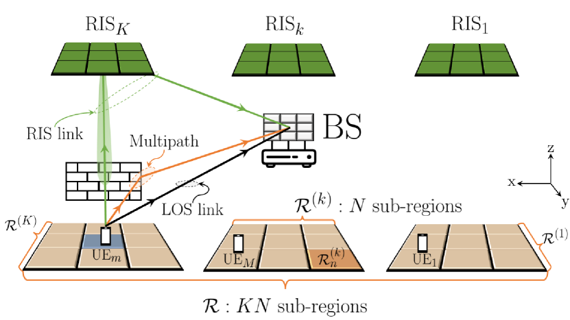
Figure 1 illustrates the considered setup. There is a stationary BS equipped with a uniform planar array (UPA) of elements. The BS is wall-mounted on the x-z plane, at point , i.e., with an antenna spacing of , across both dimensions. There are single antenna UEs that need to be detected and tracked, with unknown positions , where is a 3-dimensional region. The number of UEs, , is not known to the BS. There are fixed RISs aiding the process of detection and tracking. Each RIS is located at a fixed position, , known to the BS, equipped with sub-wavelength elements, arranged to form a UPA with an element spacing of . The RISs are ceiling-mounted on the x-y plane, i.e., , each of which is designed to assist the detection of UEs in a smaller region, . Each RIS element introduces a controllable phase shift, which may vary across the transmitted frames. The element reconfiguration is predefined and stored in . The scalar RIS response for an incident signal, observed at is
| (1) |
where is the angle of arrival (AoA) of the incident signal in azimuth and elevation relative to the RIS’s normal, is the distance to the signal source, relative to the RIS reference point, is the angle of departure (AoD) towards the BS in azimuth and elevation relative to the RIS’s normal, is the fixed and known distance between the RIS’s and BS’s reference points and is the RIS’s NF steering vector.
II-A Detection Procedure
The process for the UE detection is summarised in Algorithm 1. The BS broadcasts a reference signal to trigger the beginning of the detection phase and the UEs initiate their transmissions. A structured channel access allows the BS to distinguish UEs and individually localize them. The available bandwidth (BW) and timeslots create orthogonal pilots, , of timeslots for subcarriers, with and a subcarier spacing of . The pilots are also referred to as resource blocks (RBs). Each UE autonomously and randomly picks a pilot sequence from a pre-determined set, leading to possible collisions. If a UE has already been detected, a dedicated RB is assigned by the BS, for a reliable, collision-free localization procedure.
The pilots are split in two disjoint sets: the set of pilots to be randomly picked by undetected UEs, of cardinality , and the set of pilots assigned by the BS, of cardinality , with . During the detection phase, the UEs transmit OFDM frames using their respective pilots, where the initial frames are used during the signal processing phase to separate the RIS-assisted link and the subsequent frames aid the UE detection and tracking. During the transmitted frames, each RIS uses configurations either designed to scan , or to follow the trajectory of previously identified UEs. The pilot assignment among detected UEs and the RISs’ configurations are distributed by the BS during the adaptive phase. The process is iterated times, considered by the network designer, until no further UEs are detected or the localization accuracy is satisfying.
-
•
The active UEs transmit frames.
-
•
The RISs load reconfigurations.
-
•
The BS separates the static and the non-static signal components.
-
•
filters matched to the RISs’ positions track received energy over different transmissions.
-
•
RIS designed to inspect specific area Received energy indicates UE activity in specific area.
-
•
The BS assigns pilots to the detected UEs.
-
•
The BS provides reconfigurations to the RISs.
II-B Channel & Signal Model
The channel consists of 2 main components; the static and the non-static ones. The static component of the channel refers to all links that remain non-varying for the duration of a single detection phase and encapsulates both the line-of-sight (LOS) link, , with the BS and the multipath, , generated by an unknown number of scatterers. The LOS link between the BS and the UE, for the subcarrier, is given by
| (2) |
for , and , where the scalar is the channel’s complex amplitude and the vector is the BS’s steering vector for an NF source. The complex amplitude is
| (3) | ||||
The scalar indicates whether there is a LOS link with the BS, is the wavelength, , is the speed of light, is the UE’s signal AoA at the BS and is a uniformly distributed random variable, accounting for the synchronization mismatch.
Similarly, the first order reflections are considered and the multipath channel is
| (4) |
where is a random complex vector and the channel’s complex amplitude is given by
| (5) |
where is a complex reflection coefficient, giving the ratio between the multipath and LOS path loss.
Finally, the non-static component, , refers to all links between the UE and the BS via the RISs, as they vary in time with each RIS configuration. For the subcarrier, is modeled as
| (6) | ||||
where the complex scalar is
| (7) | ||||
The scalar indicates whether there is a LOS link between the corresponding UE and RIS, , , is the AoA at the RIS from the corresponding UE, is the fixed AoD from the RIS towards the BS and is the RIS’s reflection known AoA at the BS. Note that is non-static, as it varies for the OFDM frames due to different RIS configurations.
The received signal during the OFDM frame for the subcarrier is organized in a matrix
| (8) |
for , and , where is the transmit power per symbol, and is a circularly-symmetric Gaussian vector with covariance matrix , accounting for the added noise.
III UE detection
In this section, we explore the core idea employed for the detection of UEs; exploiting the energy fluctuations of the non-static signal component over different frames. The RIS-assisted link may be designed to produce a combination of frames that depend on the static channel exclusively and remove the non-static signal components, i.e., the RISs’ configurations. The transmitted pilots can be designed such that there is an where
| (9) | ||||
The procedure to make such a design is not trivial. The coherence time of the channel, the cost of having multiple transmissions and the overall desired application are some of the factors that may shape the RIS design process. Here, we consider that frames are transmitted separately for this procedure. However, this is not a necessity, and is a strategy to simplify notations. The frames designed to assist with the signal extraction may need to be part of a more complex transmission procedure. A thorough investigation of the pilot design and transmission strategy that achieves (9) is left for future consideration. Considering the case with , a simple design is to set and
| (10) |
Thus, for , the non-static component of the signal may be isolated, using
| (11) |
The energy received via the RIS’s reflection changes over time, as the RIS uses different configurations. The combination of all RISs’ contributions in (11) can be plugged into
| (12) |
for , and . The output of (12) is essentially a filter matched to the known location of the RIS for each individual RB and it may act as an energy detector, producing a total of sequences of length . The filter’s output, is connected with the region inspected by the RIS. If we assume that
| (13) | ||||
which depends on the RIS deployment and the RIS design, then the output of the filter in (12) is
| (14) |
which tracks how much energy is reflected by the RIS over the OFDM frames. If is designed to focus in , then the energy detector
| (15) |
indicates the presence of a UE, , within the inspected region, , using the available pilot. In (15), if the received energy exceeds the set thresehold , hypothesis where there is a UE in is assumed to be true. Otherwise, the null hypothesis, , of no present UEs is true.
IV RIS Deployment & Design
In this section, we highlight the degrees of freedom provided by RISs for localization applications. The BS is required to inspect the whole region, which restricts its placement. The deployment of the RISs is, in general, not bound to the same restrictions. Having the RISs to cover a smaller region enables us to consider ceiling mounted RISs, where the inspection of the x-y plane depends on the azimuth and elevation angular resolution of the surface. In contrast, the wall mounted BS requires a high ranging resolution. Each RIS needs to inspect its respective region, , which is divided into sub-regions. The number of sub-regions dictates the number of OFDM transmissions by the UEs, as each sub-region requires a specific configuration for proper inspection. The size of the sub-region dictates the angular resolution required.
Table I shows the considered geometry and the required number of elements and BW, for different sub-region sizes (see Section VI for detailed comparison between the cases with and without RISs). Our proposed detection algorithm has low complexity, but requires an inspection resolution fit for the considered geometry. In particular, there are sub-regions and each one requires iterations of (12) for each possible pilot. Comparing the RIS-enabled system to the one without RISs is not trivial, as the two scenarios may have different requirements, since different inspection techniques require different resources and deployment restrictions may place the BS in a disadvantage. Range-based inspection requires large channel BW, that may be practically infeasible. In other words, the deployment of RISs can lead to resource efficient detection and localization techniques. Moreover, placing the RISs on the ceiling, increases the probability that there will be no obstructions between the UEs and the RIS(s) above them, while the BS-RIS link is assumed to have a strong LOS link by design. The RIS response for each sub-region needs to reflect as much energy as possible for each , i.e.,
| (16) |
Algorithm 2 may be employed for the non-convex optimization problem in (16). Here the core idea is to maximize the RIS response in discrete points within the considered sub-region. For each RIS and each sub-region, the effect of each individual RIS element is optimized until the RIS converges to a specific configuration. The energy reflected for each is not taken into account here.
| Considered Region: | |
|---|---|
| RIS Requirements : cm | ||
|---|---|---|
| Azimuth | ||
| Elevation | ||
| BS Requirements : cm | ||
| Azimuth | ||
| Range | BW GHz | |
| BS Requirements : m | ||
| Azimuth | ||
| Range | BW MHz | |
V Channel Access & Detection
In this section, we examine, in closed-form expressions, the effect of channel collisions in UE detection. As the undetected UEs access the channel randomly, i.e., they use a random RB, the number of UEs that access an RB essentially follows a binomial distribution. The probability that UEs share access of the same RB is given by
| (17) |
for , where and are the total number of active UEs and the number of RBs available.
The probability that a UE can be detected depends on the RB congestion and the transmit power. A UE can be detected if total UEs transmit with over RBs with a probability of
| (18) | ||||
where denotes the probability of detection when UEs share a single RB and it depends, among other factors, on the considered geometry. Therefore, the probability that UEs are detected is
| (19) | ||||
If we assume no newly active UEs and the procedure is repeated over multiple detection phases, say , the number of UEs that access the channel randomly may decrease, using an adaptive allocation strategy, i.e., the BS may assign specific RBs to detected UEs. Assuming that the transmit power and the number of available pilots remain constant, we derive the simpler notation to mark the probability that out of undetected UEs are detected during the detection phase. After phases, the discrete probability distribution of the total number of detected UEs is given by
| (20) |
for , where the vector gives the probability of new UEs being detected and it is given by
| (21) |
with denoting the probability distribution of the previous phase and the matrix
| (22) |
accounts for different probability distributions for new UEs being detected, based on the total number of undetected UEs. The initial distribution () is simply
| (23) |
VI Simulation Results
| Simulation Parameters | |||||
|---|---|---|---|---|---|
| 6 GHz | 15 KHz | 1 | |||
| 34 | 6 | ||||
| 24 | 24 | ||||
| BW | 15 KHz | 1 | 5 | ||
| 100 | 10 dB | -174 dBm/Hz | |||
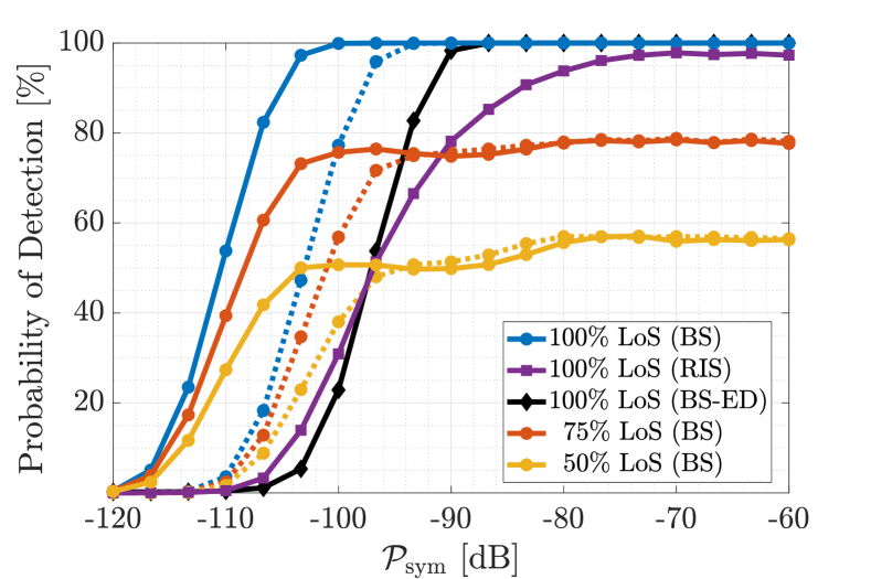
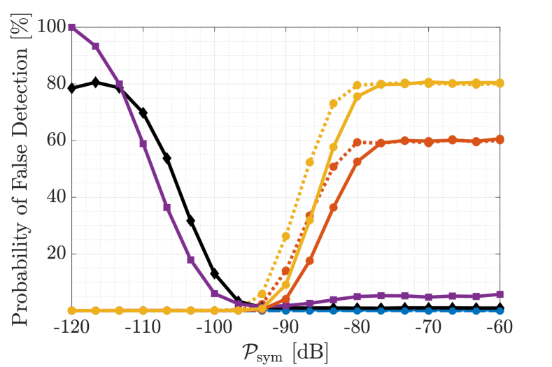
Figure 2 compares the performance of a system operating with or without RISs, for a single active UE. As illustrated in Table I, the BS requires a significantly larger channel BW to achieve the same inspection resolution as in the cases with RISs. The total channel BW for the BS inspection is set to GHz ( MHz), as opposed to the case with RISs in Table II, where a single subcarrier is needed (BW = KHz). The dotted lines indicate stronger multipath (). As the LOS probability and the multipath level (dotted lines) vary, the simulations show that a strong LOS is imperial for the performance of such a system, as the probability of detection experiences saturation and the probability of false detection rises significantly. For perfect LOS conditions, the BS inspection seems to outperform the RIS-based system due to the stronger direct link. However, this is at the cost of significantly larger BW for the cases without RISs.
If the BW is not increased, the UE detection may be reduced to a standard energy detection (ED) problem, as considered in [3] (solid black line in Fig. 2), i.e., there is no RIS and no position information is extracted. In such a scheme, UE collisions may be handled with joint channel estimation. It is shown that introducing the RISs can augment the UE detection to spatially aware detection, without degrading the detection performance.
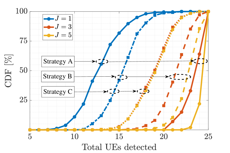
Figure 3 shows the cumulative distribution function (CDF) for the number of detected UEs, for different numbers of detection phases and for different channel access strategies. There are 25 active UEs and 25 available RBs. Strategy A refers to a separate set of RBs reserved for the detected UEs (). Strategy B refers to random channel access for each detection phase, without separating the detected and the undetected UEs (). Strategy C is similar to B, but the UEs use a single pilot for all detection phases. It is clear that multiple detection phases lead to more detected UEs. Strategies B and C have RBs for the random access, making them more effective when the detection procedure is performed only once. Note that for a single detection phase, Strategies B and C are essentially the same. However, for multiple iterations of the detection procedure Strategy A outperforms Strategies B and C, since the detected UEs no longer interfere with the undetected ones. Comparing Strategies B and C, it is evident that accessing different random channels is more effective. In general, multiple iterations over different RBs provide a more favourable detection environment.
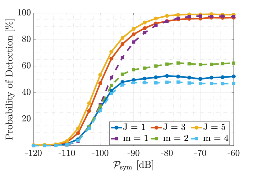
Figure 4 shows the probability of detection for different number of detection phases and different number of UEs in a single RB (channel congestion level). Here strategy A is considered, with total UEs. When multiple UEs access an RB during a detection phase (), (dashed lines) experiences saturation. In this case, we can not expect reliable detection due to inter user interference (ISI). Channel congestion is more prominent when a single phase is considered. The probability of detection is limited by the saturation of , as (18) indicates. Strategy A over multiple phases allows for a structured channel access and the probability of channel congestion decreases.
VII Conclusions
We have proposed an iterative algorithm for detection/localization of an unknown number of UEs. We have shown that the proposed iterative detection process allows the BS to control the allocation of resources for the detected UEs, and increases the probability of detection. Moreover, we have shown that the restrictions on the BS placement for specific geometrical configurations lead to infeasible requirements for proper inspection, while the presence of RISs reduces the required BW significantly, and improves the localization/detection performance by bypassing blockages and providing a second view on the UEs.
References
- [1] Q. Zhang, J. Zhang, and S. Jin, “Grant-free random access in cell-free massive MIMO systems with UE detection thresholds: A stochastic geometry approach,” IEEE Trans. Veh. Technol., vol. 72, no. 6, pp. 8117–8121, June 2022.
- [2] M. Guo and M. C. Gursoy, “Joint activity detection and channel estimation in cell-free massive MIMO networks with massive connectivity,” IEEE Trans Commun, vol. 70, no. 1, pp. 317–331, January 2022.
- [3] T. Li, Y. Wu, M. Zheng, W. Zhang, C. Xing, J. An, X.-G. Xia, and C. Xiao, “Joint device detection, channel estimation, and data decoding with collision resolution for MIMO massive unsourced random access,” IEEE J. Sel. Areas Commun., vol. 40, no. 5, pp. 1535–1555, May 2022.
- [4] X. Meng, F. Liu, S. Lu, S. P. Chepuri, and C. Masouros, “RIS-assisted integrated sensing and communications: A subspace rotation approach,” arXiv preprint arXiv:2210.13987, May 2022.
- [5] S. Buzzi, E. Grossi, M. Lops, and L. Venturino, “Radar target detection aided by reconfigurable intelligent surfaces,” IEEE Signal Process. Lett., vol. 28, pp. 1315–1319, June 2021.
- [6] M. Rihan, E. Grossi, L. Venturino, and S. Buzzi, “Spatial diversity in radar detection via active reconfigurable intelligent surfaces,” IEEE Signal Process. Lett., vol. 29, pp. 1242–1246, May 2022.
- [7] D. Dardari, N. Decarli, A. Guerra, and F. Guidi, “LOS/NLOS near-field localization with a large reconfigurable intelligent surface,” IEEE Trans. Wireless Commun., vol. 21, no. 6, pp. 4282–4294, June 2021.
- [8] G. Mylonopoulos, C. D’Andrea, and S. Buzzi, “Active reconfigurable intelligent surfaces for user localization in mmwave MIMO systems,” in Proc. IEEE SPAWC’22, pp. 1–5, July 2022.
- [9] G. Mylonopoulos, L. Venturino, S. Buzzi, and C. D’Andrea, “Maximum-likelihood user localization in active-RIS empowered mmwave wireless networks,” in Proc. IEEE EuCAP’2023, pp. 1–5, March 2023.
- [10] F. Laue, V. Jamali, and R. Schober, “IRS-assisted active device detection,” in Proc. IEEE SPAWC’21, pp. 556–560, September 2021.
- [11] F. Laue, V. Jamali, and R. Schober, “RIS assisted device activity detection with statistical channel state information,” arXiv preprint arXiv:2206.06805, May 2022.