On point-ahead angle control strategies for TianQin
Abstract
Pointing-related displacement noises are crucial in space-based gravitational wave detectors, where point-ahead angle control of transmitted laser beams may contribute significantly. For TianQin that features a geocentric concept, the circular high orbit design with a nearly fixed constellation plane gives rise to small variations of the point-ahead angles within nrad in-plane and nrad off-plane, in addition to a static bias of 23 rad predominantly within the constellation plane. Accordingly, TianQin may adopt fixed-value compensation for the point-ahead angles and absorb the small and slow variations into the pointing biases. To assess the in-principle feasibility, the far-field tilt-to-length (TTL) coupling effect is discussed, and preliminary requirements on far-field wavefront quality are derived, which have taken into account of TTL noise subtraction capability in post processing. The proposed strategy has benefits in simplifying the interferometry design, payload operation, and TTL noise mitigation for TianQin.
I Introduction
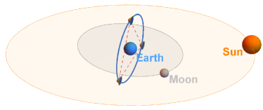
TianQin is a proposed space-based gravitational-wave (GW) detection mission to operate in high Earth orbits [1]. The detector consists of three identical drag-free controlled satellites to form a nominal equilateral triangle with an armlength of km (see Fig. 1). The mission design also features a nearly fixed constellation plane (hence the detector pointing also fixed) that is set almost perpendicular to the ecliptic plane. Heterodyne laser interferometric links are to be established between free-falling test masses (TMs) inside different satellites to monitor picometer-level armlength changes in the frequency band of 0.1 mHz–1 Hz.
A forerunner in space-based GW detection is the LISA mission [2], which uses heliocentric orbits trailing or leading the Earth by , and has an armlength of km. By a special arrangement of the orbits, the plane of the triangular constellation can revolve around the Sun and form a angle relative to the sunlight, providing a stable thermal environment for the three spacecraft. Moreover, the variable detector pointing may also help improve the sky localization of GW sources.
The payload design of LISA has put forward that every spacecraft carries two Movable Optical Sub-Assemblies (MOSAs), each consisting of a telescope, an optical bench, and an inertial sensor, rigidly connected to one another by supporting structures [3]. The TM inside the inertial sensor is kept free-floating along the interferometry arm and suspended in other degrees of freedom by electrostatic forces. The entire MOSAs can rotate in the constellation plane via tracking mechanisms to correct for the internal angle variation () of the triangle due to orbital dynamics. Meanwhile, the Drag-free and Attitude Control (DFAC) of the spacecraft is responsible for tracking the pointing variation orthogonal to the constellation plane with micro-Newton thrusters [4]. The applicability of such a payload architecture and control strategy to TianQin has been studied, and an adaptation to the geocentric orbits can be made [5].
Accurate pointing of outgoing laser beams at distant spacecraft is crucial for both LISA and TianQin since pointing errors can have a major impact on the precision of the TM-to-TM displacement measurement. Estimated pointing requirements are nrad in DC bias and nrad/Hz1/2 in jitters [2], which push the boundary of the current state of the art. Given the MOSA configuration and the involvement of DFAC, the issue of fine-pointing should also be dealt with on the system level.
Due to finite light travel time, a complication in pointing control arises where a certain amount of leading ahead is needed for the transmitted beams to compensate for the lateral motion of the remote satellite relative to the line of sight. The point-ahead angle (PAA) refers to the angle between the received and transmitted beams [6], which can be decomposed into in-plane and off-plane components when projecting onto the constellation plane. The values of PAA can be fully determined by the orbits and must be taken into account in formulating pointing control strategies to meet the stringent requirements.
The constellation plane of LISA features yearly variation around the Sun, and when combined with the cartwheel motion of the triangle, it gives rise to an off-plane PAA variation of rad about the nearly zero mean over the course of one year, as well as an in-plane bias of rad with nrad variation [7]. The comparatively large off-plane variation necessitates a dedicated PAA mechanism on the optical bench for in-orbit compensation in either open-loop or closed-loop manners [8]. Since the mechanism is located in the optical path of the outgoing laser beam, it has to meet strict requirements on path-length and angular stabilities [9], which may also be monitored by a dedicated interferometer on the optical bench [10].
As hinted earlier, an important issue faced by PAA control is the tilt-to-length (TTL) coupling, which refers to the effect that jitters of the satellites and MOSAs can induce displacement noise in the longitudinal interferometric measurements between two TMs. For small jitters near a given angle, the effect can be modeled to the first order by a linear relationship via a set of coupling coefficients (TTL factors) [11]. Due to inevitable misalignment and imperfection of optical components and pointing offsets of laser beams, it is highly challenging to reduce the coupling coefficients to desired small values in hardware, and therefore dedicated TTL factor estimation and noise subtraction in post-processing seem necessary in the current measurement scheme [11, 12, 13, 14]. Unfortunately for various reasons, PAA adjustments are expected to change the TTL factors [7, 15]. The temporal variability complicates the estimation processes of the TTL factors, which generally require sufficiently long windows of data streams to reach the desired accuracy [7, 14]. To tackle the issue, an open-loop control strategy for discrete PAA corrections has been proposed for LISA [7] which maximizes intervals between adjustments through coordination of the six optical benches. Nevertheless, more studies appear to be needed to demonstrate realistically the impact of PAA adjustments on the system performance and the quality of data products.
Regarding TianQin, the situation is different, as we will show that the PAA variation is rather small owing to its geocentric co-planar orbit design with a nearly fixed constellation plane in the inertial space (Sec. II). Therefore, it motivates us to pursue a different PAA control strategy, where only the static bias is compensated. To examine its feasibility, we analyze the far-field TTL effect due to the uncorrected PAA variation and discuss possible countermeasures (Sec. III). In addition, a few prominent aspects of implementation are commented (Sec. IV). We expect that the strategy can help circumvent potential difficulties in TTL mitigation with time-variable coupling coefficients due to PAA adjustments.
II TianQin’s orbits and point-ahead angles
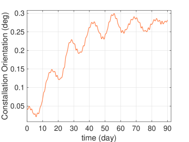
One can calculate the PAA evolution from the orbits. A set of optimized initial orbital elements is given in Table 1 [16], taking account of lunisolar perturbation and the non-spherical gravity of the Earth. Assuming pure gravity flight under drag-free control, the ensuing orbital evolution fulfills the constellation stability requirements, e.g., the breathing angle variation within . Owing to the high altitude, the constellation plane is nearly fixed with only a small variation of per orbit (3.6 days, see Fig. 3).
| SC1 | SC2 | SC3 | |
|---|---|---|---|
| (km) | 99995.572323 | 100011.400095 | 99993.041899 |
| 0.000430 | 0.000000 | 0.000306 | |
| 94.697997 | 94.704363 | 94.709747 | |
| 210.445892 | 210.440199 | 210.444582 | |
| 358.624463 | 0.000000 | 0.001624 | |
| 61.329603 | 179.930706 | 299.912164 |
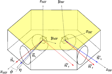
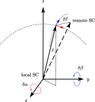
Directions of transmitted beams and PAAs can be described in the MOSA frames (MF), as illustrated in Fig. 4. The origin of a MOSA frame is at the geometric center of the electrode housing of the TM, which coincides with the TM’s center of mass (CoM) in the nominal state. The MOSA axis () is aligned with the received beam, which is realized by nulling the differential wavefront sensing (DWS) signal. The DWS measures the pitch and yaw angles between the wavefronts of the local reference beam and the received beam using quadruple photodiodes, and provides the input for the pointing/attitude control. The two MOSA axes aligned with the two received beams define what we call the local constellation plane. Then the -axis is defined to be in the plane (see Fig. 4) and point to the adjacent MOSA, so that the direction of the transmitted beam can be uniquely specified with respect to the received beam. Thereby PAAs can be decomposed into in-plane and off-plane components. In calculating PAAs, we neglect the separation of the TM’s CoM from the satellite’s CoM ( m), given the huge armlength of TianQin.
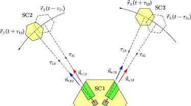
The situation of PAAs is further illustrated in Fig. 5, where the vector represents the direction of the beam from SC to SC (), and represents the opposite direction of the beam from SC to SC. Therefore the PAA can be defined as the angle between and . The propagation time for the beam traveling from SC to SC can be determined from
| (1) |
and similarly for from
| (2) |
where is the light speed and we have neglected the general relativistic effect. Solving these implicit equations iteratively yields and , and hence and can be calculated. We use PAAij to denote the PAA of SC with respect to SC and use and to denote the in-plane and off-plane PAAs, respectively. Utilizing simulated TianQin orbit data, the PAA evolutions of SC1 during a 3-month observation period are computed and shown in Fig. 6.
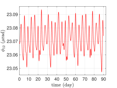
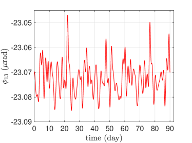
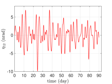
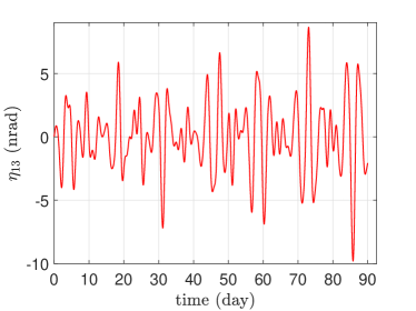
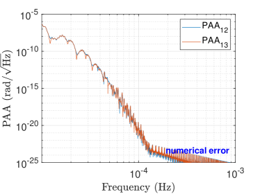
In Fig. 6, the off-plane PAAs of TianQin are characterized by fluctuations centering at 0 with a range of nrad, while the in-plane components oscillate around +23.07 rad or rad with a range of nrad. The PAA variations are quite small compared to the divergence angle of the outgoing beam (rad), which suggests that the remote satellite can still receive sufficient laser intensity even with a fixed PAA. Furthermore, Fig. 7 reveals that the PAA is slowly varying, and has negligible contribution to pointing jitters in the detection band.
III Proposed strategy and far-field TTL effect
Regarding TianQin’s PAA control, since the variation is quite small, we envision a fixed offset compensation without active real-time adjustment at least in the science mode. Therefore, one needs to absorb the small and slow PAA variations ( nrad) into the pointing biases (10 nrad DC) of the laser beams. Given increased total pointing biases (up to nrad), the requirement on the far-field wavefront quality becomes more stringent in order to keep the coupling noise of the wavefront error and pointing jitters at roughly the same level [17]. In this section, we analyze this far-field TTL effect and estimate corresponding requirements.
III.1 Gaussian beam model
Implementing the static compensation strategy of PAAs makes the optical field of the transmitted beam stationary relative to the transmitting MOSA. However, it introduces extra motion of the receiving satellite relative to the distant optical field. In other words, the remote satellite may swing back and forth in the field of view of the emitting satellite. This relative motion due to uncompensated PAA may induce an additional TTL effect. To analyze the impact, a simulation is conducted to track the positions of SC2 and SC3 with respect to the transmitted beams from SC1 during one 3-month observation period.
To describe the motion of the remote satellite relative to the transmitted beam, we introduce the beam frame (BF). As depicted in Fig. 4, the -axis is the transmitted beam direction with a fixed PAA relative to the incoming beam direction, and the -axis is aligned with the plane containing both received and transmitted directional vectors (, ), and the -axis follows the right-hand rule.
For an initial setup, the laser field between two satellites is modeled by an ideal Gaussian beam propagating along the -axis. Due to the rotational symmetry about , we use the cylindrical coordinates instead. The electric component of the Gaussian beam with the waist at the origin is given by
| (3) |
where gives the beam radius, and denotes the Gouy phase shift, and the wavefront curvature reads . Moreover, is the wave number with the wavelength nm, and is the angular frequency. The quantity is the Rayleigh range [18], and for TianQin, we have the waist radius cm. The flight time taken by the wavefront emitted from the waist to reach the point is denoted by , which can be derived from the phase term of Eq. (3) as
| (4) |
The wavefront is emitted at and reaches the remote satellite at . The position of the remote satellite at in the beam frame at can be expressed as . The relation between and is determined by
| (5) |
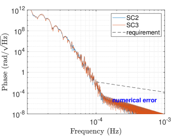
which allows us to solve for given each by iteration, and vice versa. Subsequently, the received phase at the remote satellite can be computed. The Fig. 8 shows that the received phase fluctuation due to the static PAA compensation predominantly distributes below Hz due to the orbital dynamics, and that the impact is considerably lower than TianQin’s requirement in the case of Gaussian beams. The ASD result is consistent with the estimated Doppler effect due to luni-solar gravitational perturbation [19, 20].
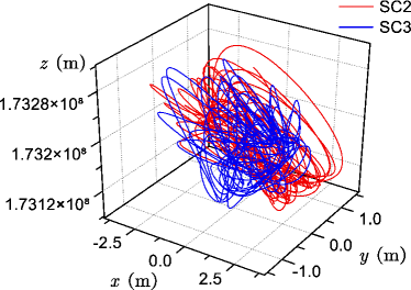
Additionally, we can obtain the trace of the remote satellite in the beam frame (see Fig. 9), and the lateral satellite motion due to uncompensated PAAs is only of a few meters in the - plane. Based on this initial model, we can further substitute the ideal Gaussian beam with distorted Gaussian beams in the beam frame and analyze the resulting far-field TTL effect.
III.2 Effect of far-field wavefront error
Previous studies have revealed that the wavefront of an emitted beam is not ideally spherical but distorted in reality, which leads to additional phase noise at the receiving satellite when combined with pointing jitters of the emitting beam (see, e.g., [17, 21, 22, 23, 24]). Various factors including aberration in the optical system contribute to this phase deviation which is denoted by . Thereby we model the far-field phase by a scalar field in Cartesian coordinates, i.e.
| (6) |
where we have dropped the time-dependent term . The displacement noise induced by pointing jitters can be approximated by
| (7) |
where is the phase gradient and is the relative displacement of the remote satellite in the beam frame due to jitters (see Fig. 11). Given the remote satellite position , the displacement can be expressed as
| (8) |
where and represent the angular jitters around the -axis (pitch) and the -axis (yaw), respectively. The wavefront error is expected to have a rather weak dependence on at the far field, and hence we neglect the term . Substituting Eq. (8) into Eq. (7), the TTL factors along two orthogonal directions can be obtained as
| (9) |
and
| (10) |
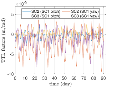
On the right hand sides of the above equations, the first terms represent the TTL factors due to the wavefront distortion , and the second terms are due to the Gaussian wavefront. Because the Gaussian contribution (see Fig. 10) is significantly lower than the requirement of m/rad, we can neglect the second terms in the subsequent analysis.
In the current measurement scheme, the TTL effect can be calibrated and subtracted from the science data in post-processing (see, e.g., [12]). This can help alleviate the requirements on the far-field wavefront quality. Assuming a conservative capability of subtracting the TTL noise to a residual level of ( in [12] estimated for LISA), the requirement on the TTL factors can be relaxed by five times to m/rad ( pm/nrad).
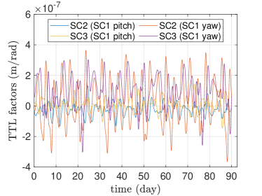
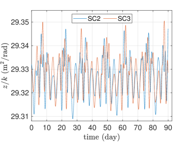
In Eqs. (9, 10), the TTL factors are expressed as the products of the coefficient and the partial derivatives and . From the remote satellite traces shown in Fig. 9, the coefficient can be calculated as a function of time (see Fig. 12). The maximum value of is found to be less than 29.36 m2/rad, and it implies that the partial derivatives of the wavefront deviation and at far field should be maintained below rad/m.
To help confirm the far-field wavefront requirement derived from Eqs. (9, 10), we take the defocused Gaussian beam as an example. Defocus is one of the main contributors to far-field wavefront distortion through diffraction. From [25, 6], in the case of defocus only, the corresponding phase noise can be expressed as
| (11) |
where denotes the wavefront error at the exit pupil, and denotes the telescope diameter (30 cm for TianQin). Moreover, the total pointing error can be decomposed into the bias (DC and out-of-band slow-varying components) and the in-band fluctuation .
In the case of TianQin, when considering the uncompensated residual PAA (25 nrad) and the DC pointing bias (10 nrad), can attain a maximum value of 35 nrad. To fulfill TianQin’s allocated budget (1 pm/Hz1/2 before post-processing), the acceptable local wavefront error of the transmitted beam is estimated to be according to Eq. (11). Adding this aberration to the transmitted Gaussian beam, we can obtain an analytical expression of based on the method of [26]:
| (12) |
Hence we estimate the maximum partial derivatives . This is consistent with the requirement of rad/m derived from Eqs. (9, 10) in previous paragraphs. Additionally, Fig. 13 shows the corresponding TTL factors throughout one 3-month observation window using the satellite traces of Fig. 9, which fall below m/rad requirement. Unfortunately, the analysis for general cases with other types of aberrations becomes much more complicated. This is deferred to future works.
IV Concluding Remarks
In the paper, we have proposed for TianQin a fixed offset compensation strategy for PAAs based on the characteristics of TianQin’s geocentric orbits. Moreover, we discuss related effect of the far-field wavefront errors for TianQin, and a corresponding requirement of rad/m is derived on the spatial derivatives of the far-field phase deviation from ideal Gaussian beams (see Eq. (6)). The analysis gives a preliminary green light for the proposed strategy. Regarding the future implementation, two points deserve to be mentioned.
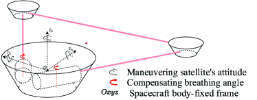
First, since the TianQin satellites will be installed with single-side flat-top sun shields which must be illuminated by the Sun [27, 28, 29], it requires that the three satellites perform a flip maneuver in attitude after each 3-month observation window. The maneuver interchanges the positions of the two MOSAs with respect to the normal of the constellation plane, hence flipping the parities of the PAA offsets as well. Therefore, the optical bench and telescope design should take into account these two scenarios, and be capable of switching between the two PAA pointing states.
Second, TianQin has proposed a 3+3 month observation scheme in its operation [1]. To reduce the time spent on re-establishing laser links before each observation window or from accidental link losses, one option is to have a steering mirror performing the dual roles of fast link acquisition (see, e.g., [30]) and PAA compensation. This means that once the scanning and acquisition phase is complete, the actuated mirror should switch to static PAA compensation. Then the process involves one transferring the pointing authority of the transmitted laser beam from the steering mirror to the DFAC and MOSA tracking control when the DWS signals become available, i.e., from in-field pointing to telescope pointing. During this process, the mirror can be controlled to gradually settle to a fixed angle for PAA offset in the science mode.
Since the pointing of the outgoing beam is static relative to the telescope and optical bench, barring small residual jitters from the mirror mechanism, some implications of the proposed PAA control scheme are the following. First, it may help ease the telescope design regarding the far-field wavefront error due to very small fields of view ( nrad) required for the transmitted beams in the science mode. Second, it may render the total TTL factors less varying, and hence alleviating potential complexity in TTL estimation, and reducing possible data quality degradation due to PAA adjustments. More details are deferred to future works.
Acknowledgements.
The authors thank Yuzhou Fang, Qing Xiao, Fan Zhu, Bobing Ye, Hsien-Chi Yeh, and Jun Luo for helpful discussions and comments. X. Z. is supported by the National Key R&D Program of China (Grant Nos. 2022YFC2204600 and 2020YFC2201202) and NSFC (Grant No. 12373116), and Fundamental Research Funds for the Central Universities, Sun Yat-sen University (Grant No. 23lgcxqt001).References
- J. Luo et al. [2016] J. Luo et al., TianQin: a space-borne gravitational wave detector, Class. Quantum Grav. 33, 035010 (2016).
- LIS [2017] LISA Laser Interferometer Space Antenna, A proposal in response to the ESA call for L3 mission concepts, arXiv:1702.00786 (2017).
- Weise et al. [2017] D. Weise, C. Braxmaier, P. Gath, H. R. Schulte, and U. Johann, Optical metrology subsystem of the LISA gravitational wave detector, in International Conference on Space Optics—ICSO 2006, Vol. 10567 (SPIE, 2017).
- Faulks et al. [2000] H. Faulks et al., Study of the laser interferometer space antenna final technical report, ESTEC Contract (2000).
- Fang et al. [2024] Y. Fang, X. Zhang, F. Fu, and H. Li, On payload architecture and pointing control strategies for TianQin (2024), accepted by Phys. Rev. D.
- Bender et al. [1998] P. Bender, A. Brillet, I. Ciufolini, A. Cruise, C. Cutler, K. Danzmann, F. Fidecaro, W. Folkner, J. Hough, P. McNamara, et al., LISA Pre-Phase A Report, Max-Planck-Institut für Quantenoptik, Garching (1998).
- Houba et al. [2022a] N. Houba, S. Delchambre, T. Ziegler, G. Hechenblaikner, and W. Fichter, LISA Point-Ahead Angle Control for Optimal Tilt-to-Length Noise Estimation (2022a), arXiv:2208.11033 [physics.ins-det] .
- Danzmann et al. [2011] K. Danzmann, T. Prince, et al., LISA assessment study report (Yellow Book), Technical Report (2011).
- Henein et al. [2009] S. Henein, P. Spanoudakis, P. Schwab, I. Kjelberg, L. Giriens, Y. Welte, L. Dassa, R. Greger, and U. Langer, Design and development of the point-ahead angle mechanism for the laser interferometer space antenna (LISA), in Proceedings of the 13th European Space Mechanisms & Tribology Symposium, Vienna, Austria (Citeseer, 2009).
- Jennrich [2009] O. Jennrich, LISA technology and instrumentation, Class. Quantum Grav. 26, 153001 (2009).
- Houba et al. [2022b] N. Houba, S. Delchambre, T. Ziegler, and W. Fichter, Optimal Estimation of Tilt-to-Length Noise for Spaceborne Gravitational-Wave Observatories, Journal of Guidance, Control, and Dynamics 45, 1078 (2022b).
- Paczkowski et al. [2022] S. Paczkowski, R. Giusteri, M. Hewitson, N. Karnesis, E. D. Fitzsimons, G. Wanner, and G. Heinzel, Postprocessing subtraction of tilt-to-length noise in LISA, Phys. Rev. D 106, 042005 (2022).
- Houba et al. [2023] N. Houba, S. Delchambre, G. Hechenblaikner, T. Ziegler, and W. Fichter, Time-delay interferometry infinity for tilt-to-length noise estimation in LISA, Class. Quantum Grav. 40, 107001 (2023).
- George et al. [2023] D. George, J. Sanjuan, P. Fulda, and G. Mueller, Calculating the precision of tilt-to-length coupling estimation and noise subtraction in LISA using Fisher information, Phys. Rev. D 107, 022005 (2023).
- Hasselmann et al. [2021] N. F. Hasselmann, C. Brugger, T. Vogel, E. D. Fitzsimsons, U. Johann, G. Heinzel, D. Weise, and A. Sell, LISA optical metrology: tilt-to-pathlength coupling effects on the picometer scale, in International Conference on Space Optics — ICSO 2020, Vol. 11852 (SPIE, 2021).
- Ye et al. [2019] B. Ye, X. Zhang, M. Zhou, Y. Wang, H. Yuan, D. Gu, Y. Ding, J. Zhang, J. Mei, and J. Luo, Optimizing orbits for TianQin, Int. J. Mod. Phys. D 28, 1950121 (2019).
- Bender [2005] P. L. Bender, Wavefront distortion and beam pointing for LISA, Class. Quantum Grav. 22, S339 (2005).
- Freise and Strain [2010] A. Freise and K. Strain, Interferometer Techniques for Gravitational-Wave Detection, Living Reviews in Relativity 13, 1 (2010).
- Zhang et al. [2021] X. Zhang, C. Luo, L. Jiao, B. Ye, H. Yuan, L. Cai, D. Gu, J. Mei, and J. Luo, Effect of Earth-Moon’s gravity on TianQin’s range acceleration noise, Phys. Rev. D 103, 062001 (2021).
- Zheng et al. [2023] L. Zheng, S. Yang, and X. Zhang, Doppler effect in TianQin time-delay interferometry, Phys. Rev. D 108, 022001 (2023).
- Sasso et al. [2018] C. P. Sasso, G. Mana, and S. Mottini, Coupling of wavefront errors and pointing jitter in the LISA interferometer: misalignment of the interfering wavefronts, Class. Quantum Grav. 35, 245002 (2018).
- Ming et al. [2021] M. Ming, Y. Jiang, J. Zhang, Z. Wang, Q. Xiao, H. Duan, and H.-C. Yeh, Analysis on the coupling effect of wavefront distortion and pointing misalignment in space laser interferometry, Class. Quantum Grav. 38, 195010 (2021).
- Weaver et al. [2022] A. J. Weaver, G. Mueller, and P. J. Fulda, Wavefront error based tilt-to-length noise analysis for the LISA transmitted beam, Class. Quantum Grav. 39, 195016 (2022).
- Xiao et al. [2023] Q. Xiao, H. Duan, M. Ming, J. Zhang, F. Zhu, Y. Jiang, and H.-C. Yeh, The analysis of the far-field phase and the tilt-to-length error contribution in space-based laser interferometry, Class. Quantum Grav. 40, 065009 (2023).
- Robertson et al. [1997] D. I. Robertson, P. McNamara, H. Ward, and J. Hough, Optics for LISA, Class. Quantum Grav. 14, 1575 (1997).
- Winkler [1997] W. Winkler, A truncated Gaussian beam in the far field, Class. Quantum Grav. 14, 1579 (1997).
- Zhang et al. [2018] X. Zhang, H. L. Li, and J. Mei, Thermal stability estimation of TianQin satellites based on LISA-like thermal design concept (2018), internal technical report (in Chinese).
- Chen et al. [2021] H. Chen, C. Ling, and X. Zhang, Thermal environment analysis for TianQin, Class. Quantum Grav. 38, 155015 (2021).
- Wang et al. [2023] D. Wang, X. Zhang, L. Zhang, and M. Li, On long-term thermal stability of TianQin satellites (2023), submitted.
- Hechenblaikner et al. [2023] G. Hechenblaikner, S. Delchambre, and T. Ziegler, Optical link acquisition for the LISA mission with in-field pointing architecture, Optics & Laser Technology 161, 109213 (2023).