Non-Divergent Spinning Substructures Near Acoustic Field Nodes
Abstract
In this work, we examine the extraordinary behavior of polarization and spin angular momentum (AM) density in the vicinity of longitudinal field zeros in three-dimensional monochromatic acoustic fields. We demonstrate that, as governed by the continuity equation, the velocity fields of arbitrary acoustic sources maintain non-diffractive elliptical polarization structures that enclose longitudinal field zeros, despite having divergent transverse spatial profiles of intensity. Furthermore, embedded in these nonparaxial field contours, for infinite distance, are threads of circular polarization singularities. We illuminate these inherent properties in acoustic vortex fields, dipole arrays, and the famous Young’s double slit experiment. Our results reveal novel characteristics of vector sound waves that provide a platform for future studies and applications of structured acoustic waves and chiral acoustic phenomena.
I Introduction
Singularities in complex inhomogeneous scalar and vector wave fields exhibit rich topological characteristics. In classical vector waves, there exists a fundamental property known as polarization, in which an abundance of singular features have been studied extensively, particularly those found in structured monochromatic light [1, 2]. Structured acoustic waves with twisted wave fronts carrying orbital angular momentum were first demonstrated experimentally in Ref. [3]. Recent theoretical and experimental results demonstrate analogous properties of polarization and angular momenta in the longitudinal (curl-free) vector velocity fields of acoustic waves [4, 5, 6, 7, 8, 9], opening an avenue for future applications in acoustic tweezers [10, 11, 12, 13], acoustofluidics [14, 15], underwater communications [16, 17], and biomedical imaging [18, 19, 20].
In paraxial sound, the velocity field vector is approximately collinear with wave vector yielding a homogeneous distribution of linear polarization in space. This constraint is reasonable for distances far from a localized acoustic source, however, in the near-field, all spatial field components are substantial (i.e., nonparaxial in nature). The local rotational field trajectories associated with nonparaxial sound is highly nontrivial [6, 21], and can be described by a dynamical variable known as spin angular momentum (AM) density. Peculiar manifestations of spin AM density arise both in both optics and acoustics, notably, the signature of transverse spin, for example, in evanescent waves [22, 23, 6] and two-wave interference [24].
Threads of polarization singularities, such as lines of strictly circular and linear polarization, are imprinted in vector waves due to the natural occurrence of field zeros. It was shown recently [25] that optical vortex beams possess remarkable and non-intuitive features of non-diffractive polarization near the phase singularities for arbitrary large distances. Moreover, a study found that such polarization and momentum structures exist around any persisting transverse field zero (thread of linear polarization) of electromagnetic radiation and light interference patterns from an arbitrary localized source [26]. Evidently, this general phenomenon of light originates from Maxwell electromagnetism and the stability of electromagnetic nulls in the far-field.
In this text, motivated by these studies [25, 26], we analyze the general properties of polarization and spin near singular imprints of nonparaxial monochromatic acoustic waves. We show that intrinsic field zeros (phase singularities) produce remarkable non-divergent vector characteristics of sound, in direct analogy with features found in light. Indeed, accompanying polarization structures of invariant and stable cross-section formed by the vector velocity fields from a localized acoustic source is persistent lines of polarization singularities. To illustrate these results, we consider nonparaxial, diverging acoustic vortex beams, a wavelength-spaced acoustic dipole array, and Young’s double slit experiment.
While we are aware of the studies demonstrating strong nonlinearity near phase singularities of acoustic fields [27], our present approach is linear, since we consider effects in low-intensity regions in the far field of the interference patterns.
II General Theory
II.1 Background
In this section, we briefly review relevant equations of motion and dynamical properties of acoustic waves. In addition, we discuss acoustic polarization singularities and define a polarization parameter important for analyzing spatial distributions of individual velocity field components.
Let us consider monochromatic acoustic waves of frequency in a homogeneous medium of mass density and compressibility :
| (1) |
where and are the complex scalar pressure and vector velocity fields, respectively. The vector velocity field is longitudinal ( yet in the nonparaxial regime can be generally written in terms of its transverse and longitudinal components: where denotes the unit vector collinear with The degree in which is circularly-polarized is given by the normalized spin AM density
| (2) |
In plane acoustic waves, the spin AM density vanishes, however, inhomogeneous fields produce nonzero spin AM density orthogonal to the polarization ellipse. Moreover, the time-averaged energy density of the acoustic fields is
| (3) |
Note that the transverse spatial extent of energy density naturally diverges with respect to distance from a source, with theoretical exceptions such as Bessel and Airy beams.
In direct analogy to the singular behavior around transverse field zeros of electromagnetic fields, vanishing longitudinal velocity of acoustic waves yields nearby velocity fields that are circularly polarized, i.e., the orientation of the polarization ellipse axes is undefined. Note that lines of circular polarization (commonly referred to as C lines [28, 29]) exist where which is equivalent to the spin condition .
Here, we use a quantity introduced in [25, 26], which we label as the “LT-alignment” parameter
| (4) |
Note that provides a laconic description of the relative longitudinal-to-transverse (LT) field distributions in space, e.g., it follows from Eq. (4) that for we have ; likewise, gives It was shown in [25, 26] for optical vortex beams and general electromagnetic radiation that the contour draws out a non-diffracting tube enclosing a transverse zero (thread of linear polarization) for arbitrary distance. In Section II.2, we demonstrate that a similar effect holds, that is, for any physical source of acoustic waves containing longitudinal field zeroes there exists the contour of invariant elliptical cross section that extends to infinity.
II.2 Formalism
Let us consider far-field acoustic radiation from any localized source, in which the scalar pressure field can be expressed in spherical coordinates in the general form
| (5) |
where is the far-field directivity factor unique to the source geometry. A straightforward derivation from Eq. (1) gives the arbitrary vector velocity field:
| (6) |
where the angular factors and are
| (7) |
Importantly, the radial component has dependence, while the transverse components and have dependence. Albeit, dominates in the far-field, however when (i.e., ), the transverse components are non-neglible, enabling nonparaxial polarization near longitudinal velocity nulls. Here, for arbitrary acoustic radiation, the contour is equivalent to the relation
| (8) |
where Let us examine the behavior of the left-hand side of Eq. (8), specifically near an angular position such that Decomposing into its real and imaginary parts , a first-order Taylor expansion in the vicinity of gives linear behavior , that is, we can express the approximate longitudinal component in terms of its Jacobian:
| (9) |
Note that represents the rotated angular space centered around The Jacobian gives a compact, topological description of the dominant longitudinal velocity field near its first-order zeros (i.e., angular positions where ) [30]. Now, Eq. (8) can be recast in matrix form, dropping radial factors, as
| (10) |
where is approximately a non-zero constant crossing , with the condition that is a first-order zero. Thus, Eq. (10) satisfies the criterion of an ellipse enclosing , whose cross-section scales directly with thereby exhibiting non-diffractive behavior with respect to radial distance. Geometric properties of the LT-alignment ellipse, which traces out a non-divergent tube for infinite distance, can be derived from Eq. (10). Denoting as the eigenvalues of the matrix the semi-axis lengths of the ellipse are
| (11) |
It follows from Eq. (11) that the real-space cross-sectional area of the tube is which is independent of radial source distance
In the far field, due to the dominant longitudinal velocity , the C-line condition becomes This condition is equivalent to intersection of the surfaces and , which for brevity we label as and , respectively. Thus, in the location of surfaces and are close to each other, however they do not intersect at due to the presence of the small transverse field component . Since is approximately quadratic in the far-field, then and take the form of either a hyperbola or an ellipse. Thus, with exceptions of additional degrees of symmetry (see Sec. III for an example in vortex beams), and intersect either or times in the vicinity of (). With increasing radial distance, this approximation becomes nearly exact, so a persistent longitudinal field zero will necessarily have nearby parallel C lines in the far-field.
We summarize this formalism as follows. Despite the inevitable divergence of acoustic fields in space, near a far-field node with angular position of any physically realizable source of acoustic radiation, there exists: (i) the nonparaxial contour that encloses in the form of a non-divergent elliptical tube with respect to radial distance, and (ii) accompanying paired threads of circular polarization singularities.
III Acoustic Laguerre-Gaussian Beams
First, consider nonparaxial vortex beams, which are identifiable by their phase dislocation along the propagation axis and subsequent degree of orbital AM. We construct an acoustic vortex beam by first describing the pressure field with the scalar Laguerre-Gaussian equation in cylindrical coordinates
| (12) |
where is the normalization constant, is the beam waist at is the beam width for all space, where is the Rayleigh length, is the radius of curvature, is the Gouy phase, and is the generalized Laguerre polynomial of azimuthal order and radial order . With Eq. (1), we derive the Cartesian velocity field components
| (13) | ||||
| (14) | ||||
| (15) | ||||
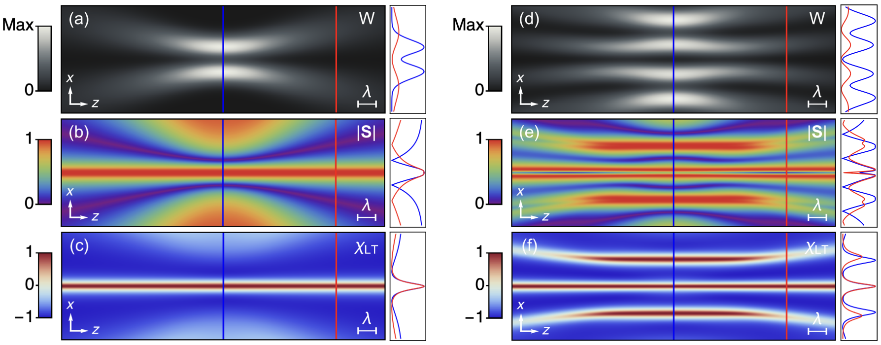
Observe that the longitudinal field component vanishes along the propagation axis, i.e., where leaving nonzero transverse polarization that persists for infinite distance. This phenomena is illustrated in Fig. 1(a), where energy density is nonzero at the phase singularity beyond the Rayleigh length. The significance of nonzero intensity at the center of a vortex beam is widely studied in optics [31], particularly in light-matter interactions [32, 33]. It should be noted that this effect is not found in acoustic Gaussian beams (), which do not possess field nodes.
A straightforward analytical calculation (Eq. (2)) shows that for , the normalized spin AM density at the center of the vortex beam is strictly longitudinal As shown in Fig. 1(b), at the vortex center, corresponding to a line of circular polarization, of which chirality is determined by . It is found that persists for infinite distance, as presented in Fig. 1(b), where plateaus at unity in the vortex center at and . Due to the circular symmetry of the Laguerre-Gaussian beam, only a single line of circular polarization is present along the vortex node. Equivalent results for spin AM density can be derived for acoustic Bessel beams [6], which possess propagation-invariant energy profiles.
Examining the LT-alignment parameter near the phase singularity, , we find that
| (16) |
where As shown in Fig. 1(c), the bounds for are The contour for any acoustic vortex beam of azimuthal order traces out a cylinder of fixed radius that encloses the vortex phase singularity for infinite distance, despite an expanding transverse intensity profile (see Fig. 1(a)).
These non-diffractive features survive in the far-field for velocity fields of local coaxial and non-coaxial superpositions of monochromatic acoustic Laguerre-Gaussian beams, that is, Indeed, when where is the size of the source, the superimposed field components near a persisting longitudinal field zero gives quadratic behavior akin to Eq. (16). Therefore, regardless of the localized source geometry and mixing of radial and azimuthal orders of acoustic vortex beams, there always exists non-diffractive features in distances sufficiently far from the source. We illustrate this phenomenon in Figures 1(d)-(f), which contain intensity and polarization distributions for the non-coaxial superposition of two acoustic vortex beams launched at . Around the longitudinal node propagating at , there exists a pair of C lines that maintain separation of (Fig. 1(e)). Furthermore, as evident in Fig. 1(f), interference of the individual fields result in a far-field non-diverging LT-alignment tube centered around the origin.
IV Acoustic Dipole Array
Consider the pressure field of a dipole with moment , which can be expressed in the form [34]
| (17) |
Note that the zeros of Eq. (17) occur in the plane orthogonal to Thus, for a single dipole, there exists degenerate spin structures that enclose the plane where For example, when a Taylor expansion around of the velocity components which can be derived from Eq. (1), gives the non-divergent contour independent of azimuthal coordinate Note that represents the longitudinal distance above the plane, so separation of the enclosing contour planes in this case is
Here, we examine the superimposed acoustic fields from an array of acoustic dipoles, that is, and where represents the spatial position of the -th dipole. In the far field, the angular array factor can be decomposed from and , which gives the angular positions of persisting field zeros. It follows that the array geometry, described by , determines angular placement of the non-diffracting polarization and spin structures outlined in the formalism in Sec. II.2.
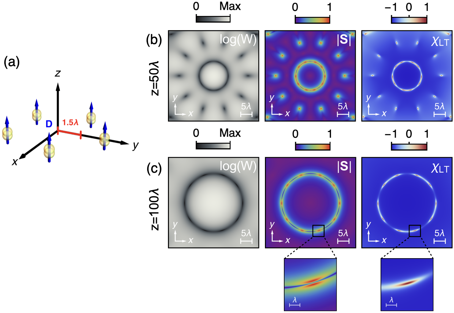
As an example, we consider a pentagonal array of -directed acoustic dipoles distributed over a circle of radius in the plane (see Fig. 2(a) for a schematic diagram). Importantly, we do not neglect the transverse components of , for their relative size is appreciable near the zeros of which enables a nonparaxial description of the velocity fields at certain angular positions in space. As evident in Figs. 2(b, c), the transverse energy density spreads in space with increasing distance from the array. Around each propagating dark spot of intensity, we have pairs of C-lines which maintain invariant separation of with respect to radial distance. Moreover, enclosing each field node is the non-divergent elliptical tube expressed by the relation
V Double-Slit Interference
Our last example is the acoustic version of famous Young’s Double Slit experiment of light interference, which was performed in 1801 and subsequently opened a new avenue for the study of wave optics. We provide a standard theoretical analysis of the experiment, with the inclusion of the 3D velocity field components typically neglected due to the curl-free behavior of sound. It follows that non-divergent pairs of circular polarization singularities sandwich the intensity minima (or dark fringes) of the double-slit interference pattern.
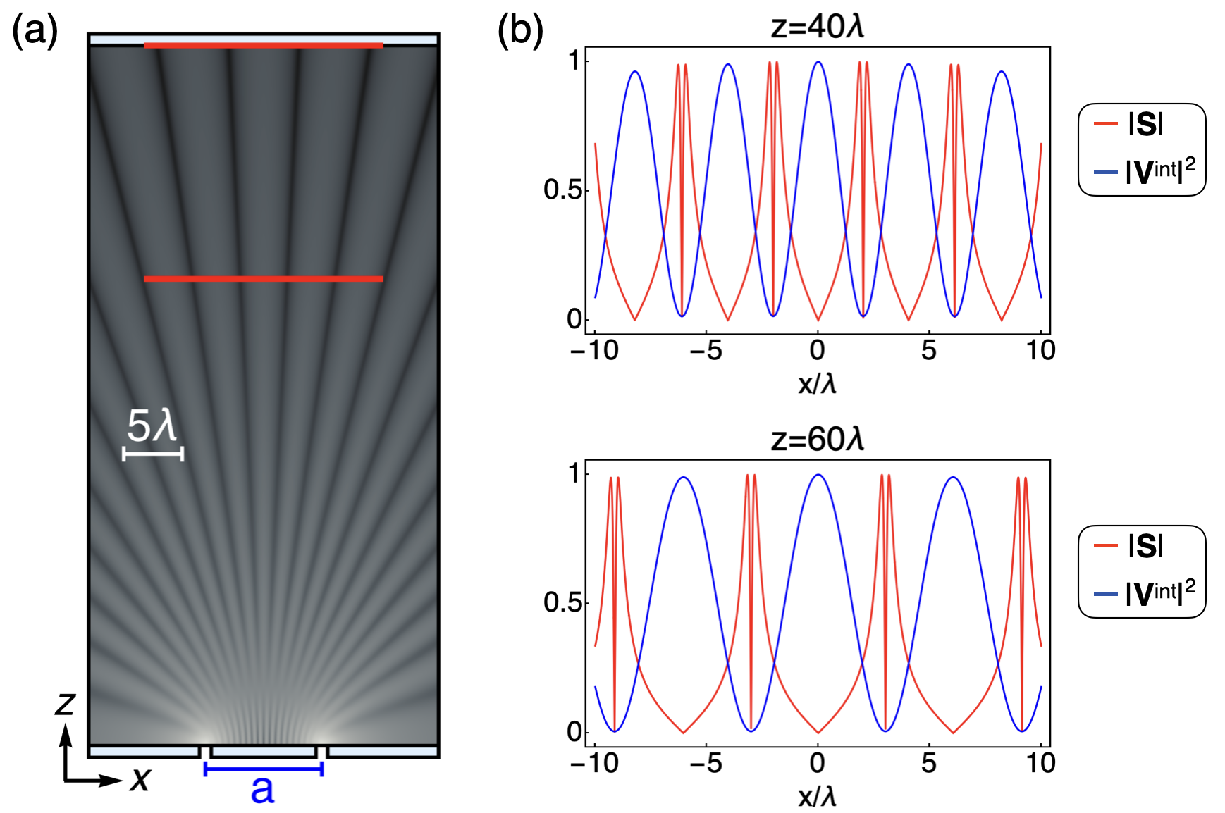
As depicted in Fig. 3(a), the experimental geometry is as follows. Consider a screen that consists of two narrow slits, both oriented in the -direction, with spacing in the -direction. A projection screen (parallel to -plane) is placed a distance from the slits. In the plane, the velocity field at a position on the projection screen can be expressed as the superposition of monochromatic point sources from each slit:
| (18) |
where represents the distance between each slit and the screen measurement position, and in the Cartesian basis, with the condition The path difference , where is an integer, indicates constructive interference and a bright fringe; likewise, destructive interference occurs at , where the dark fringe forms. It follows that the intensity maxima and minima, respectively, occur at the angles and For large distances from the slit screen, the longitudinal velocity field component is dominant in comparison to the transverse , however, evaluating near results in comparable spatial field components. Noting that the angular position of each slit occurs at the ratio of velocity field components is derived to be
| (19) |
In the vicinity of i.e., locations where the Taylor expansion results in as so is a first-order zero at Moreover, the complex ratio , which satisfies the full circular polarization condition , occurs when is offset by independently of the distance between the slits’ plane and the projection screen, corresponding to the path difference Angular offset of the lines with from the dark fringe position is . That is, in the far-field interference pattern emanating from the double slits, we have pairs of circular polarization singularities (C-lines) of opposite spins that maintain a propagation-invariant separation of along -axis across each propagating dark fringe of intensity, as demonstrated in Fig. 3(b).
We notice an important difference from electromagnetism [26]: While for electromagnetic double-slit interference the spinning structures do not form for field polarization aligned with the slits, there is no such a restriction for the longitudinal acoustic pressure waves.
VI Summary and Conclusions
We have presented a theoretical formalism that predicts non-diffractive polarization and spin structures inherent to acoustic fields of arbitrary sources. The far-field patterns of acoustic radiation yield dominant longitudinal velocity fields due to the curl-free nature of sound, however, near longitudinal zeros (i.e., pressure phase singularities) there exists a rich and invariant nonparaxial region that extends to infinity. In general, accompanying each acoustic field node are: a non-divergent elliptical tube whose contour is defined by equality of the longitudinal and transverse velocity fields and pairs of circular polarization singularities with constant sub-wavelength separation. The developed formalism can be extended to elastic waves in solids that would also involve shear waves known to lead to polarization anomalies [35, 36]. The next step in our studies may be an analysis of surface acoustic waves (SAW), for which the polarization singularities predicted here could result in rotation of the velocity field plane near dark fringes of interference.
It is worth comparing our results to those found in electromagnetic fields [25, 26]. Despite the contrasting transverse behavior of electric and magnetic fields (), it was shown that their transverse field zeros generate spinning structures analogous to our present work in acoustics.
Thus, our findings offer fruitful analogies between light and sound, in regards to the interplay of longitudinal and transverse fields near dark spots of intensity. Moreover, we exemplified our general theory with acoustic vortex beams, acoustic dipole arrays, and Young’s double slit experiment. We are hopeful this work provides potential applications in polarization-based communications, acoustic enantioseparation, non-destructive evaluation of materials, and acoustic tweezers.
Acknowledgements.
We wish to acknowledge support from US Army Research Office Award No. W911NF-23-1-0085. AA thanks Michael Berry and Konstantin Bliokh for useful discussions.References
- Berry [2023] M. V. Berry, The singularities of light: intensity, phase, polarisation, Light: Science & Applications 12, 238 (2023).
- Dennis et al. [2009] M. R. Dennis, K. O’Holleran, and M. J. Padgett, Singular Optics: Optical Vortices and Polarization Singularities, edited by E. Wolf, Progress in Optics, Vol. 53 (Elsevier, 2009) pp. 293–363.
- Hefner and Marston [1999] B. T. Hefner and P. L. Marston, An acoustical helicoidal wave transducer with applications for the alignment of ultrasonic and underwater systems, The Journal of the Acoustical Society of America 106, 3313 (1999).
- Courtney et al. [2013] C. R. Courtney, B. W. Drinkwater, C. E. Demore, S. Cochran, A. Grinenko, and P. D. Wilcox, Dexterous manipulation of microparticles using bessel-function acoustic pressure fields, Applied Physics Letters 102, 10.1063/1.4798584 (2013).
- Muelas-Hurtado et al. [2022] R. D. Muelas-Hurtado, K. Volke-Sepúlveda, J. L. Ealo, F. Nori, M. A. Alonso, K. Y. Bliokh, and E. Brasselet, Observation of polarization singularities and topological textures in sound waves, Phys. Rev. Lett. 129, 204301 (2022).
- Bliokh and Nori [2019] K. Y. Bliokh and F. Nori, Spin and orbital angular momenta of acoustic beams, Phys. Rev. B 99, 174310 (2019).
- Bliokh et al. [2021] K. Y. Bliokh, M. A. Alonso, D. Sugic, M. Perrin, F. Nori, and E. Brasselet, Polarization singularities and Möbius strips in sound and water-surface waves, Physics of Fluids 33, 077122 (2021).
- Shi et al. [2019] C. Shi, R. Zhao, Y. Long, S. Yang, Y. Wang, H. Chen, J. Ren, and X. Zhang, Observation of acoustic spin, National Science Review 6, 707 (2019).
- Ge et al. [2021] H. Ge, X.-Y. Xu, L. Liu, R. Xu, Z.-K. Lin, S.-Y. Yu, M. Bao, J.-H. Jiang, M.-H. Lu, and Y.-F. Chen, Observation of acoustic skyrmions, Phys. Rev. Lett. 127, 144502 (2021).
- Ozcelik et al. [2018] A. Ozcelik, J. Rufo, F. Guo, Y. Gu, P. Li, J. Lata, and T. J. Huang, Acoustic tweezers for the life sciences, Nature Methods 15, 1021 (2018).
- Baudoin and Thomas [2020] M. Baudoin and J.-L. Thomas, Acoustic tweezers for particle and fluid micromanipulation, Annual Review of Fluid Mechanics 52, 205 (2020).
- Baresch et al. [2016] D. Baresch, J.-L. Thomas, and R. Marchiano, Observation of a single-beam gradient force acoustical trap for elastic particles: Acoustical tweezers, Phys. Rev. Lett. 116, 024301 (2016).
- Li et al. [2021] J. Li, A. Crivoi, X. Peng, L. Shen, Y. Pu, Z. Fan, and S. Cummer, Three dimensional acoustic tweezers with vortex streaming, Communications Physics 4 (2021).
- Fan et al. [2022] Y. Fan, X. Wang, J. Ren, F. Lin, and J. Wu, Recent advances in acoustofluidic separation technology in biology, Microsystems and Nanoengineering 8 (2022).
- Friend and Yeo [2011] J. Friend and L. Y. Yeo, Microscale acoustofluidics: Microfluidics driven via acoustics and ultrasonics, Rev. Mod. Phys. 83, 647 (2011).
- Li et al. [2020] X. Li, Y. Li, Q. Ma, G. Guo, J. Tu, and D. Zhang, Principle and performance of orbital angular momentum communication of acoustic vortex beams based on single-ring transceiver arrays, Journal of Applied Physics 127, 124902 (2020).
- Heidemann et al. [2012] J. Heidemann, M. Stojanovic, and M. Zorzi, Underwater sensor networks: applications, advances and challenges, Philosophical Transactions of the Royal Society A: Mathematical, Physical and Engineering Sciences 370, 158 (2012).
- Sarvazyan et al. [2013] A. P. Sarvazyan, M. W. Urban, and J. F. Greenleaf, Acoustic waves in medical imaging and diagnostics, Ultrasound in Medicine and Biology 39, 1133 (2013).
- Orazbayev and Fleury [2020] B. Orazbayev and R. Fleury, Far-field subwavelength acoustic imaging by deep learning, Phys. Rev. X 10, 031029 (2020).
- Rufo et al. [2022] J. Rufo, P. Zhang, R. Zhong, L. Lee, and T. Huang, A sound approach to advancing healthcare systems: the future of biomedical acoustics, Nature Communications 13, 3459 (2022).
- Burns et al. [2020] L. Burns, K. Y. Bliokh, F. Nori, and J. Dressel, Acoustic versus electromagnetic field theory: scalar, vector, spinor representations and the emergence of acoustic spin, New Journal of Physics 22, 053050 (2020).
- Eismann et al. [2020] J. S. Eismann, L. H. Nicholls, D. J. Roth, M. A. Alonso, M. A. Alonso, P. Banzer, F. J. Rodríguez-Fortuño, A. V. Zayats, F. Nori, and K. Y. Bliokh, Transverse spinning of unpolarized light, Nature Photonics 15, 156 (2020).
- Bliokh et al. [2014] K. Bliokh, A. Bekshaev, and F. Nori, Extraordinary momentum and spin in evanescent waves, Nature communications 5, 3300 (2014).
- Bekshaev et al. [2015] A. Y. Bekshaev, K. Y. Bliokh, and F. Nori, Transverse spin and momentum in two-wave interference, Phys. Rev. X 5, 011039 (2015).
- Afanasev et al. [2023] A. Afanasev, J. Kingsley-Smith, F. J. Rodríguez-Fortuño, and A. V. Zayats, Nondiffractive three-dimensional polarization features of optical vortex beams, Advanced Photonics Nexus 2, 026001 (2023).
- Vernon et al. [2023] A. J. Vernon, A. Kille, F. J. Rodríguez-Fortuño, and A. Afanasev, Non-diffracting polarisation features around far-field zeros of electromagnetic radiation, Optica 10.1364/OPTICA.502020 (2023), arXiv:2306.03278 [physics.optics] .
- Richard et al. [2020] G. Richard, H. S. Lay, D. Giovannini, S. Cochran, G. C. Spalding, and M. P. Lavery, Twisting waves increase the visibility of nonlinear behaviour, New Journal of Physics 22, 063021 (2020).
- Berry and Dennis [2001] M. Berry and M. Dennis, Polarization singularities in isotropic random vector waves, Proceedings of The Royal Society A: Mathematical, Physical and Engineering Sciences 457, 141 (2001).
- Nye and Hajnal [1987] J. Nye and J. Hajnal, The wave structure of monochromatic electromagnetic radiation, Proceedings of The Royal Society A: Mathematical, Physical and Engineering Sciences 409, 21 (1987).
- Spaegele et al. [2023] C. M. Spaegele, M. Tamagnone, S. W. D. Lim, M. Ossiander, M. L. Meretska, and F. Capasso, Topologically protected optical polarization singularities in four-dimensional space, Science Advances 9, eadh0369 (2023).
- Forbes et al. [2021] K. A. Forbes, D. Green, and G. A. Jones, Relevance of longitudinal fields of paraxial optical vortices, Journal of Optics 23, 075401 (2021).
- Quinteiro et al. [2017] G. F. Quinteiro, F. Schmidt-Kaler, and C. T. Schmiegelow, Twisted-light–ion interaction: The role of longitudinal fields, Phys. Rev. Lett. 119, 253203 (2017).
- Afanasev et al. [2020] A. Afanasev, C. E. Carlson, and H. Wang, Polarization transfer from the twisted light to an atom, Journal of Optics 22, 054001 (2020).
- Wei and Rodríguez-Fortuño [2020] L. Wei and F. J. Rodríguez-Fortuño, Far-field and near-field directionality in acoustic scattering, New Journal of Physics 22, 083016 (2020).
- Helbig and Schoenberg [1987] K. Helbig and M. Schoenberg, Anomalous polarization of elastic waves in transversely isotropic media, The Journal of the Acoustical Society of America 81, 1235 (1987).
- Lee et al. [2017] H. J. Lee, J.-R. Lee, S. H. Moon, T.-J. Je, E.-c. Jeon, K. Kim, and Y. Y. Kim, Off-centered double-slit metamaterial for elastic wave polarization anomaly, Scientific Reports 7, 15378 (2017).