titlesec
Learning Based Dynamic Cluster Reconfiguration for UAV Mobility Management with 3D Beamforming
Abstract
In modern cell-less wireless networks, mobility management is undergoing a significant transformation, transitioning from single-link handover management to a more adaptable multi-connectivity cluster reconfiguration approach, including often conflicting objectives like energy-efficient power allocation and satisfying varying reliability requirements. In this work, we address the challenge of dynamic clustering and power allocation for unmanned aerial vehicle (UAV) communication in wireless interference networks. Our objective encompasses meeting varying reliability demands, minimizing power consumption, and reducing the frequency of cluster reconfiguration. To achieve these objectives, we introduce a novel approach based on reinforcement learning using a masked soft actor-critic algorithm, specifically tailored for dynamic clustering and power allocation.
I Introduction
In modern cell-less wireless network architectures, users are no longer tied to a single access point (AP) but are served simultaneously in non-orthogonal multiple access scenarios by a large number of distributed APs [1]. This has led to a significant transformation of the traditional approach to mobility management from the conventional handover management towards a more dynamic cluster reconfiguration model [2]. Consequently, the conventional notion of coverage has evolved from being centered around individual cells to becoming user-centric.
In this new paradigm, users can now be seamlessly served by a cluster of multiple distributed APs using the same frequency-time resources. However, this cluster configuration must be adjusted dynamically for each user’s mobility and stringent quality of service (QoS) requirements like reliability requirements. Additionally, the cluster configuration can have multiple, often conflicting, objectives at the same time. One crucial aspect is to minimize total transmission power while ensuring the high reliability demanded by modern applications. Moreover, the reliability requirements are dynamic and dependent on the system’s state. For instance, in safety-critical scenarios, such as communication between a central controller and a unmanned aerial vehicle (UAV) near an airport, the need for high reliability is paramount. The variation in reliability demands can also be linked to the dynamic nature of services over time, where each service necessitates a distinct level of reliability [3]. However, this also implies that transmission power can be saved in states where the reliability requirements are not as strict.
Cooperation of APs to form clusters and serve the users can be achieved using diverse techniques, such as coordinated multi-point (CoMP) [4, 5], cloud-radio access network (C-RAN) [6], and cell-free networks [7]. However, achieving the optimal cluster scheme can lead to substantial computational overhead, with complexity growing exponentially with network size [1]. Additionally, devising an efficient power allocation scheme for these dynamic clusters in a wireless interference network poses an even more challenging task [8].
We therefore need a different approach for dynamic cluster formation and optimal power allocation with variable reliability constraints. Machine learning (ML), particularly reinforcement learning (RL), offers an attractive solution for such a dynamic problem. With the ability to learn from the environment, RL can exploit particular properties of UAV communication networks. This allows the agent to strategically leverage movement patterns and line-of-sight (LoS)/non-line-of-sight (NLoS) channel conditions between the UAV and the APs.
In this work, we adopt open-radio access network (O-RAN) as the underlying wireless network architecture. The O-RAN architecture offers diverse network clustering possibilities, driving efficiency advancements. By dividing the physical layer into O-RAN distributed units (O-DUs) and O-RAN radio units (O-RUs) (same as APs), it enables advanced features like ML capabilities [9]. Functional blocks like Near-Real Time RAN Intelligent Controller (Near-RT RIC) support tasks such as QoS and radio connection management. Additionally, O-RAN facilitates network-wide control, promoting cooperation among both O-RUs within the same O-DU and across different O-DUs.
In existing literature, dynamic clustering has been a subject of investigation. In [10], a dynamic clustering using the channel gains between the user and the O-RUs is performed in an O-RAN architecture. While they do not consider learning, their approach is offset by an increased signal overhead and it requires a cluster reconfiguration for all users when adding or removing a user. Beamforming vectors for dynamic clustering of APs for a terrestrial user are designed using RL in [11]. However, they do not consider aerial users with varying reliability constraints. The work in [12] considers varying reliability for aerial users, but restricts scenarios to non-interfering environments with a single user.
In this work, we propose a novel dynamic cluster configuration and power control scheme for a downlink UAV communication system with varying reliability requirements. The main contributions are summarized below.
-
•
We introduce a problem to optimize dynamic clustering and AP power allocation within a wireless interference network. This aims to simultaneously satisfy time-varying reliability demands, minimize power usage, and reduce the frequency of cluster reconfiguration.
-
•
We propose to solve the problem of dynamic clustering and power allocation with the soft actor-critic (SAC) framework. To accommodate the dynamic nature of the state and action space, we employ an action masking technique, enabling our scheme to seamlessly handle the addition or dropping of new users without disrupting already formed clusters.
-
•
We study and compare different performance metrics of the conventional clustering mechanism under different parameters in numerical simulations.
II System Model and Problem Formulation
We consider an O-RAN architecture with a UAV downlink communication scenario, where communication is established from the APs to the UAVs, as depicted in Figure 1. In a given area, we have O-RUs (APs) deployed at fixed locations within a certain coverage area. All the O-RUs are connected to the O-Cloud with virtualization and processing resource-sharing capabilities [13]. A total of UAVs, also referred to as aerial users (AUs), are moving inside of the coverage area at the same time. All the AUs are equipped with a single antenna while each O-RU is equipped with antennas. When AU enters the coverage area of the O-Cloud, a non-empty set of O-RUs, , forms a cluster to serve AU . Therefore, the total received power at AUs at time is given as
| (1) |
where denotes the transmit power of O-RU to user , and is the power attenuation between O-RU and user , i.e., the combined path loss and fading effects. These effects are modeled according to [14]. With the known location of the user, we incorporate the 3D beamforming and beamtracking by leveraging the antenna radiation pattern and the steering vectors [15, 16]. For this, represents the antenna array gain from O-RU to user , which is located at an elevation angle of and azimuth angle of with respect to the O-RU. The antenna array gain is given by
where represents the constant array gain, while and represent the steering vectors in the elevation and azimuth directions, respectively. The vectors and are given according to [16] as
| (2) | ||||
| (3) |
where, and denote column vectors of ones of sizes and respectively. The number of antennas in and directions of the antenna array are and , respectively. The and represent the antenna spacing in the and directions, respectively, and represents the wave number.
For the ease of reading, we omit the time index , unless it is necessary to explicitly specify it.
With the above, the receive signal-to-interference-plus-noise ratio (SINR) at the target AU served by cluster is:
| (4) |
where is the noise density, and the interference power is the sum of all received power from all O-RUs serving on the same resource to other AUs.

While we assume that the positions of the AUs and the fading statistics are known, the exact channel state is assumed unknown. Hence, the user will be in an outage with a non-zero probability when the SINR at the AU is below a predefined threshold , i.e., the outage probability for user at time is given as
| (5) |
Depending on the specific use case, there exists an outage probability requirement, denoted as , that is deemed acceptable. However, it is essential to acknowledge that this tolerance level is influenced by various factors and may change over time, e.g., when the user moves into a different area. In this study, we focus on a particular scenario where a specific region is considered critical, demanding a higher level of reliability, denoted as . Outside this critical area, it suffices for the outage probability to be lower than , with .
II-A SINR Outage
In the following, we derive an expression for calculating the outage probability from (5) for a single time slot , i.e., for a fixed power allocation and fixed positions of all users. In this case, we can rewrite the outage probability as the probability of a new random variable that comprises of a sum of exponentially distributed random variables with different expected values,
| (6) |
where is the product of the SINR threshold and the interference power at user . Based on the Rayleigh fading model, the random variable is given as the sum of exponentially distributed variables with different expected values . The expected values are given by the product of transmit power, antenna gain, and path loss. The survival function of is given by [17]
| (7) | ||||
| (8) |
For this expression to hold, we need to assume that all are distinct. However, since they are the product of transmit power, antenna gain, and path loss, this assumption will hold almost surely in practice.
II-B Mobility Model
In this work, we employ a realistic and tractable mobility model to capture the mobility of UAVs. In particular, we use the model provided in [18] using coupled stochastic differential equations. By utilizing estimated positions instead of actual ones, the model incorporates more realistic device trajectories and considers imperfect navigation. The advantage of this approach lies in its ability to generate smoother and realistic trajectories. Additionally, it provides better control over velocity through correlation parameters, which influence stability and mobility based on distance-velocity relationships. Additional variance parameters scale Brownian perturbations, offering flexibility in introducing stochastic variations. For detailed explanations of the model, please refer to the original work [18]. Overall, this carefully chosen model accurately represents UAV mobility, accounting for practical considerations and enhancing the realism of trajectory generation.
II-C User Handling
For a more realistic and dynamic scenario, our system needs to efficiently manage users entering and leaving the coverage area without disrupting the already established clusters.
II-C1 Users Entering the Coverage Area
When a completely new mobile user enters the coverage area of the system, they were not previously associated with the system. As a result, they become part of the active user group and are served by a new O-RU cluster. This ensures that new users seamlessly receive services within the existing system framework.
II-C2 User Leaves the Coverage Area
On the other hand, active users can become inactive, e.g., by moving out of the service area or switching off their devices. As a result, they transition from an active to a non-active state and are no longer served by the O-RU cluster they were previously associated with. This allows for efficient management of resources and ensures optimal service distribution to active users.
II-D Problem Formulation
The seamless integration of dynamic clustering and power allocation for O-RUs is of utmost importance to ensure both reliable and energy-efficient communication. To accomplish this objective, we present an optimization problem aimed at finding the optimal serving cluster for each user and the corresponding power allocation vector. The primary objective is twofold: The reliability of every user should be maximized, i.e., minimizing outages, while simultaneously minimizing the overall transmit power and the need for cluster reconfiguration arising from user movements. These two objectives are in conflict with each other since reducing the transmit power will in general lead to an increase of the outage probability. Additionally, due to the movement of the users, optimal power allocation and the serving cluster vary over time. Based on this, we use a scalarization to formulate the general multi-objective optimization problem of O-RUs clustering and power allocation as
| (9a) | ||||
| s.t. | (9b) | |||
| (9c) | ||||
where , , are objective functions that measure the system’s cost of cluster reconfiguration, reliability, and total transmit power, respectively. The constraint states the transmitted power is limited by , while makes sure all the users are served. The exact choice of these functions will be described in the following Section III.
The formulated optimization problem (9) is non-convex. Although employing sophisticated optimization techniques can potentially yield the globally optimal solution, the high complexity of such approaches poses significant practical challenges [8]. This is particularly evident in scenarios characterized by dynamic channel variations, necessitating frequent updates to power control policies to ensure viable solutions.
III Proposed Solution With Reinforcement Learning
In this section, we provide a RL-based solution to solve problem (9) by assuming that an agent is located at each Near-RT RIC (also referred to as O-Cloud), which is connected with the O-RUs in the coverage area. The Near-RT RIC with virtualization and processing resource sharing capabilities collects the required information from all the connected O-RUs. Using the trained model, it assigns a serving cluster with power allocation to all the AUs.
In the context of interference networks, the action that the RL agent takes, corresponds to a matrix of all transmit powers for all O-RU-user pairs. The observation space consists of the current locations of all UAVs, the LoS/NLoS conditions between each user and base station pair, and the status (active/inactive) of all the UAVs. Based on the action (power allocation) and observations (locations, LoS condition), the outage probabilities for all users can be calculated.
We model our problem as a Markov decision process (MDP) and transform the optimization problem as outlined in (9) into the reward function within the RL framework. We first describe the functions used in (9a) to measure the system’s cost of cluster reconfiguration, reliability, and transmit power. The function that describes the system’s cost of cluster reconfiguration is defined as:
| (10) |
which provides the proportion of clusters that have changed. The function describing the reliability is defined as:
| (11) |
which gives the fraction of users who are in the outage.
Finally, the function that describes the system’s transmit power is defined as:
| (12) |
which captures the total transmit power as a fraction of the maximum total transmit power.
To calculate the overall reward and make it a positive quantity, we formulate the function as
| (13) |
where the non-negative weights , , are used to balance between the individual objectives. The reward in (13) increases when the stable clusters or non-outage users increase, while minimizing total transmit power.
As the learning algorithm, we employ the state-of-the-art RL algorithm SAC, which optimizes the behavior of an agent given a state with the trial-and-error method. SAC optimizes an agent’s behavior through a trial-and-error approach, employing a deep neural network (DNN) policy that generates stochastic actions based on the state. It incorporates entropy regularization to promote exploration, balance exploration-exploitation trade-offs, and prevent premature convergence to suboptimal policies.
To ensure efficient handling of dynamically changing observation and action space resulting from the movement of mobile users into and out of the service area, we employ a technique called action masking [19]. Action masking involves setting the probability of allocating resources, such as power, to inactive users to zero. This effectively prevents the agent from taking actions that allocate resources to inactive users. Action masking is a valuable tool for streamlining the learning process, allowing the agent to focus on relevant actions while disregarding those that pertain to inactive users. In our context, this enables us to effectively manage the dynamic nature of users entering and leaving the coverage area. This targeted approach facilitates rapid adaptation of the agent’s strategies and policies to the changing environment, leading to more effective resource management and improved overall performance.
We propose enhancing the SAC algorithm with action masking. Throughout the following, we refer to this as masked soft actor-critic (MSAC). An overview can be found in Algorithm 1. This masking approach allows us to focus on relevant actions, excluding those associated with inactive users. This optimization streamlines learning and empowers the agent to make more efficient decisions. By combining the adaptability of SAC with strategic action masking, we effectively manage the environment’s dynamic nature, accommodating varying user presence, and optimizing resource allocation for enhanced performance. However, we still need to fix a maximum number of users that can be supported in the coverage area.
IV Numerical Evaluation
| Parameters | Train | Test |
|---|---|---|
| Learning rate | ||
| Batch size | ||
| Soft update coefficient | ||
| Entropy coefficient | auto | auto |
| Iterations |
In this section, we showcase the effectiveness of our proposed MSAC implementation in solving (9). Additionally, we benchmark our MSAC algorithm against two baseline methods. The first baseline is the Opportunistic cluster formation algorithm from [10], where O-DUs opportunistically decides to include an O-RUs in a cluster for user service based on channel gains. The second baseline follows the Closest strategy, where only the nearest O-RU serves the user with maximum power. For a fair comparison, we keep all parameters of the communication system the same for all algorithms. There are users in a square area of . They are served by O-RUs, which are placed randomly within this area with a height of , cf. Figure 1. Each O-RU is equipped with antennas. The model of the path-loss follows [14], where we set the carrier frequency to to accommodate a broader range for command and control traffic for the UAVs. Additionally, we set the SINR threshold, denoted as , to . The noise power at the receiver is given as , where is the communication bandwidth, and is the noise spectral density. The UAVs move randomly following the mobility model described in Section II-B across the area. The critical area with the higher reliability demand is located within in both - and -direction. In this area, the outage requirement is set to , while it is everywhere else.
Leveraging the aforementioned parameters to generate channel information, we formulate our problem as a MDP within OpenAI’s Gym environment framework. Following each iteration, the agent’s policy generates values for the outage, transmit power, and cluster reconfiguration indicator. Using these values, the step reward (13) is calculated and fed back to the agent. The initial agent hyperparameters are summarized in Table I, having been empirically determined through multiple iterations. The source code of our implementation for reproducing all of the shown results is made publicly available at [20].
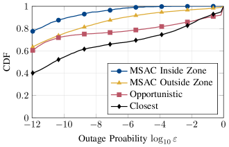
For the described scenario above, the outage probability results can be found in Figure 2. The CDF shows the distribution of the outage probability for the users during their mobility in the service area. It can be observed that the proposed MSAC algorithm outperforms the Opportunistic and Closest strategies. The proposed MSAC performs better and learns about the stricter reliability constraint inside the high-reliability zone. The agent can adopt the transmit power from the set of O-RUs given the position of the users and LoS conditions. The proposed MSAC algorithm exploits the spatial relationships among the neighboring O-RUs and LoS conditions to mitigate interference and thus meet the requirements. It can be observed that inside the high reliability zone, we consistently meet the outage requirement of at all times. Outside this zone, we achieve the outage requirement approximately of the time. This behavior arises because the outage constraint is not strictly enforced in the reward function, but the agent can prioritize saving transmit power over meeting this requirement. One way to address this challenge in future work is to change the reliability reward to employ a barrier-type function, e.g., a logarithmic function. Although the Opportunistic outperforms the Closest strategy, the latter approach generates less interference by having only one O-RU serve each user, but this impacts received power and subsequently increases the outage. However, both schemes are not able to differentiate between the high-reliability zone and meet the stricter requirements.
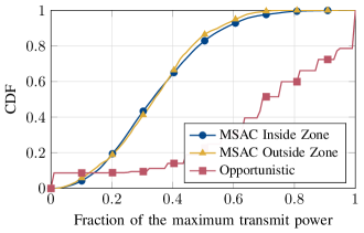
The results for the used power to compare the proposed MSAC with the Opportunistic are provided in Figure 3. Since the transmit power is constant in the Closest scheme, we omit it from the graph. To holistically assess the performance of MSAC, it is essential to consider the combined insights from both Figure 2 and Figure 3. The observations drawn from Figure 3 indicate that the proposed MSAC utilizes less than of the maximum available transmit power in of the time. This underscores that the proposed scheme not only excels in mitigating outages and effectively distinguishes between varying reliability zones, but it also achieves these outcomes with a notable reduction in total transmitted power.
The third objective in our problem is the formation of clusters. The distribution of the average cluster size for serving mobile UAVs is depicted in Figure 4. Notably, the distribution for MSAC is centered, indicating its tendency to utilize half or fewer O-RUs to form clusters. Through training, the MSAC agent adeptly balances outage requirements and the number of O-RUs per cluster. In contrast, the Opportunistic scheme, driven by favorable channel conditions, often involves over of O-RUs in clusters, resulting in excessive power usage. Additionally, it is intriguing to note that MSAC maintains nearly zero probability for cluster sizes greater than or equal to , whereas the Opportunistic scheme exhibits the highest probability for a cluster size of , i.e., involving all O-RUs in a cluster.

V Conclusion
Mobility management in the context of multi-connectivity involves real-time complex decision-making. Dynamic cluster reconfiguration, compounded by time-varying reliability requirements and energy-efficient power allocation, presents a formidable challenge.
In this study, we have employed a model-free RL algorithm to optimize dynamic cluster reconfiguration and associated power control under varying reliability demands. Our primary objective has been to minimize the total transmit power of all APs within each cluster with minimum cluster reconfigurations while ensuring that outage probabilities remain below specified thresholds. These thresholds can change dynamically, such as when a UAV enters a critical zone with heightened reliability requirements. Additionally, our approach accommodates the dynamic nature of observation and action spaces resulting from the arrival and departure of the mobile AUs to and from the service area. We have achieved this by enhancing the SAC algorithm through action masking.
References
- [1] Selcuk Bassoy, Hasan Farooq, Muhammad A Imran and Ali Imran “Coordinated multi-point clustering schemes: A survey” In IEEE Commun. Surveys Tuts. 19.2 IEEE, 2017, pp. 743–764
- [2] Fenghe Hu, Yansha Deng and A Hamid Aghvami “Scalable multi-agent reinforcement learning for dynamic coordinated multipoint clustering” In IEEE Trans. Commun. 71.1 IEEE, 2022, pp. 101–114
- [3] Xiaojie Wang et al. “Dynamic UAV Deployment for Differentiated Services: A Multi-Agent Imitation Learning Based Approach” In IEEE Trans. Mobile Comput. 22.4 Institute of ElectricalElectronics Engineers (IEEE), 2023, pp. 2131–2146 DOI: 10.1109/tmc.2021.3116236
- [4] Yanpeng Dai et al. “Joint optimization of BS clustering and power control for NOMA-enabled CoMP transmission in dense cellular networks” In IEEE Trans. Veh. Technol. 70.2 IEEE, 2021, pp. 1924–1937
- [5] Weidong Mei, Qingqing Wu and Rui Zhang “Cellular-Connected UAV: Uplink Association, Power Control and Interference Coordination” In IEEE Trans. Wireless Commun. 18.11 Institute of ElectricalElectronics Engineers (IEEE), 2019, pp. 5380–5393 DOI: 10.1109/twc.2019.2936021
- [6] Aleksandra Checko et al. “Cloud RAN for mobile networks — A technology overview” In IEEE Commun. Surveys Tuts. 17.1 IEEE, 2014, pp. 405–426
- [7] Emil Björnson and Luca Sanguinetti “Making cell-free massive MIMO competitive with MMSE processing and centralized implementation” In IEEE Trans. Wireless Commun. 19.1 IEEE, 2019, pp. 77–90
- [8] Bho Matthiesen et al. “A Globally Optimal Energy-Efficient Power Control Framework and its Efficient Implementation in Wireless Interference Networks” In IEEE Trans. Signal Process. 68 IEEE, 2020, pp. 3887–3902 DOI: 10.1109/TSP.2020.3000328
- [9] Andres Garcia-Saavedra and Xavier Costa-Perez “O-RAN: Disrupting the virtualized RAN ecosystem” In IEEE Communications Standards Magazine 5.4 IEEE, 2021, pp. 96–103
- [10] Robbert Beerten, Vida Ranjbar, Andrea P Guevara and Sofie Pollin “Cell-Free Massive MIMO in the O-RAN Architecture: Cluster and Handover Strategies”, 2023 arXiv:2301.07618v1 [eess.SP]
- [11] Yasser Al-Eryani, Mohamed Akrout and Ekram Hossain “Multiple access in cell-free networks: Outage performance, dynamic clustering, and deep reinforcement learning-based design” In IEEE J. Sel. Areas Commun. 39.4 IEEE, 2020, pp. 1028–1042
- [12] Irshad A. Meer et al. “Reinforcement Learning Based Dynamic Power Control for UAV Mobility Management” In 2023 57th Asilomar Conference on Signals, Systems, and Computers IEEE, 2023 arXiv:2312.04742 [cs.IT]
- [13] Özlem Tuğfe Demir, Meysam Masoudi, Emil Björnson and Cicek Cavdar “Cell-Free Massive MIMO in O-RAN: Energy-Aware Joint Orchestration of Cloud, Fronthaul, and Radio Resources”, 2023 arXiv:2301.06166 [eess.SP]
- [14] “Enhanced LTE Support for Aerial Vehicles”, 2017 3GPP
- [15] Irshad A. Meer, Mustafa Ozger and Cicek Cavdar “Cellular localizability of unmanned aerial vehicles” In Vehicular Communications 44 Elsevier BV, 2023 DOI: 10.1016/j.vehcom.2023.100677
- [16] Achiel Colpaert, Evgenii Vinogradov and Sofie Pollin “3D beamforming and handover analysis for UAV networks” In 2020 IEEE Globecom Workshops (GC Wkshps), 2020
- [17] S.V. Amari and R.B. Misra “Closed-form expressions for distribution of sum of exponential random variables” In IEEE Trans. Rel. 46.4, 1997, pp. 519–522 DOI: 10.1109/24.693785
- [18] Peter J. Smith et al. “Flexible Mobility Models Using Stochastic Differential Equations” In IEEE Trans. Veh. Technol. 71.4 IEEE, 2022, pp. 4312–4321 DOI: 10.1109/TVT.2022.3146407
- [19] Shengyi Huang and Santiago Ontañón “A Closer Look at Invalid Action Masking in Policy Gradient Algorithms” In International FLAIRS Conference 35 University of Florida George A Smathers Libraries, 2022 DOI: 10.32473/flairs.v35i.130584
- [20] Irshad A. Meer and Karl-Ludwig Besser “Learning Based Dynamic Cluster Reconfiguration for UAV Mobility Management with 3D Beamforming”, 2024 URL: https://github.com/Irshadmeer/ICMLCN-2024-Dynamic-Clustering