Paderborn University, Germany and https://www.uni-paderborn.de/person/32229 krijan@mail.upb.dehttps://orcid.org/0000-0001-9464-295X Paderborn University, Germany and https://www.uni-paderborn.de/person/55557 liedtke@mail.upb.dehttps://orcid.org/0000-0002-4066-0033 Paderborn University, Germany and https://cs.uni-paderborn.de/ti/personal/prof-dr-rer-nat-christian-scheideler scheideler@upb.dehttps://orcid.org/0000-0002-5278-528X \CopyrightDavid Liedtke and Kristian Hinnenthal and Christian Scheideler \ccsdesc[500]Theory of computation Design and analysis of algorithms \fundingThis work was supported by the DFG Project SCHE 1592/10-1.\EventEditorsJohn Q. Open and Joan R. Access \EventNoEds2 \EventLongTitle42nd Conference on Very Important Topics (CVIT 2016) \EventShortTitleCVIT 2016 \EventAcronymCVIT \EventYear2016 \EventDateDecember 24–27, 2016 \EventLocationLittle Whinging, United Kingdom \EventLogo \SeriesVolume42 \ArticleNo23
Efficient Shape Formation by 3D Hybrid Programmable Matter: An Algorithm for Low Diameter Intermediate Structures
Abstract
This paper considers the shape formation problem within the 3D hybrid model, where a single agent with a strictly limited viewing range and the computational capacity of a deterministic finite automaton manipulates passive tiles through pick-up, movement, and placement actions. The goal is to reconfigure a set of tiles into a specific shape termed an icicle. The icicle, identified as a dense, hole-free structure, is strategically chosen to function as an intermediate shape for more intricate shape formation tasks. It is designed for easy exploration by a finite state agent, enabling the identification of tiles that can be lifted without breaking connectivity. Compared to the line shape, the icicle presents distinct advantages, including a reduced diameter and the presence of multiple removable tiles. We propose an algorithm that transforms an arbitrary initially connected tile structure into an icicle in steps, matching the runtime of the line formation algorithm from prior work. Our theoretical contribution is accompanied by an extensive experimental analysis, indicating that our algorithm decreases the diameter of tile structures on average.
keywords:
Programmable Matter, Shape Formation, 3D Model, Finite Automaton1 Introduction
Advancements in molecular engineering have led to the development of a series of computing DNA robots designed for nano-scale operations. These robots are intended to perform simple tasks such as transporting cargo, facilitating communication, navigating surfaces of membranes, and pathfinding [28, 1, 21, 4]. Envisioning the future of nanotechnology, we anticipate a scenario where a collective of computing particles collaboratively acts as programmable matter – a homogeneous material capable of altering its shape and physical properties programmably. There are numerous potential applications: For environmental remediation, particles may construct nanoscale filtration systems to remove pollutants from air or water. They may also be deployed within the human body to construct intricate structures for targeted drug delivery, perform nanoscale surgeries, or repair damaged tissues at a cellular level. Additionally, they could assemble nanoscale circuits and components, enabling the development of more efficient and compact electronic devices. Each of those scenarios is an application of the shape formation problem, which is the subject of this paper.
Over the past few decades, various models of programmable matter have emerged, primarily distinguished by the activity of entities within them. Passive systems consist of entities (called tiles) that undergo movement and bonding exclusively in response to external stimuli, such as current or light, or based on their inherent structural properties, such as specific glues on the surfaces of tiles. Examples of these passive systems include the DNA tile assembly models aTAM, kTAM, and 2HAM, which are extensively discussed in the survey [24], as well as population protocols [2], and slime molds [5]. In contrast, active systems consist of entities (called particles, agents or robots) that independently perform computation and movement to accomplish tasks. Notable examples encompass the Amoebot model [7], modular self-reconfigurable robots [26, 29], the nubot model [33], metamorphic robots [6, 30], and swarm robotics [32].
While fabricating computing DNA robots remains challenging, producing simple passive tiles from folded DNA strands is efficient and scalable [14]. The hybrid model of programmable matter [12, 13, 15, 22, 18] offers a compromise between feasibility and utility. This model involves a small number of active agents with the computational capabilities of deterministic finite automata together with a large set of passive building blocks, called tiles. Agents can manipulate the structure of tiles by picking up a tile, moving it, and placing it at some spot. A key advantage of the hybrid approach lies in the reusability of agents upon completing a task, where in purely active systems, particles become part of the formed structure.
In this paper, we address the shape formation problem within the 3D hybrid model, with the ultimate goal of transforming an arbitrary initial arrangement of tiles into a predefined shape. We consider tiles in the shape of rhombic dodecahedra, i.e., polyhedra featuring 12 congruent rhombic faces, positioned at nodes within the adjacency graph of face-centered cubic (FCC) stacked spheres (see Figure 1(a)). Unlike rectangular tiles, the rhombic dodecahedron presents a distinct advantage: it allows an agent to orbit around a tile without risking connectivity. This property is particularly valuable in liquid or low gravity environments, where it prevents unintended separation between the agents and the tiles.
Achieving universal 3D shape formation faces a key challenge: identifying tiles that can be lifted without disconnecting the tile structure (referred to as removable tiles). Even if such tiles exist, locating them requires exploring the tile structure, demanding memory bits for graphs with a diameter and degree [11]. When limited to constant memory, navigating plane labyrinths requires two placeable markers (pebbles) [16, 3]. In the 2D context, finding removable tiles is impossible without prior modification of the tile structure, as discussed in [13]. Moreover, the complexity increases significantly in 3D, where instances exist in which any tile movement can result in disconnection. To address these challenges, we make the assumption that the agent carries a tile initially, using it to uncover removable tiles through successive tile movements. It is still entirely unclear whether otherwise a removable tile can be found in all 3D instances. For that reason, our primary goal is to construct an intermediate structure that is easily navigable by constant-memory agents and allows the identification of removable tiles without relying on an initially carried tile.
1.1 Our Contribution
The intermediate structure we propose is termed an icicle, characterized by a platform representing a parallelogram and downward-extending lines of tiles from the platform (see Figure 1(a)). We present a single-agent algorithm that transforms any initially connected tile structure into an icicle in steps, matching the efficiency of the line formation algorithm from prior work [15]. While both the icicle and the line enable agents without an initial tile to find removable tiles, the icicle presents distinct advantages. In the best-case scenario, the diameter of an icicle can be as low as , whereas a line consistently maintains a diameter of . Furthermore, an icicle encompasses multiple removable tiles, which removes the necessity to traverse the intermediate shape completely to locate a removable tile. Our paper includes comprehensive simulation results, indicating that, on average, our algorithm reduces the diameter of the tile structure. In addition, the runtime observed in the simulations consistently falls below the bound established in our runtime analysis. Across all simulations, the runtime remains well within the vicinity of . It is noteworthy that we identified an edge case where the diameter could increase by a factor of , although we believe this to be the worst-case.
1.2 Related Work
The 3D variant of the hybrid model was introduced in [15], where the authors presented an algorithm capable of transforming any connected input configuration into a line in steps. In [18], the authors address the coating problem, providing a solution that solves the problem in worst-case optimal steps. They assume a single active agent that has access to a constant number of distinguishable tile types.
Significant progress has been made in recent years regarding the 2D version of the hybrid model. For instance, in [13], the authors address the 2D shape formation problem, presenting algorithms for a single active agent that efficiently constructs line, block, and tree structures - each being hole-free structures with specific advantages and disadvantages — in worst-case optimal steps. Another publication, [12], explores the recognition of parallelograms with a specific height-to-length ratio. The most recent publication [22] solves the problem of maintaining a line of tiles in presence of multiple agents and dynamic failures of the tiles.
Closely tied to the hybrid model is the well-established Amoebot model, where computing particles traverse an infinite triangular lattice through expansions and contractions. In [8], the authors showcase the construction of simple shapes like hexagons or triangles within the Amoebot model. Expanding on this work, [9] introduces a universal shape formation algorithm capable of constructing an arbitrary input shape using a constant number of equilateral triangles, with the scale depending on the number of amoebots. Notably, this work assumes common chirality, a sequential activation schedule, and randomization. Subsequent improvements are presented in [10], where a deterministic algorithm is introduced, enabling amoebots to form any Turing-computable shape without the need for common chirality or randomization. In [19], the authors consider shape formation in the presence of a finite number of faults, where a fault resets an amoebot’s memory. They solve the hexagon formation problem, assuming the existence of a fault-free leader. A recent extension of the Amoebot model, discussed in [23], considers joint movements of Amoebots. The authors simulate various shape formation algorithms as a proof of concept.
In both [13] and this paper, shape formation algorithms are introduced that construct an intermediate shape, intended to serve as the foundation for more advanced shape formation algorithms. A similar strategy is explored in [17], where 2D lattice-based modular robots initially transform into a canonical shape before achieving the final desired shape. An approach that does not rely on canonical intermediate structures is considered in [25]. The authors present primitives for the Amoebot model that establish shortest path trees within the amoebot structure and subsequently directly route amoebots to their target position.
The concept of shape formation is extensively studied in the field of modular robotics and metamorphic robots, often referred to as self-reconfiguration. A comprehensive survey on this topic can be found in [27]. In the field of swarm robotics, shape formation is often closely related to the problem of computing collision-free paths [31, 20].
1.3 Model Definition
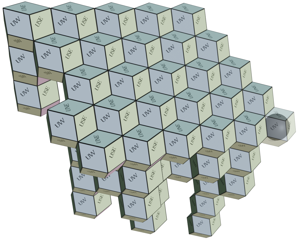

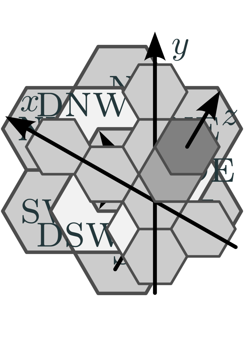

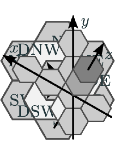
We consider a single active agent with limited sensing and computational power that operates on a finite set of passive tiles positioned at nodes of some specific underlying graph , which we define in the following. Consider the close packing of equally sized spheres at each point of the infinite face-centered cubic lattice. Let be the adjacency graph of spheres in that packing, and consider an embedding of in in which all edges have equal length, e.g., the trivial embedding where the edge length equals the radius of the spheres. Cells in the dual graph of w.r.t. that embedding have the shape of rhombic dodecahedra, i.e., polyhedra with 12 congruent rhombic faces (see Figure 1(a)). This is also the shape of every cell in the Voronoi tessellation of , i.e., that shape completely tessellates 3D space. Consider a finite set of tiles that have the shape of rhombic dodecahedra. Tiles are passive, in the sense that they cannot perform any computation or movement on their own. A node is tiled, if there is a passive tile positioned at ; otherwise node is empty. Each node can hold at most one tile and each tile is placed at at most one node at a time. Each node in has precisely twelve neighbors whose relative positions are described by the twelve compass directions and de (see Figures 1(b), 1(c) and 1(d)). Take note that contains infinitely many copies of the infinite triangular lattice, which serves as the underlying graph in the 2D variant. This allows us to visually depict 3D examples as a stack of 2D hexagonal tiles, as shown in Figure 1.
A configuration is the set that contains all tiled nodes together with the agent’s position . We call connected, if is connected or if is connected and the agent carries a tile, where denotes the subgraph of induced by some nodeset . That is, we allow the subgraph induced by all tiled nodes to disconnect, as long as a tile carried by the agent maintains connectivity. This constraint prevents the agent and tiles to drift apart, e.g., in liquid or low gravity environments.
The agent is the only active entity in this model. It has strictly limited sensing and computing power and can act on passive tiles by picking up a tile, moving and placing it at some spot. Particularly, we assume an agent with the computational capabilities of a deterministic finite automaton that performs discrete steps of Look-Compute-Move cycles. In the look-phase, the agent observes whether its current position and the twelve neighbors of are tiled or empty. The agent is equipped with a compass that allows it to distinguish the relative positioning of its neighbors using the twelve above mentioned compass directions. Its initial rotation and chirality can be arbitrary, but we assume that it remains consistent throughout the execution. For ease of presentation, our algorithms and their analysis are described according to the robot’s local view, i.e., we do not distinguish between local and global compass directions. Based on the information gathered in the look phase, the agent determines its next state transition according to the finite automaton in the compute-phase. In the move phase, the agent performs an action that corresponds to the prior state transition. It either (i) moves to an empty or tiled node adjacent to , (ii) places a tile at , if and carries a tile, (iii) picks up a tile from , if and carries no tile, or (iv) terminates. The agent can carry at most one tile at a time and during actions (ii) and (iii) the agent loses and gains a tile, respectively. that the agent is initially positioned at a tiled node, as otherwise, there might be no valid action available. Additionally, we assume that the agent initially carries a tile, a justification for which is provided in Section 1.1. While the agent is technically a finite automaton, we describe algorithms from a higher level of abstraction textually and through pseudocode. It is easy to see that a constant number of variables of constant-size domain each can be incorporated into the agent’s constantly many states.
1.4 Problem Statement
Consider an arbitrary initially connected configuration with . Superscripts in our notation generally refer to step numbers and may be omitted if they are clear from the context. An algorithm solves the icicle formation problem, if its execution results in a sequence of connected configurations such that nodes in are in the shape of an icicle (which we define below), results from for by applying some action (i)–(iii) to , and the agent terminates (iv) in step .
For some node , we denote the node that is neighboring in some compass direction x and the opposite compass direction of x, e.g., . We call a maximal consecutive array of tiles in direction n and s a column, in direction nw and se a row, and in direction une and dsw a tower. A parallelogram is a maximal consecutive array of equally sized columns (ordered from west to east) whose southernmost tiles at nodes are contained in the same row, i.e., for all . In a partially filled parallelogram, column can have smaller size than columns .
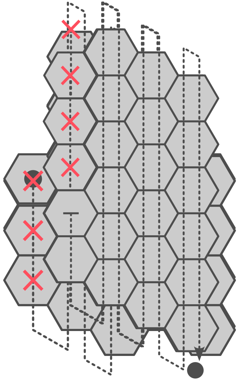
An icicle is defined as a connected set of towers whose uppermost tiles are contained within the same (partially filled) parallelogram, as illustrated in Figure 1(a). In other words, tiles ‘grow’ from a single uppermost parallelogram in the dsw direction, hence the chosen name ‘icicle’. Notably, in an icicle, any tile with a neighboring tile at une but not at dsw (some locally dsw-most tile below the parallelogram) can be picked up without violating connectivity (it is removable). If there is no such tile, i.e., all towers have size one, the northernmost tile of the westernmost column is removable.
1.5 Structure of the Paper
In Section 2, we introduce essential terminology crucial for understanding the algorithm and its subsequent analysis. The non-halting icicle-formation algorithm is presented in Section 3. In Section 4, we provide formal proofs establishing that the algorithm converges any initially connected configuration into an icicle. The termination criteria and a detailed analysis of its runtime are discussed in Section 5. Finally, Section 6 explores the simulation results, including what we believe to be the worst-case configuration in terms of diameter increase.
2 Preliminaries
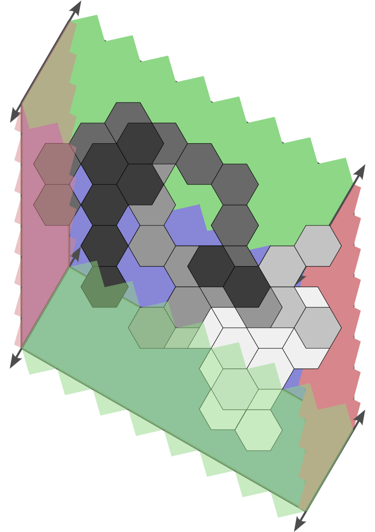
We assign and coordinates to each node , denoted by , where the -coordinates grow from se to nw, -coordinates from s to n, and -coordinates from dsw to une (see Figure 2(a)). The coordinates transition between neighbors as follows:
Observation 1.
Let be some reference node with . The following holds:
Given some nodeset , let be the minimum and maximum -coordinate of any node in , and define and accordingly. We normalize coordinates according to the minimum coordinates in the initial set of tiled nodes , i.e., we set we set . The bounding cylinder is the set of all nodes (both empty and tiled) whose coordinates are bounded by the minimum and maximum - and -coordinates in , i.e., (see Figure 2(b)). Similarly, in the bounding box we further bound by the -coordinate, i.e., . We refer to the extent of a bounding box along the -, - and -axes as its width, height, and depth. Note that by the choice of our coordinate axes, the bounding box is always a filled (potentially degenerated) parallelepiped (a 3D rhomboid; see Figure 2(c)). A node is inside the bounding cylinder (box) of , if (); otherwise, is outside of the bounding cylinder (box) of .

A layer is the set of all nodes with -coordinate that are contained in the bounding cylinder of all tiled nodes, i.e., . We refer to nodes with -coordinate greater than and less than as the nodes above and below layer , respectively. The nodeset of a connected component of is called a fragment (of ) (see Figure 2).
3 The Algorithm
From a high-level perspective, the agent iteratively transforms locally uppermost fragments into partially filled parallelograms. This involves rearranging tiles within the same layer and, at times, positioning tiles below the current layer to ensure connectivity. Whenever the agent encounters tiles of some layer above, it moves further upwards. Once a parallelogram is successfully formed, the subsequent step entails its projection. Essentially, during this projection, each tile in the fragment is shifted to the first empty node in the dsw direction.
In the following, we provide detailed textual descriptions of the parallelogram formation and projection procedures BuildPar and Project, as well as the full icicle formation algorithm BuildIcicle. For completeness, their pseudocodes can be found in Appendix A.
3.1 A 2D Parallelogram Formation Algorithm


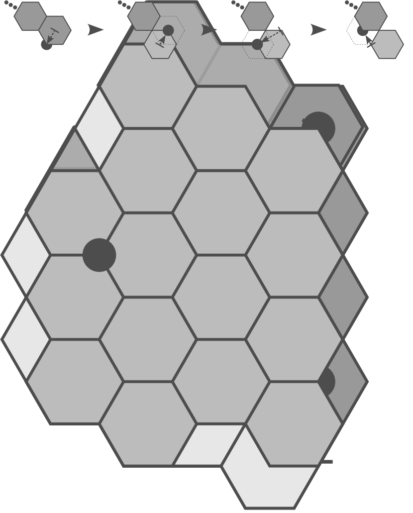
Refer to Figure 3 for an illustrative example of the algorithm in action. The algorithm initiates with the agent attempting to locate a locally westernmost column. In configurations where multiple columns share the same -coordinate and are locally westernmost, the agent prioritizes finding the northernmost among them. This is achieved by moving in the nw, sw, and n directions, prioritized in that order, until no more tile is encountered in any of these directions. Eventually the agent stops upon reaching the northernmost tiled node of some column . We refer to the steps involved in finding column as the search phase.
Subsequently, it executes the BuildPar procedure, which we describe in the following: Starting from node , the agent traverses each column in the configuration from n to s. If, during the traversal of the first column , the agent encounters either a more western column (as depicted in Figure 3(b)) or a column with the same -coordinate as to the north while moving n in the next column , it discontinues the current traversal and transitions to the search phase. Notably, in the latter case, it first fully traverses column in direction n and afterwards moves to the first column west of . This technical detail will play an important role in the runtime analysis. While traversing a column in the s direction, the agent actively looks for an empty node that violates the shape of a (partially filled) parallelogram with westernmost column . Specifically, it checks the two empty nodes immediately above (excluding column ) and below each column, as well as each empty neighbor to the east of the column. Upon finding such a violating empty node , the agent first places its carried tile at and then returns to column to retrieve the tile from . Subsequently, this exchange of tiles is termed as a tile shift from to or as shifting (the tile) from to (recall that the agent initially carries a tile that was never placed at any node). After picking up the tile at , the agent moves to an adjacent tile and transitions to the search phase again. The agent terminates at the empty node s of the easternmost column once the configuration is fully traversed without encountering any violating nodes. Any of the following conditions are sufficient for an empty node to be considered violating: (1) has a tile at n, ne and se (e.g., Figure 3(c)), (2) has a tile at s and se (e.g., Figure 3(d)) and is not n of the westernmost column (recall that we allow the parallelogram to be partially filled), (3) has a tile at nw and n (e.g., Figures 3(e), 3(f), 3(g) and 3(i)), (4) has a tile at and s (e.g., Figure 3(h)).
3.2 An Icicle Formation Algorithm


From a high-level perspective, the construction of an icicle involves the iterative transformation of a locally uppermost fragment into a parallelogram, followed by a projection of the fragment in the dsw direction. When applying the parallelogram construction algorithm in a 2D configuration, the agent can always shift the tile at the northernmost node of a locally westernmost column without violating connectivity. In a 3D configuration, the situation becomes more intricate. There are cases in which the tile at must remain in its immediate neighborhood to avoid violating connectivity. Additionally, there is a case in which the tile at cannot be moved at all unless neighboring tiles are also moved. We categorize these cases based on specific properties of node , which we define as follows:
Definition 3.1.
Let be an arbitrary tiled node. Denote by the neighborhood of (exluding ), and by its subset of only tiled nodes. Node is removable, if the tiled neighbors of are locally connected, i.e., is connected. Node is shiftable, if is disconnected and there exists a node (termed bridge node of ) for which is connected. Any node that is neither removable nor shiftable is termed unmovable.
We now state the full icicle algorithm: The agent starts in the search phase where it moves and n as long as there is a tile in any of these directions until it eventually stops at some node .
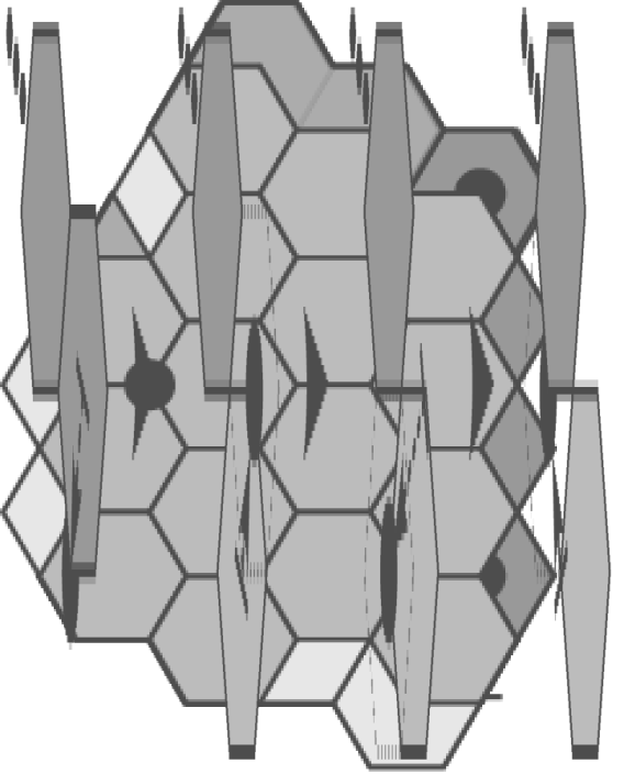
If node is removable, the parallelogram traversal procedure BuildPar is entered. There are three possible outcomes: the agent returns from the procedure after finding a more western column or some tile above, after placing a tile, or at the empty node s of the fragment’s easternmost column. In the first case, the agent transitions to the search phase. In the second case, the agent first moves back to pick up the tile at node , then moves to the next tile at s or se, and afterwards transitions to the search phase. In the third case, the current fragment forms a correctly shaped parallelogram and the agent proceeds by executing the Project procedure. During Project, each tile of the fragment is projected in the dsw direction. Starting with the easternmost column, tiles are projected columnwise from east to west and within the columns from n to s (see Figures 4(a), 4(b), 4(c), 4(d) and 4(e)). Let be the nodes of the currently projected column ordered from n to s. For each , the agent performs a tile shift from to the first empty node in direction dsw of . After picking up the last tile of the column at , the agent moves nw and continues the projection in the western neighboring column. In the special case of a degenerated parallelogram with a height of one, after picking up a tile, the agent moves sw and dnw instead (see Figure 4(f)). These additional steps ensure that connectivity is maintained during the projection. Once the last tile of the fragment is projected, the agent transitions to the search phase in the layer below.
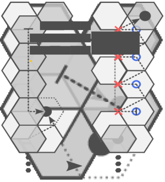
Otherwise, if the agent stops at a non-removable node , it acts according to the case distinction outlined below, prioritized in the given order (refer to Figure 5 for a graphical overview). Subsequently, the agent transitions to the search phase, concluding our algorithm.
Case 1.
Case 2.
If is a bridge node of , and at least one neighboring tile is not at dsw or se, then shift the tile from to (see Figures 5(h), 5(i), 5(j), 5(k), 5(l), 5(m), 5(n), 5(o), 5(p) and 5(q)), and move to the first tile at , or . Additionally, if is empty and both and are tiled, then traverse the next column starting at in direction s. If during that traversal a tile at or sw is encountered, then immediately transition to the search phase.
Case 3.
If the only tiled neighbors of are at dsw and se, then move se and observe node . If is empty, then shift the tile from to (see Figure 5(r)), and move to afterwards. Otherwise, if is already tiled, move back to and enter BuildPar.
Case 4.
If the only tiled neighbors of are at and ne ( is unmovable, see Figure 5(s)), then follow these steps: First, move s until some node is entered that has a neighboring tile at or de, or until there is no more tile in direction s. If has a tile at or sw, then immediately transition to the search phase. Otherwise, shift each tile in the column that is somewhere n of in direction de (including if is empty). To be precise, let be the nodes of the column ordered from s to n starting at (or if is empty). Perform a tile shift from to for each with . After the tile shift at with , move to be positioned at (to preserve connectivity). Once the final tile is picked up, move to .
Case 5.
If the only tiled neighbors of are at dnw and s (see Figure 5(t)), then proceed analogously to the previous case, with the exception that tiles at dsw are disregarded. Additionally, make the following adaptations: If no tile at or de is encountered, then project the whole column (which is a parallelogram of width one) in direction dsw. Otherwise, after performing the final tile shift in direction de, repeatedly move s (on empty nodes) and enter the first tiled node at s or se (which must exist since we did not project).
The following remarks aim to clarify the choices made in the above case distinction: In case 3, the node serves as a bridge node for ; however, the agent takes an additional step by attempting to shift the tile to . This decision stems from the fact that is not within the bounding cylinder of tiles observable from node . Similarly, in case 4, serves as a bridge node for . Although is within the bounding cylinder of observable tiles, it shares the same - and -coordinates as . It is essential to our analysis that tiles are never placed outside of the bounding cylinder, and that, except for projections, tiles consistently advance to the east or south. In case 2, the agent removes the last tile of some column and instead of immediately transitioning to the search phase, it first traverses the next column in the s direction. Similarly to the BuildPar procedure, where the agent first traverses the next column fully in direction n whenever a more northern column of the same -coordinate as is found, this additional traversal is crucial for the runtime analysis. To elaborate, if column has multiple adjacent columns to the west, then directly entering the search phase would result in repeatedly traversing the same tiles within column . However, with the additional traversal in direction s in case 2 (and in direction n in procedure BuildPar), we can ensure that each tile of is visited only a constant number of times whenever the agent does not currently perform a tile shift.
4 Analysis
Our proof structure is as follows. We first show that our algorithm complies with the connectivity constraint of the 3D hybrid model. Following this, we introduce three key definitions, termed P1–P3, each associated with some fragment of a configuration. Moving forward, we show convergence towards an icicle in two steps. First, we show that any initially connected configuration converges to a configuration containing a fragment that satisfies P1–P3. Second, we prove that the aforementioned configuration further converges to an icicle. In the following, denotes the configuration that results from the execution of BuildIcicle for steps.
Lemma 4.1.
If the agent disconnects in step , then is connected, and for all : is connected and the agent carries a tile.
Proof 4.2.
To disconnect , the agent must pick up a tile from some node in step . Note that the lemma’s statement holds trivially for step , since the agent’s position does not change by picking up a tile. Node must be a cut node w.r.t. , which implies that it is also a cut node w.r.t. , i.e., not a removable node. Hence, we can exclude procedure BuildPar, as it is only entered if node were removable. In cases 1, 2 and 3, a bridge node is tiled first, which by Definition 3.1 maintains connectivity between nodes in . Hence, we must only consider the Project procedure, and cases 4 and 5.
Consider the Project procedure. After a projection at node , the node must be tiled. Node is adjacent to , a node whose -coordinate is by one smaller, i.e., . This implies that connectivity is maintained if the parallelogram’s height is larger than one. Note that since tiles are projected from n to s, this also ensures connectivity for the potentially partially filled westernmost column. Consider the projection of a parallelogram of height one. After each tile shift the agent positions itself below the next column by moving sw and dnw. Both and are adjacent to (which must be tiled) and (which is the only node in the next column). Thereby, and are connected, and after placing the tile at in step , is connected again.
During cases 4 and 5, the agent performs tile shifts in direction de, i.e., after picking up a tile at node , must be tiled. Afterwards, the agent positions itself below the tile at n by moving ne and dnw. Similarly, and are adjacent to (which we know is tiled) and (which is shifted next) and the proof is analogous.
With the following auxiliary lemma, we show that tiles are never placed outside of the bounding cylinder .
Lemma 4.3.
If during the execution of BuildIcicle a tile is shifted from some node to some node , then there are tiled nodes with and .
Proof 4.4.
We prove the lemma by explicitly providing the nodes that have the same - and -coordinate as node , respectively. Note that or can be a valid choice, since the tile is placed at before the tile at is picked up. According to Observation 1, nodes in direction n and s have equal -coordinate, nodes in direction nw and se have equal -coordinate, and in direction une and dsw have both equal -and -coordinates.
If the tile shift is performed during the Project procedure, then must be tiled and our claim follows. If it is performed during the BuildPar procedure, then there are four cases: (1) has tiles at and se, (2) has tiles at s and se, (3) has tiles at nw and n, or (4) has tiles at and s. In each case we can choose a tiled node at n or s for , and a tiled node at nw or sw for such that our claim follows.
Any tile shift outside of these procedures is performed in one the cases 1, 2, 3, 4 and 5. Consider the tile shift where node is the northernmost node of the column considered in these cases. Node cannot have a tiled neighbor in direction or n, as otherwise the agent would not leave the search phase at . This implies that the candidates for tiled neighbors of are in directions and s. Hence, there are possible neighborhoods. The cases in which is not removable are depicted in Figure 5. For completeness, Figure 6 depicts the remaining cases. One can easily verify that is removable in each of those cases, i.e., our case distinction is complete.
In the following we provide the nodes and that satisfy our claim for each of the non-removable cases (enumerated according to Figure 5). In cases (a)–(e), and . In cases (f) and (g), and . In cases (h)–(i), (k)–(m) and (p)–(r), . In cases (j) and (n)–(o), and . Finally, in cases (s) and (t), multiple tile shifts are performed precisely from the nodes to the nodes in the given order, where is the s-most node at which a tile shift is performed, and the n-most node of the column. For each , is a valid choice, and for , . In case (s), we can simply choose for all . In case (t), the node is empty. Here, either or is a valid choice for . Note that either of the two nodes must be tiled, as otherwise no tile shift at would be performed in case (t).
For all possible tile shifts that can be performed during the execution of BuildIcicle we explicitly provided the nodes and , which concludes the lemma.
Lemma 4.5.
For each there is a tiled node with .
Proof 4.6.
Assume by contradiction, that the lemma’s statement does not hold, and let be the first step for which there is no tiled node with . Recall that the -coordinate of any node is relative to the initial minimum -coordinate in , which we defined as . Hence, it holds that and in step the agent has picked up a tile at the only node with . We again distinguish whether the tile was picked up as part of a tile shift in the procedures Project, BuildPar or in cases 1, 2, 3, 4 and 5, and lead each case to a contradiction which concludes the lemma.
First, in procedure Project, between placing a tile at some node and picking up a tile from node , the agent moves exclusively une. Observation 1 implies that , which contradicts that is the only node with .
Second, consider a tile shift from to some node that was initiated in procedure BuildPar. There are two cases: Either is the empty node s of the column that contains , or lies somewhere east of column . The former case again contradicts that is the only node with . In the latter case, there must exist a node with , which contradicts Lemma 4.3.
We want to measure the progress of tiles within the bounding cylinder towards the east and south by considering their - and -coordinates. As part of the BuildPar procedure and cases 2, 4 and 5, the -coordinate of tiles can increase when their -coordinate decreases. Although the size of the bounding cylinder cannot increase by Lemma 4.3, it may decrease. In such instances, by Lemma 4.5, the resulting bounding cylinder always aligns with the eastern side of the initial bounding cylinder . To address this, we introduce a combined representation of the - and -coordinates w.r.t. the bounding cylinder for arbitrary .
Let and be the maximum and minimum -coordinates within , and let be the height of , i.e., the cylinder’s extent along the -axis. We define the -coordinate of some node as .
Consider the following definitions, which we refer to as P1–P3, that relate to some fragment . P1 characterizes a locally uppermost fragment, P2 a fragment covering the -coordinates of all tiled nodes, and P3 a fragment wherein tiles have the shape of a parallelogram aligned along the southern, eastern, and northern sides of the bounding cylinder.
Definition 4.7.
Let be an arbitrary fragment.
-
•
P1: is a platform, if is an empty set.
-
•
P2: is covering, if for each node there is a node with .
-
•
P3: is an aligned parallelogram, if for each node it holds that for all with there is a node with .
We can now use P1–P3 to give an alternative definition of the icicle shape.
Definition 4.8.
A Configuration is an icicle, if it contains a fragment that satisfies P1–P3, and for any node it holds that .
Any tiled node that is not contained in the fragment specified in Definition 4.8, must be somewhere of , as otherwise the number of tiles would be infinite. Hence, each node is contained in a tower of tiles whose uppermost tile is contained in , and thereby Definition 4.8 is equivalent to our definition of an icicle from Section 1.4.
Subsequently, we only consider configurations in which the agent leaves the search phase at some node . This must eventually occur since moving upwards increases its -coordinate, and moving in directions sw, nw, or n increases its -coordinate. Both coordinates are bounded within any finite set of tiled nodes. To simplify notation, we use to represent the configuration where the agent leaves the search phase for the -th time.
Consider the potential function , where denotes the set of all platforms, i.e., fragments satisfying P1. We first show its monotonicity and lower bound.
Lemma 4.9.
For each it holds that , and if , then (1) no tile was shifted between step and , or (2) a fragment was projected between step and .
Proof 4.10.
By definition, holds for all initially tiled nodes . From Lemma 4.3 follows that holds for all for all . Since the number of platforms cannot be negative, follows for all , which concludes the potential’s lower bound.
We proceed by showing monotonicity. If holds, then follows trivially. Otherwise, at least one tile was shifted before leaving the search phase for the -th time. We distinguish whether a tile was shifted in Project, BuildPar or in cases 1, 2, 3, 4 and 5.
First, consider the projection of a fragment in procedure Project. For each , a tile shift from to the first empty node somewhere in direction dsw is performed. The number of platforms increases at most by one, since all nodes in are contained in the same fragment in step , which may or may not be a platform. At the same time, the number of platforms decreases precisely by one, since all nodes in are empty in step , and must be a platform in step , since only platforms are projected. Thereby, holds. Observation 1 directly implies . This concludes for the Project procedure.
Second, if a tile is shifted from node to some node in procedure BuildPar, then must be removable. This implies that the number of platforms cannot increase by picking up the tile from . It cannot increase by placing a tile at either, since must be adjacent to some node of the fragment containing . Following the columnwise traversal, is either the node s of the column containing , or it is a node located east of . In both cases, holds, concluding strict monotonicity for the BuildPar procedure.
Third, consider cases 1, 2, 3, 4 and 5. A tile is shifted from node to (case 1), to (case 2), or to (case 3). It holds that , and . Additionally, holds in cases 1, 2, 3, 4 and 5, which is easy to see by examining all possible neighborhoods of node provided in Figure 5. We further observe that case 4 is the only case in which the number of platforms can increase, and if it does, it does so by precisely one. However, at the same time at least two tiles are shifted in direction de, which decreases the potential by at least . Finally, in case 5, the agent either enters the Project procedure, as we have already analyzed in this proof, or tiles are shifted exclusively in the de direction, similar to case 2. Therefore, in each case, we have . Moreover, in the only case where holds (case 4), it follows that , i.e., the potential’s increase is compensated by its decrease such that holds in cases 1, 2, 3, 4 and 5.
Except for the Project procedure, during which is non-increasing, we have shown that is strictly decreasing, and lower bounded by zero which concludes the lemma.
In the following lemma, we show that once the agent is positioned within a fragment that satisfies P1–P3, it will remain in such a fragment. Subsequently, we use the potential and its monotonicity to prove that this configuration is eventually reached.
Lemma 4.11.
Proof 4.12.
As we will show in the next paragraph, all tiles at nodes in must have been projected between step and such that each node directly dsw of any node in is tiled in step . Let be the fragment that contains all nodes directly dsw of in step , i.e., . Since satisfies P2, there does not exist a node in with an -coordinate that was not contained in , i.e., . It follows that satisfies P2 and P3 as well. Since in step , each node in is empty, must be a platform (P1). This implies that after the projection of , the agent cannot leave to any layer above. It follows that , which concludes the lemma.
Assume that has height at least two. In the special case where is a parallelogram of height one (refer to Figure 5(r)), the agent can enter case 3 instead of the BuildPar procedure at node , and subsequently either shift the tile from to or proceed with the projection of . Note that since satisfies P2, each fragment below must also have height one, which implies (1) that the configuration is already an icicle, and (2) that no tile is ever shifted outside of case 3 and the Project procedure, such that the proof is analogous with slightly different notation. Hence, the assumption that has height at least two does not lose generality. The projection of between step and can be deduced as follows: The agent cannot leave to a layer above since is a platform (P1). Since is a covering fragment (P2), and all cases 1, 2, 3, 4 and 5 necessitate a neighboring tile below that is not covered by , it follows that the northernmost node of its westernmost column is removable and the BuildPar procedure must be entered. Lastly, since is an aligned parallelogram (P3), in the BuildPar procedure, where the agent visits all nodes of in descending order of their -coordinates, it cannot find a violating node. Consequently, the agent must proceed to the Project procedure.
Lemma 4.13.
For each there is a step such that (1) or (2) where is a fragment of configuration that satisfies P1–P3.
Proof 4.14.
Let be the fragment in which the agent leaves phase search in step , i.e., . If satisfies P1–P3, then the lemma follows directly from Lemma 4.11. Assume that does not satisfy P1–P3. If , then by Lemma 4.9 either no tile was shifted or fragment was projected between step and . The agent does not shift a tile, whenever it finds a more western column or some fragment above, in which case or holds. Given that the agent’s -coordinate can increase by at most , and its -coordinate by at most , some tile must eventually be shifted. If the tile shift takes place outside of the Project procedure, then there is nothing to prove, as the lemma directly follows from Lemma 4.9 in such cases. Therefore, for the remaining proof, we assume that each tile shift is executed as part of the Project procedure. For the sake of clarity in notation, we assume that is projected directly between step and .
The projection of can only be initiated after an execution of the BuildPar procedure. Within this procedure, the agent visits all nodes of in descending order of their -coordinates, and it does not find any empty node in the bounding box of with an -coordinate smaller than any node of . This implies that is locally an aligned parallelogram, satisfying P3 with respect to configuration . The agent also does not find a neighboring tile above, which implies that satisfies P1. Note that does not necessarily satisfy P3 globally, i.e., w.r.t. . Consequently, cannot satisfy P2, as any parallelogram that satisfies P2 must also satisfy P3.
Since does not satisfy P2, it follows that there exists a node such that for all . Given that connectivity is maintained by Lemma 4.1, there is a path from any node to in . As is a platform, the first node on that path, for which is distinct from any -coordinate in , must have a smaller -coordinate than any node in . This implies that after precisely projections, the agent must be positioned in a larger fragment, i.e., .
If, in step , is not a platform, then the series of projections carried out between steps and results in a reduction in the number of platforms, in which case the lemma follows directly. Otherwise, if is not a parallelogram in step , the next tile shift must be executed outside the Project procedure, and the lemma follows from Lemma 4.9. Finally, if is both a platform and a parallelogram but does not satisfy P2, we can once again identify a node whose -coordinate is not covered by any node of , and the process described above repeats for . The size of any fragment is upper bounded by , which implies that this process cannot repeat indefinitely. Note that distinct nodes of the same layer must have distinct -coordinates, which implies that whenever the size of the fragment at the agent’s position increases, the total number of -coordinates that are covered by that fragment also increases. Consequently, it follows that eventually, in some step , one of the following conditions holds: (1) the number of platforms decreases, (2) the agent shifts a tile outside of the Project procedure, or (3) satisfies P2.
Again, in the first two cases, . In the latter case, whenever the first two cases do not occur, P1–P2 hold as well such that the lemma follows.
The initial number of platforms is at most , and the initial -coordinate of any tiled node is at most . Hence, the initial potential is . Consequently, Lemma 4.11 and Lemma 4.13 imply that eventually the agent is positioned in a fragment satisfying P1–P3.
For the second part of our analysis, dedicated to demonstrating convergence towards an icicle, we introduce another potential function . This function is defined as the number of empty nodes within the bounding box that have a tile somewhere in the dsw direction. Formally, and .
Lemma 4.15.
Let where satisfies P1–P3. If , then .
Proof 4.16.
Let be the set from the definition of , and note that is not empty by assumption. We prove the lemma by showing that a node with exists, and that for all .
Let be a node with maximum -coordinate. Recall that is a covering fragment as per P2 and also a platform as per P1. This impilies that no node within the bounding box possesses a -coordinate larger than . Here, denotes the common -coordinate of all nodes within . Consequently, it follows that .
According to Observation 1, consecutive nodes in both the dsw and une directions share identical -coordinates, i.e., for all it holds that . For all empty nodes of -coordinate holds that is an empty node for all . Otherwise there would exist a tiled node whose -coordinate is not covered by some node of , which would contradict that satisfies P2. This observation directly implies that for every node , there exists a corresponding node such that . Combining this with the previously established relation , we can conclude that holds for all nodes .
Consider , a node within with . Given that is a node with the maximum -coordinate in , we can deduce that is a tiled node for all . The proof of Lemma 4.11 establishes that if satisfies P1–P3, then it undergoes projection between steps and . As a result of that projection, a specific tile shift is performed, precisely from node to node . Consequently, this tile shift implies that is no longer part of , which concludes the first part of the proof.
To prove that a projection cannot introduce any nodes to , we begin by considering an arbitrary node and assume, for contradiction, that . In step , as per definition of , there exists a tiled node for some . The absence of in leads to two possible cases: either (1) was not empty in step , or (2) was not tiled in step .
In the first case, since the only tiles picked up between steps and are at nodes of , we conclude that . By definition, , implying the existence of a tiled node in step with . However, in step , there cannot be a tiled node with -coordinate greater than . The fact that each node in is empty in step leads to the contradiction that, in step , there are two distinct fragments with -coordinate , violating P2.
In the second case, between steps and , a tile must have been shifted from some node to where is the first empty node dsw of node . This implies . Similar to the first case, in step , no node in has a -coordinate greater than . In step , each node in is empty, leading to the conclusion that every node in must have a -coordinate smaller than . Combining this with , we derive . This contradicts that must be the first empty node dsw of .
Both cases lead to a contradiction, implying that a node with does not exist. This completes the second part of the proof and, consequently, the lemma.
Once the agent enters a configuration where it is positioned within a fragment satisfying P1–P3, it consistently remains within such a fragment in subsequent configurations according to Lemma 4.11. By Lemma 4.13, such a configuration must eventually be reached, and by the previous lemma, our second potential is strictly monotonically decreasing afterwards. It follows that the set of empty nodes within that have a tile somewhere in the dsw direction must eventually be empty. Consequently, any tiled node within the bounding box that is not contained in the singular uppermost fragment satisfying P1–P3 must possess a neighboring tile at une. Hence, the entire configuration satisfies Definition 4.8, which is captured by the following theorem, serving as the conclusion of our analysis:
Theorem 4.17.
The sequence of configurations resulting from the execution of BuildIcicle on any initially connected configuration with converges to an icicle.
5 Termination Criteria and Runtime
Once the agent is positioned within a fragment satisfying P1–P3, it remains within such a fragment and subsequently exclusively performs projections. In the case where the configuration is already an icicle (see Definition 4.8), every tiled node in the configuration must be traversed during these projections. This condition is essential for our termination check. The agent maintains a flag term, which it flags as true upon initiating a projection. This flag only reverts to false if the agent detects any violation of Definition 4.8 during the ongoing projection, i.e., whenever a tiled node is observed for which and , where is the fragment in which the projection was initiated. Once term still holds after a projection, the agent terminates. Note that the flag is reverted, even if is tiled immediately afterwards. As an example, if a tile shift from some node to is performed as part of a projection, then node is observed before the tile is placed at . Although it is possible that the configuration is an icicle after tiling node , the agent cannot verify it during that projection, as it does not traverse node or any node dsw of .
In general, by adhering to this termination procedure, the agent consistently performs one additional projection once the configuration converges to an icicle. Since the algorithm only terminates following a projection in which it could observe all tiled nodes and only if, in this case, Definition 4.8 is satisfied, the correctness of our algorithm is established.
The algorithm’s runtime can be expressed as the sum , where accounts for all steps performed during the projection subroutine, for steps that are performed as part of some tile shift (outside of a projection), and for any remaining step. We bound each term individually by , which gives a runtime of in total.
Lemma 5.1.
The total number of steps performed during projections is .
Proof 5.2.
Consider the projection of some fragment . During that projection, the agent visits each node at most three times: at most once moving n to find the n-most node at which the projection of a column is initiated, once moving s during the projection of that column, and once to pick up the tile at after is projected. Any tiled node is visited at most twice: at most once moving dsw and at most once moving back une. In total, all tiled nodes are visited at most three times, which implies that the projection of takes steps. In the following, we show that no more than projections are performed throughout the execution.
Consider the projection of any fragment prior to the existence of a fragment that satisfies P1–P3. Note that must be a platform in order to be projected. We distinguish whether is a platform that results from the execution of case 4, in which case we call a temporary platform, or whether was already present initially, in which case we call an initial platform. There are at most initial platforms, each of which requires at most projections until the number of platforms reduces by one, e.g., if all nodes are occupied for all nodes of some initial platform and all . It follows that at most projections of initial platforms can occur. Now we consider temporary platforms. Denote the nodes whose tiles are shifted to nodes during the execution of case 4 (see Figure 5(s)). Let be the fragment that contains prior to the tile shifts, and the resulting fragments after the tile shift, i.e., . The number of platforms increases, if either is already a platform, or the nodes in with an upwards neighboring tile are all contained in or all contained in . As a result, the execution of case 4 can increase the number of platforms at most by one. W.l.o.g. let be projected before . After the projection of , all nodes in are contained in the same fragment as the nodes , and that fragment is adjacent to . This implies, that a single projection suffices to reduce the number of platforms by one whenever or is temporary. Whenever a temporary platform is created in case 4, the -coordinate of at least two tiles decreases by one. By Lemma 4.3, the -coordinate cannot be negative, which implies that it can decrease by at most for any tile. Thereby, case 4 can be executed at most times, which adds temporary platforms and thereby additional projections. This concludes that the total number of projections prior to the existence of a fragment that satisfies P1–P3 is .
Once a fragment that satisfies P1–P3 exists, at most additional projections are required before the configuration is an icicle, i.e., after at most additional projections the agent terminates. This follows directly from the observation that the bounding boxes of tiled nodes before and after the projections are completely disjoint, and since we cannot create any node that violates the shape of the icicle during those projections as shown in the proof of Lemma 4.15.
We have shown that projections are performed in total, each of which requires steps. From this, the lemma follows directly.
Lemma 5.3.
Let be the first step following an arbitrary projection, and the next step in which a projection is initiated. Between step and at most steps are performed outside of tile shifts, and any tile shift from some node to takes steps.
Proof 5.4.
We begin by addressing the latter statement of the lemma. Consider the number of steps performed during a tile shift from some node to . The BuildPar procedure lets the agent visit nodes in decreasing order of their -coordinates. Nodes with are visited at most twice before placing a tile at node , and at most twice again before picking up the tile at . Additionally, two steps are required for both tile placement and retrieval. Consequently, the claim that the tile shift takes steps directly follows for tile shifts during procedure BuildPar.
Moving on to cases 1, 2 and 3, a single tile is shifted in the directions , or , requiring steps. However, as per Observation 1, the -coordinate of the tile decreases by one, implying a reduction in the tile’s -coordinate, where is the height of the bounding cylinder of . This observation becomes useful below, where we use the difference between the performed steps and the reduction of the -coordinate by to account for the additional movement that follows case 2. In the case of tile shifts in cases 4 and 5, the agent follows a two-step process: initially traversing tiles of the column in the s direction and subsequently shifting all tiles in the de direction. The proportional number of steps per shifted tile is constant which concludes the latter statement of the lemma.
Next, consider any move between step and that is not part of some tile shift. In step , the agent repeatedly moves or n in the search phase. Notably, none of these moves can decrease its -, -, or -coordinate. Consequently, after steps, the agent must leave the search phase at some northernmost node of some column .
Subsequently, whenever the agent finds a column with the same -coordinate as to the north while moving n in the column east of , it enters the northernmost adjacent column west of and transitions to the search phase. In such instances, no tile in column was visited between step and . Consequently, the tiles in column that were visited in order to find did not contribute to the steps of the initial search phase, allowing us to include the additional steps taken to visit in the overall count.
Apart from the initial search phase and the first visits to more northern columns of equal -coordinate, the agent moves without shifting a tile in the following scenarios:
- 1.
-
2.
Whenever it encounters a more western column (in the same procedure and cases).
-
3.
After picking up a tile at , where , i.e., after removing the last tile of column . In this case, the agent moves an additional steps within the eastern neighboring column of .
-
4.
After picking up a tile at where , i.e., is not the last tile of column . In this case, the agent moves a single step s.
First, we consider case 1, where the agent discovers an upper layer. Notably, outside of the projection subroutine, the agent never moves to a layer below. Given our assumption that no projection occurs between step and , it follows that each time the agent moves to an upper layer in the BuildPar procedure or in cases 4 and 5, the tiles visited in that particular execution of BuildPar or cases 4 and 5 are not revisited until after step . This implies that all tiles can be visited only a constant number of times over all these executions, thereby giving an overhead of steps for case 1.
Similarly, excluding tile shifts, the agent exclusively moves to the east after completely removing all tiles from a column . We argue that in such instances, the column east of cannot have any more neighboring tiles to the west. Moreover, except for the initial search phase in step , more western columns are only found following the additional column traversal in case 2. Afterwards, we account for the overhead steps resulting from that additional column traversal using the constant runtime for the tile shift in case 2, as explained in the first paragraph of this proof. Consequently, case 2 does not introduce any additional steps that are not already accounted for by the constant runtime tile shifts.
To elaborate further, let’s focus on case 3. There are two scenarios in which the agent picks up the tile at the last node of some column . Firstly, during the execution of case 2, after which the eastern neighboring column of is traversed in the s direction, either leading the agent to a western neighboring column of after steps, or positioning it at the northernmost tile of column if no such column is found. We can count the steps that follow the execution of case 2 to the constantly many steps required for case 2 (which we have shown in the first paragraph of this proof). The second scenario is after shifting a tile in the BuildPar procedure. In this case, node must be the southernmost node of column . We can further distinguish two cases: (1) the tile at is shifted to the empty node that is north of column , or (2) the tile is shifted to some node further east than column . Note that in both cases, cannot have any further neighboring column to the west, as otherwise, the agent would not have fully traversed column in the n direction. In the former case, the tile at node is shifted to some node afterward. Node is either located east of column or directly south of . In either case, it holds that , and we can count the steps to the subsequent tile shift from to . In the latter case, we can count the steps directly to the tile shift from to , as in this case .
To summarize, each overhead step resulting from case 3 is effectively covered by the constant runtime of the tile shift in case 2. Whenever a more western column is found outside of the additional column traversal that follow case 2, that column is visited for the first time between step and , in which case we can count the steps necessary to reach that column to the initial steps in phase search. Hence case 2 does not produce additional overhead.
Finally, we simply account for the single step from node to node following case 4 as part of the preceding tile shift.
As established in the proof of Lemma 5.1, a total of projections are performed., which together with Lemma 5.3 implies that . The -coordinate of any tile is at most , non-increasing, and cannot be negative (see Lemmas 4.9 and 4.3). Together with Lemma 5.3, each tile contributes steps to , which implies that . This concludes our final theorem:
Theorem 5.5.
BuildIcicle has a runtime of steps.
6 Experimental Analysis
While our algorithm matches the runtime bound of the 3D line formation algorithm [15], the icicle offers distinct advantages over the line. The diameter of an icicle can be as low as , whereas a line consistently maintains a diameter of . Unfortunately, our algorithm does not improve the diameter if the initial configuration already closely resembles a line. On the other hand, we conjecture that if the initial diameter is as low as (which is the best case in 3D), then our algorithm can only increase the diameter by a factor of . We support our conjecture with the following simulation results on configurations where initially all tiles are contained in a sphere of radius .
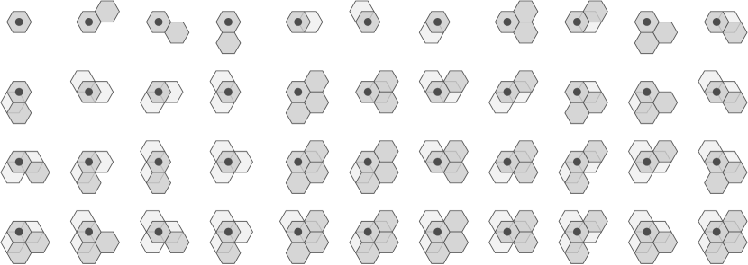
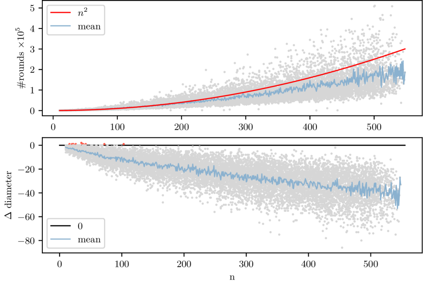
We conducted a total of 12,250 simulations using the icicle formation algorithm on random configurations. For each value of within the range , we sampled 25 random configurations as follows: empty nodes were repeatedly chosen uniformly at random within a sphere of radius , and a tile was placed on each selected node until a connected component of tiled nodes with a size of at least was formed. Subsequently, any tile outside of that component was removed, the agent was placed at a randomly chosen tile within the component, and the algorithm was simulated until termination. We measured the runtime as well as the difference in diameter, which are plotted in Figure 7.
Due to the nature of the described random generation process, configurations of size larger than 500 were also sampled, although less frequently. Specifically, we observed an average sampling rate of approx. 24.4 configurations for sizes at most 450, contrasting with approx. 15.4 configurations for sizes exceeding 450. This discrepancy contributes to the noticeable increase in variance as the configuration size approaches the 500 threshold.
The runtime stays below the proven upper bound of , and notably, it remains well in the vicinity of . This can be attributed to the initial close packing of all tiles in our random configurations. Additionally, instances where the diameter increases (indicated by red dots above the -axis) are infrequent, and their occurrence diminishes as the configuration size increases. This trend implies a general decrease in diameter in the average case.
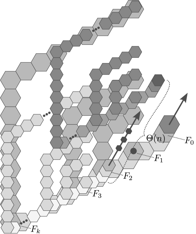
In the following, we present what we believe to be the worst-case configuration. Consider the configuration depicted in Figure 8(a) that consists of three layers. The middle layer contains fragments ordered from east to west, where each has size and the agent’s initial position is . It further contains a fragment of size one east of the agent’s initial position. Observe that the bounding box of contains no node from for any with . It follows that the agent builds and projects parallelograms in the order . Since the bounding box of contains for all , it further follows that tiles are projected from in direction dsw. Only then, the agent traverses the lower layer and eventually finds fragment where it moves further upwards. Now consider the configuration that consists of copies of in direction une (see Figure 8(b)). That configuration has diameter initially. Throughout the icicle formation algorithm, some tile at node is projected times, which implies that the resulting icicle has depth and thereby also diameter .

7 Future Work
In this work, we introduced an algorithm capable of transforming any initially connected configuration into an icicle within steps, complemented by proofs of correctness and runtime analysis. While our algorithm’s experimental results are promising, future work should include a formal proof to substantiate the claimed upper bound of on the increase in diameter. Additionally, the adaptability of our algorithm to the multi-agent case poses an intriguing challenge for future investigation. Given that the algorithm comprises distinct phases potentially executed in an interleaved manner, addressing its integration into a multi-agent framework presents a non-trivial research direction.
References
- [1] M. Akter, J. J. Keya, K. Kayano, A. M. R. Kabir, D. Inoue, H. Hess, K. Sada, A. Kuzuya, H. Asanuma, and A. Kakugo. Cooperative cargo transportation by a swarm of molecular machines. Science Robotics, 7(65):eabm0677, 2022. URL: https://www.science.org/doi/abs/10.1126/scirobotics.abm0677, arXiv:https://www.science.org/doi/pdf/10.1126/scirobotics.abm0677, doi:10.1126/scirobotics.abm0677.
- [2] Dana Angluin, James Aspnes, Zoë Diamadi, Michael J. Fischer, and René Peralta. Computation in networks of passively mobile finite-state sensors. Distributed Computing, 18(4):235–253, Mar 2006. doi:10.1007/s00446-005-0138-3.
- [3] Manuel Blum and Dexter Kozen. On the power of the compass (or, why mazes are easier to search than graphs). In 19th Annual Symposium on Foundations of Computer Science (sfcs 1978), pages 132–142, 1978. doi:10.1109/SFCS.1978.30.
- [4] Jie Chao, Jianbang Wang, Fei Wang, Xiangyuan Ouyang, Enzo Kopperger, Huajie Liu, Qian Li, Jiye Shi, Jun hu, Lianhui Wang, Wei Huang, Friedrich Simmel, and Chunhai Fan. Solving mazes with single-molecule dna navigators. Nature Materials, 18, 03 2019. doi:10.1038/s41563-018-0205-3.
- [5] Huiling Chen, Chenyang Li, Majdi Mafarja, Ali Asghar Heidari, Yi Chen, and Zhennao Cai. Slime mould algorithm: a comprehensive review of recent variants and applications. International Journal of Systems Science, 54(1):204–235, 2023. arXiv:https://doi.org/10.1080/00207721.2022.2153635, doi:10.1080/00207721.2022.2153635.
- [6] G.S. Chirikjian. Kinematics of a metamorphic robotic system. In Proceedings of the 1994 IEEE International Conference on Robotics and Automation, pages 449–455 vol.1, 1994. doi:10.1109/ROBOT.1994.351256.
- [7] Zahra Derakhshandeh, Shlomi Dolev, Robert Gmyr, Andréa W. Richa, Christian Scheideler, and Thim Strothmann. Amoebot - a new model for programmable matter. In Proceedings of the 26th ACM Symposium on Parallelism in Algorithms and Architectures, SPAA ’14, page 220–222, New York, NY, USA, 2014. Association for Computing Machinery. doi:10.1145/2612669.2612712.
- [8] Zahra Derakhshandeh, Robert Gmyr, Andréa W. Richa, Christian Scheideler, and Thim Strothmann. An algorithmic framework for shape formation problems in self-organizing particle systems. In Proceedings of the Second Annual International Conference on Nanoscale Computing and Communication, NANOCOM’ 15, New York, NY, USA, 2015. Association for Computing Machinery. doi:10.1145/2800795.2800829.
- [9] Zahra Derakhshandeh, Robert Gmyr, Andrea W. Richa, Christian Scheideler, and Thim Strothmann. Universal shape formation for programmable matter. In Proceedings of the 28th ACM Symposium on Parallelism in Algorithms and Architectures, SPAA ’16, page 289–299, New York, NY, USA, 2016. Association for Computing Machinery. doi:10.1145/2935764.2935784.
- [10] Giuseppe A. Di Luna, Paola Flocchini, Nicola Santoro, Giovanni Viglietta, and Yukiko Yamauchi. Shape formation by programmable particles. Distrib. Comput., 33(1):69–101, feb 2020. doi:10.1007/s00446-019-00350-6.
- [11] Pierre Fraigniaud, David Ilcinkas, Guy Peer, Andrzej Pelc, and David Peleg. Graph exploration by a finite automaton. In Jiří Fiala, Václav Koubek, and Jan Kratochvíl, editors, Mathematical Foundations of Computer Science 2004, pages 451–462, Berlin, Heidelberg, 2004. Springer Berlin Heidelberg.
- [12] Robert Gmyr, Kristian Hinnenthal, Irina Kostitsyna, Fabian Kuhn, Dorian Rudolph, and Christian Scheideler. Shape recognition by a finite automaton robot. In Igor Potapov, Paul Spirakis, and James Worrell, editors, 43rd International Symposium on Mathematical Foundations of Computer Science (MFCS 2018), volume 117 of Leibniz International Proceedings in Informatics (LIPIcs), pages 52:1–52:15, Dagstuhl, Germany, 2018. Schloss Dagstuhl–Leibniz-Zentrum fuer Informatik. URL: http://drops.dagstuhl.de/opus/volltexte/2018/9634, doi:10.4230/LIPIcs.MFCS.2018.52.
- [13] Robert Gmyr, Kristian Hinnenthal, Irina Kostitsyna, Fabian Kuhn, Dorian Rudolph, Christian Scheideler, and Thim Strothmann. Forming tile shapes with simple robots. Natural Computing, 19(2):375–390, Jun 2020. doi:10.1007/s11047-019-09774-2.
- [14] Amelie Heuer-Jungemann and Tim Liedl. From dna tiles to functional dna materials. Trends in Chemistry, 1(9):799–814, 2019. URL: https://www.sciencedirect.com/science/article/pii/S258959741930190X, doi:10.1016/j.trechm.2019.07.006.
- [15] Kristian Hinnenthal, Dorian Rudolph, and Christian Scheideler. Shape formation in a three-dimensional model for hybrid programmable matter. In Proc. of the 36th European Workshop on Computational Geometry (EuroCG 2020), 2020.
- [16] Frank Hoffmann. One pebble does not suffice to search plane labyrinths. In International Symposium on Fundamentals of Computation Theory, 1981.
- [17] Ferran Hurtado, Enrique Molina, Suneeta Ramaswami, and Vera Sacristán. Distributed reconfiguration of 2d lattice-based modular robotic systems. Autonomous Robots, 38(4):383–413, Apr 2015. doi:10.1007/s10514-015-9421-8.
- [18] Irina Kostitsyna, David Liedtke, and Christian Scheideler. Universal coating in the 3d hybrid model, 2023. arXiv:2303.16180.
- [19] Irina Kostitsyna, Christian Scheideler, and Daniel Warner. Fault-tolerant shape formation in the amoebot model. In 28th International Conference on DNA Computing and Molecular Programming (DNA 28), pages 9:1–9:22, 2022. DBLP License: DBLP’s bibliographic metadata records provided through http://dblp.org/ are distributed under a Creative Commons CC0 1.0 Universal Public Domain Dedication. Although the bibliographic metadata records are provided consistent with CC0 1.0 Dedication, the content described by the metadata records is not. Content may be subject to copyright, rights of privacy, rights of publicity and other restrictions. doi:10.4230/LIPIcs.DNA.28.9.
- [20] Guannan Li, David St-Onge, Carlo Pinciroli, Andrea Gasparri, Emanuele Garone, and Giovanni Beltrame. Decentralized progressive shape formation with robot swarms. Autonomous Robots, 43(6):1505–1521, Aug 2019. doi:10.1007/s10514-018-9807-5.
- [21] Hao Li, Jing Gao, Lei Cao, Xuan Xie, Jiahui Fan, Hongda Wang, Honghui Wang, and Zhou Nie. A dna molecular robot autonomously walking on the cell membrane to drive the cell motility. Angewandte Chemie International Edition, 60, 09 2021. doi:10.1002/anie.202108210.
- [22] Nooshin Nokhanji, Paola Flocchini, and Nicola Santoro. Fully dynamic line maintenance by hybrid programmable matter. In 2022 IEEE International Parallel and Distributed Processing Symposium Workshops (IPDPSW), pages 486–495, 2022. doi:10.1109/IPDPSW55747.2022.00087.
- [23] Andreas Padalkin, Manish Kumar, and Christian Scheideler. Shape formation and locomotion with joint movements in the amoebot model. ArXiv, abs/2305.06146, 2023. URL: https://api.semanticscholar.org/CorpusID:258587865.
- [24] Matthew J. Patitz. An introduction to tile-based self-assembly and a survey of recent results. Natural Computing, 13(2):195–224, Jun 2014. doi:10.1007/s11047-013-9379-4.
- [25] Tom Peters, Irina Kostitsyna, and Bettina Speckmann. Fast reconfiguration for programmable matter. In Rotem Oshman, editor, 37th International Symposium on Distributed Computing, DISC 2023, Leibniz International Proceedings in Informatics, LIPIcs, pages 27:1–27:21, October 2023. doi:10.4230/LIPIcs.DISC.2023.27.
- [26] Ning Tan, Abdullah Aamir Hayat, Mohan Rajesh Elara, and Kristin L. Wood. A framework for taxonomy and evaluation of self-reconfigurable robotic systems. IEEE Access, 8:13969–13986, 2020. doi:10.1109/ACCESS.2020.2965327.
- [27] Pierre Thalamy, Benoît Piranda, and Julien Bourgeois. A survey of autonomous self-reconfiguration methods for robot-based programmable matter. Robotics and Autonomous Systems, 120:103242, 2019. URL: https://www.sciencedirect.com/science/article/pii/S0921889019301459, doi:10.1016/j.robot.2019.07.012.
- [28] Anupama J. Thubagere, Wei Li, Robert F. Johnson, Zibo Chen, Shayan Doroudi, Yae Lim Lee, Gregory Izatt, Sarah Wittman, Niranjan Srinivas, Damien Woods, Erik Winfree, and Lulu Qian. A cargo-sorting dna robot. Science, 357(6356):eaan6558, 2017. URL: https://www.science.org/doi/abs/10.1126/science.aan6558, arXiv:https://www.science.org/doi/pdf/10.1126/science.aan6558, doi:10.1126/science.aan6558.
- [29] Thadeu Tucci, Benoît Piranda, and Julien Bourgeois. A distributed self-assembly planning algorithm for modular robots. In Proceedings of the 17th International Conference on Autonomous Agents and MultiAgent Systems, AAMAS ’18, page 550–558, Richland, SC, 2018. International Foundation for Autonomous Agents and Multiagent Systems.
- [30] Jennifer E. Walter, Jennifer L. Welch, and Nancy M. Amato. Distributed reconfiguration of metamorphic robot chains. Distributed Computing, 17(2):171–189, Aug 2004. doi:10.1007/s00446-003-0103-y.
- [31] Hanlin Wang and Michael Rubenstein. Shape formation in homogeneous swarms using local task swapping. IEEE Transactions on Robotics, 36(3):597–612, 2020. doi:10.1109/TRO.2020.2967656.
- [32] Justin Werfel, Kirstin Petersen, and Radhika Nagpal. Designing collective behavior in a termite-inspired robot construction team. Science, 343(6172):754–758, 2014. URL: https://www.science.org/doi/abs/10.1126/science.1245842, arXiv:https://www.science.org/doi/pdf/10.1126/science.1245842, doi:10.1126/science.1245842.
- [33] Damien Woods, Ho-Lin Chen, Scott Goodfriend, Nadine Dabby, Erik Winfree, and Peng Yin. Active self-assembly of algorithmic shapes and patterns in polylogarithmic time. In Proceedings of the 4th Conference on Innovations in Theoretical Computer Science, ITCS ’13, page 353–354, New York, NY, USA, 2013. Association for Computing Machinery. doi:10.1145/2422436.2422476.
Appendix A Deferred Pseudocode
The pseudocode for the 2D parallelogram formation algorithm, as detailed in Section 3.1, is given by Algorithm 1. Specifically, lines 12–34 within Algorithm 1 describe the BuildPar procedure, utilized by both the parallelogram and icicle formation algorithms. Note that the checks for tiles above (lines 13–14) can be disregarded in the 2D setting, as they only become relevant in the icicle formation algorithm. The Project procedure is given in Algorithm 3, and the full icicle formation algorithm in Algorithm 2. Whenever multiple directions of movement are specified, their precedence is implicit in the provided order.
In Algorithm 1, the agent traverses a column in the s direction in lines 12–21 and the next column in the n direction in lines 26–31. Following the check for whether the empty node above the next column should be tiled (line 32), the agent recursively executes BuildPar starting at the n-most node of the next column (line 33). The procedure may return with the agent being in various states, such as positioned on a tiled or empty node, with or without a tile. In the main loop of the algorithm, BuildPar is executed repeatedly, and distinctions between these states are made to either terminate (line 4), retrieve the tile at which BuildPar was previously entered (lines 5–11), or enter the search phase (line 2).
In Algorithm 2, lines 16–22 are dedicated to handling case 2, where a tile is shifted in the de direction to maintain connectivity. Lines 23–29 cover case 4, and lines 30–40 cover case 5. These cases involve shifting multiple tiles of a column in the de direction. For concise pseudocode, the handling of case 1 is delegated to the BuildPar procedure. This is because, in that procedure, is tiled in that particular case. Additionally, within this context, we have integrated the check for a tile at from case 3 (refer to lines 4–-5).