Can We Improve Channel Reciprocity via Loop-back Compensation for RIS-assisted Physical Layer Key Generation
Abstract
Reconfigurable intelligent surface (RIS) facilitates the extraction of unpredictable channel features for physical layer key generation (PKG), securing communications among legitimate users with symmetric keys. Previous works have demonstrated that channel reciprocity plays a crucial role in generating symmetric keys in PKG systems, whereas, in reality, reciprocity is greatly affected by hardware interference and RIS-based jamming attacks. This motivates us to propose LoCKey, a novel approach that aims to improve channel reciprocity by mitigating interferences and attacks with a loop-back compensation scheme, thus maximizing the secrecy performance of the PKG system. Specifically, our proposed LoCKey is capable of effectively compensating for the CSI non-reciprocity by the combination of transmit-back signal value and error minimization module. Firstly, we introduce the entire flowchart of our method and provide an in-depth discussion of each step. Following that, we delve into a theoretical analysis of the performance optimizations when our LoCKey is applied for CSI reciprocity enhancement. Finally, we conduct experiments to verify the effectiveness of the proposed LoCKey in improving channel reciprocity under various interferences for RIS-assisted wireless communications. The results demonstrate a significant improvement in both the rate of key generation assisted by the RIS and the consistency of the generated keys, showing great potential for the practical deployment of our LoCKey in future wireless systems.
Index Terms:
Physical Layer Security, Jamming Attack, Reconfigurable Intelligent SurfaceI Introduction
Due to the openness of wireless channels and the continuous development of attack methods, severe security problems faced by wireless communication have become increasingly prominent[1]. According to research by technology company McAfee, millions of malicious Wi-Fi attacks occur every day, potentially leading to serious privacy breaches. Traditional symmetric encryption requires the pre-distribution of keys between each communicator[2], which becomes extremely complex and impractical in Internet of Things (IoT) scenarios with a huge number of terminal equipment. The goal of physical layer key generation (PKG) is to explore the endogenous security mechanism of wireless communication[3] by using the channel inherent characteristics such as time-variability[4] and channel reciprocity[5], to provide lightweight encryption. The natural properties of wireless channels make PKG have the unique advantages of low cost and high speed in solving distribution and renewal of secret keys.
However, the non-obvious Doppler effect in the quasi-static scenario of the IoT leads to slow channel change[6], significantly degrading the key generation rate (KGR). In recent years, Reconfigurable Intelligent Surface (RIS) has been a new technology that can adjust electromagnetic waves, to customize the wireless propagation environment [7]. Thanks to the characteristics of passive elements and low hardware cost, RIS-assisted wireless communication systems had been widely studied. A closed expression for the upper bound of KGR was derived in [8], which showed the relation of KGR to the number of RIS elements, correlation coefficient, pilot length, etc. Lu et.al[9] discussed how to maximize KGR by using channel state information (CSI) to dynamically adjust the open position of RIS components. It was verified in [10] that KGR with RIS assistance can be increased by 197.5% compared with the relay-assisted scheme. RIS can also facilitate PKG in mmwave system [11] or vehicle-to-vehicle (V2V) communications[12].
The above studies consider how to minimize the effect of passive eavesdropping. However, the possibility of RIS being attacked by malicious external attackers remains under-explored. Normal jamming attacks in PKG expressed by sending interference signals to the effective frequency of the channel detection[13]. Specifically, RIS-jamming is represented by Mallory alienating the RIS reflection matrix of upstream and downstream channels[14]. If RIS applies a random configuration at an update rate higher than the channel sampling rate, the difference in CSI reciprocity results in unsuccessful key negotiation. Lyu et.al[15] proposed the use of RIS as a green jammer to attack communications without using any internal energy, Hu et.al[16] proposed an attack strategy based on RIS and a multipath detection separation scheme based on a broadband system, but the randomness enhancement brought by RIS cannot be used in the key generation process. Unlike traditional jamming attacks, RIS jamming attacks do not emit interference signals, but reflect interference signals, so the location of ”Eve” is difficult to reveal, and traditional countermeasures based on position detection[17] will be ineffective. What’s more, the reason for the non-reciprocity of CSI in Time Division Duplexing (TDD) systems may also be caused by hardware fingerprint interference[18] in practical systems. Current research mainly uses pre-coding techniques to compensate for non-reciprocity, which requires a complex learning process and is not suitable for key generation scenarios that require the ability to obtain channel information in real time.
Therefore, our paper considers the perspective of channel reciprocity compensation. We put forward LoCKey, a novel scheme that can not only remove non-reciprocity caused by interference but also apply the randomness brought by RIS to improve the key generation rate. The main contributions of this paper can be summarized as follows:
We propose LoCKey, a novel channel compensation method that aims to improve the reciprocity of the RIS-assisted physical layer key generation. Our proposed LoCKey can facilitate the rapid changes in the phase of RIS to manipulate the up-downward channels.
We introduce the overall process of the proposed LoCKey. We also present a theoretical analysis to show how LoCKey improves the channel reciprocity, aiming to effectively mitigate hardware interference and RIS-based jamming attacks.
Experiments show the superiority of our method compared to existing loop-back schemes and non-loop-back ones.
II System Model
II-A General PKG Procedure
Channel Measurement
Alice and Bob send pilot frequency to the peer end, and generate a random key source by probing some characteristics of the channel, e.g. received signal strength(RSS), CSI, channel phase response, and channel multipath delay. In our research, we adopt CSI as the key source.
Quantization
The communication parties convert the measured value of the channel into a bit sequence of 0 and 1. We use 2-bit gray code quantization[19] because there is only a 1-bit difference between adjacent code words, which can effectively limit the inconsistency rate.
Information Reconciliation
Discard or correct the differences between key bit streams caused by device differences or additive noise, reducing the inconsistency rate. The common methods are the Cascade method, error-correcting codes, and polar code[20].
Privacy Amplification
The sequence after information reconciliation is mapped to produce a shorter random key, exponentially reducing the leaked information to the eavesdropper. The cryptographic Hash algorithms (Digest algorithms) are usually used for privacy amplification[21], such as MD5, SHA256, etc.
As our paper researches the performance of our channel compensation method brought to the key generation rate and bit difference rate, we focus mostly on the Channel Measurement step and Quantization step.
II-B Our RIS-assisted PKG model
We consider a general RIS-assisted PKG system shown in Fig. 1. We suppose two different frequency bands (BAND 1 and BAND 2), and the transceiver can selectively turn on or off several subcarriers for each transmission to transmit through different bands, which is suitable for TDD systems with multi-carrier modulation.
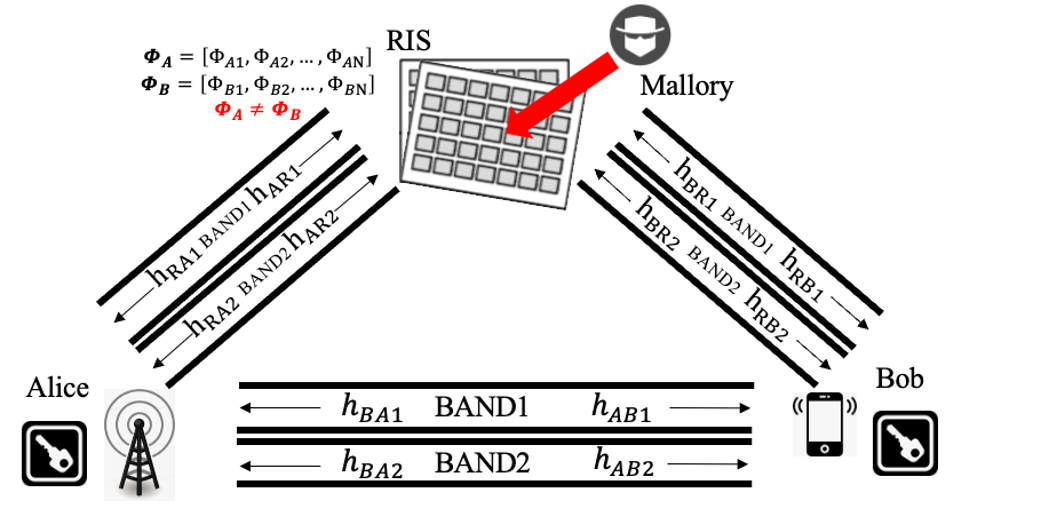
As Fig. 1 shows, single-antenna-equipped legitimate transceivers Alice and Bob take turns to transmit OFDM symbols within the coherence time during channel probing stage, where is the number of subcarriers. A RIS consisting of reflecting units is used for channel randomness improvement, assuming that all units are independent, and the status value can be set to “on” or “off” by the controller. We change the phase shift matrix in real time, where denotes the random phase shift corresponding to each RIS unit. Unavoidable hardware deviation interference -which we write as , where is the transmission direction- is a factor that causes CSI non-reciprocity.
The received signal strength (RSS) on both sides and can be written as follows, where denote the BAND used for transmission, could be seen as additive white Gaussian noise (AWGN) of each transmission.
| (1) | |||
By using the least square (LS) channel estimation method to RSS values, the CSI values at Alice and Bob could be expressed as follows, mentioned that the RIS-cascaded channel can be written as the multiplication of two sub-channels through RIS, i.e. , . In the calculation process, we write , .
| (2) | |||
RIS active jamming attack aims at disrupting the key establishment process between Alice and Bob by adjusting the RIS reflection matrices. A malicious external attacker Mallory launches active jamming by randomly changing the RIS reflection matrices in the upward and downward RIS-induced link, causing . As long as the update rate of RIS configurations is higher than the channel sampling rate, the observed CSI of RIS-induced links appear to be different, therefore destroying the total channel reciprocity. Note that the RIS matrix after being attacked will change randomly over time, while the hardware deviation is a constant value.
III Our LoCKey Scheme
III-A Scheme Flowchart
Under our attacked-RIS PKG model, we propose the LoCKey Transmission Scheme shown in Fig. 2, in order to strengthen the reciprocity of the CSI values:
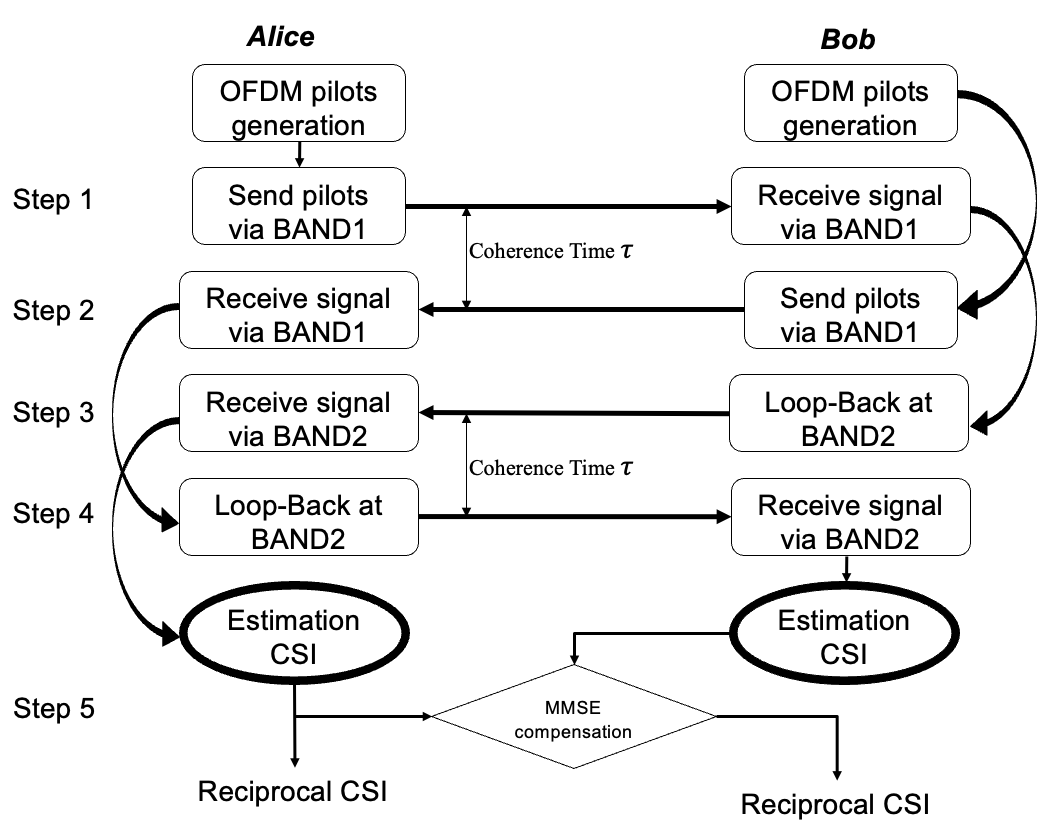
Step 1: Alice first sends a common OFDM pilot signal to Bob through BAND 1.
Step 2: Bob sends a pilot signal to Alice through BAND 1. The period between Step 1 and Step 2 is a coherence time .
Step 3: After the first round of channel measurements, Bob sends the signal received in Step 1 out through frequency BAND 2 at time , and Alice can receive the loop signal.
Step 4: Alice sends the signal received in Step 2 out through BAND 2, and Bob receives the loop signal. The period between Step 3 and Step 4 is a coherence time .
Step 5: In this module, we measure the error between the actual measured value at Bob in Step 4 and the predicted value at Alice in Step 3, then minimize the MSE of the prediction by reasonable selection of the complex value scalar.
Step 1 to 2 is the classical TDD process, and Step 3 to 4 is the added loop-back process for the PKG purpose, and Step 5 is our channel reciprocity enhanced module. Therefore, the whole transmission scheme is called as LoCKey scheme.
III-B Scheme Description
Channel changes between measurements in TDD systems are difficult to model accurately, so we assume that the change of CSI is continuously integrable for simplicity. Considering the selection of frequency bands , we define the sub-channels CSI performance under different frequency bands as follows:
| (3) |
At Step 1 of our LoCKey scheme, the received CSI by Bob from Alice is expressed by:
| (4) |
The legitimate parties send the pilot signal only once within each coherence time , then they receive the pilot signal and estimate the channel. It is assumed that the channels in coherence time remain constant and the legitimate channels satisfy perfect reciprocity:
| (5) |
Therefore in Step 2, the received CSI by Alice from Bob after a channel detection turn can be presented as follows by using the channel reciprocity equation in (5):
| (6) | ||||
After the first round of channel measurements, by sending the loop-back CSI in Step 1 to Step 3, we get a mutual CSI of the two frequency bands at Alice:
| (7) | ||||
And by sending the loop-back CSI in Step 2 to Step 4, we get a mutual CSI at Bob, also using the channel reciprocity equation in (5):
| (8) | ||||
We adopt and as key source for the future secret key generation steps. From the above two equations, we can see that the non-reciprocity brought by hardware deviation is eliminated, by sharing common randomness of cross multiplication .
But as we see, the influence of RIS-jamming still exists because the manipulated RIS matrix and are unpredictable and independent due to the malicious attacking of Mallory.
That’s why we introduce Step 5, an MMSE compensation module. In order to compensate for the imperfect channel reciprocity, the transmitter needs to predict the wireless channel that would be experienced by the receiver, particularly the channel estimation values that would be obtained by the receiver. The prediction follows the MMSE prediction methodology, where is a complex-valued scalar for the channel prediction of the subcarrier.
| (9) |
The error between the actual measured value at Bob and the predicted value at Alice in Step 3 is expressed as by calculating the error between the actual measured value at Bob when the subcarrier is sent after Step 4. We consider that here for the ease of calculation.
| (10) | ||||
The mean squared error (MSE) of the channel prediction can then be derived as , then the MSE of the prediction is minimized by a reasonable selection of the complex value scalar representing the subcarrier of the channel prediction, i.e. . After Step 5, the non-reciprocal channels caused by RIS-jamming can be adjusted for recovery.
III-C Performance Analysis
In this section, we verify the above architecture by calculating the correlation coefficient between the channel estimation values. The correlation coefficient between two random variables X and Y can be calculated by the following formula:
| (11) | ||||
where denotes the expectation operator.
Note that all sub-channels follow the Gaussian distribution, i.e. , and the background additive white gaussian noise (AWGN) is expressed by . The uncorrelated RIS matrix expressed by and , where and are unmatched random values in the range of , and is uniformly distributed between .
Therefore, after Step 1 and Step 2, the correlation coefficient between and can be expressed by:
| (12) | ||||
Whereas , , a and b are the statistical mean of RIS matrix in up-downward links. In the above equations, we assume that for all sub-channels for better analysis of our target.
Taking the same approach, the correlation coefficient after Step 3 and Step 4 between the partly randomness-shared and is:
| (13) | ||||
We apply an MMSE predictor in (9) to compensate for the decorrelation brought by manipulated RIS. Our goal is to minimize the mean squared error (MSE) of the channel prediction and the original channel estimation, therefore the MSE of channel prediction can then be derived as:
| (14) | ||||
Let , it can be easily inferred from the definition of that the adjusted correlation factor after Step 5 between the reciprocal CSI and could be concluded as . The derivatives of concerning both p and q must be zero, for the squared error to be minimized with respect to . Therefore:
| (15) | ||||
and
| (16) | ||||
Then the prediction scalar for the subcarrier can be derived as:
| (17) |
IV Simulation Results
In order to verify the performance of the proposed LoCKey scheme and compare it with the classical loop-back scheme and non loop-back scheme, extensive simulation experiments are carried out based on MATLAB in this section.
We conduct experiments on an OFDM transceiver model and used the Least Square channel estimation method, and the basic simulation parameters are given in Table 1, which are recommended by the ITU Vehicular Type A channel model. The effect of hardware finger-print is modeled as different fixed constant values on both sides of transceivers.
| Parameters | Value |
| OFDM symbol length | 64 |
| Subcarrier frequency spacing 1 | 15 KHz |
| Subcarrier frequency spacing 2 | 20 KHz |
| iFFT Size | 64 |
| number of symbols | 500 |
| modulation mode | QPSK |
| cyclic prefix length | 16 |
| pilot interval | 5 |
| iteration number | 100 |
| maximum doppler shift | 5Hz |
| multipath delay | [0.17 0.31] |
| average power at each path(dB) | [-1.0,-2.0] |
| RIS units number | 30 |
| Hardware Interference at Alice | 1.8 |
| Hardware Interference at Bob | 1.6 |
IV-A The expression of correlation factor
Fig. 3(a) shows that our approach significantly improves the correlation as a downlink CSI value. Interestingly, the traditional loop-back approach is even less relevant than the approach without a loop-back, because although the hardware interference difference is compensated, the loop-back introduces an excess RIS uncertainty that is subject to interference attacks. Our MMSE compensation module can successfully offset this uncertainty, thus achieving a significant improvement in CSI correlation over the two baselines, providing a better key source for subsequent key generation.
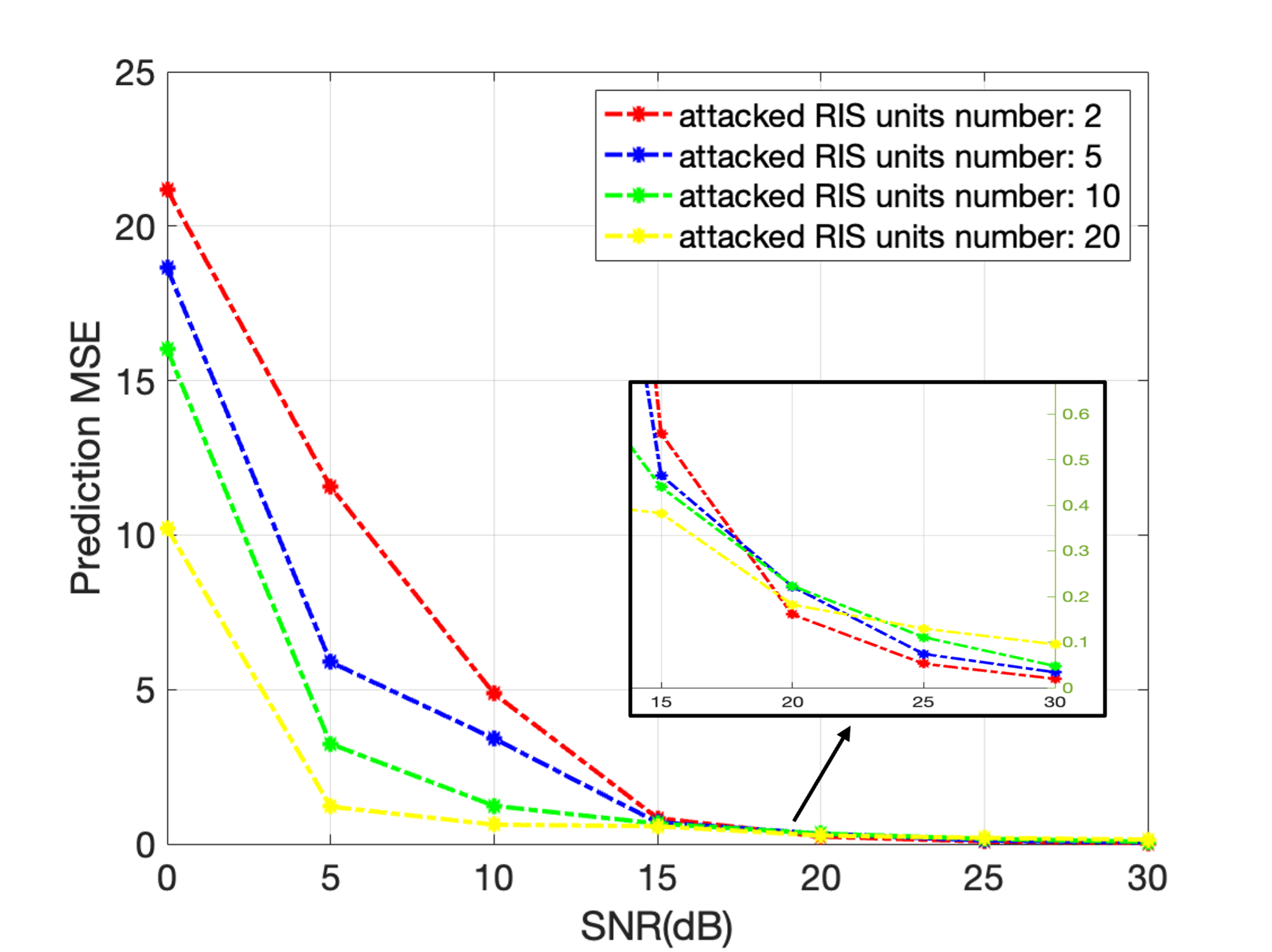
IV-B The expression of prediction MSE
Significantly lower mismatch probability is achieved when channel prediction is performed at the transmitter of the secure OFDM system. The performance improvement is more significant when the correlation coefficient between the forward and backward channels has a larger phase. Moreover, it can be observed from Fig. 3(b) that for all simulated scenarios, the interleaving pattern mismatch probability is insensitive to the correlation coefficients between the forward and backward channels when channel prediction-based reciprocity compensation is performed.
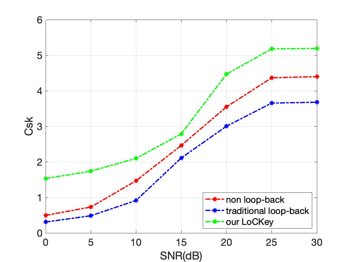
IV-C The improvement brought to key generation rate
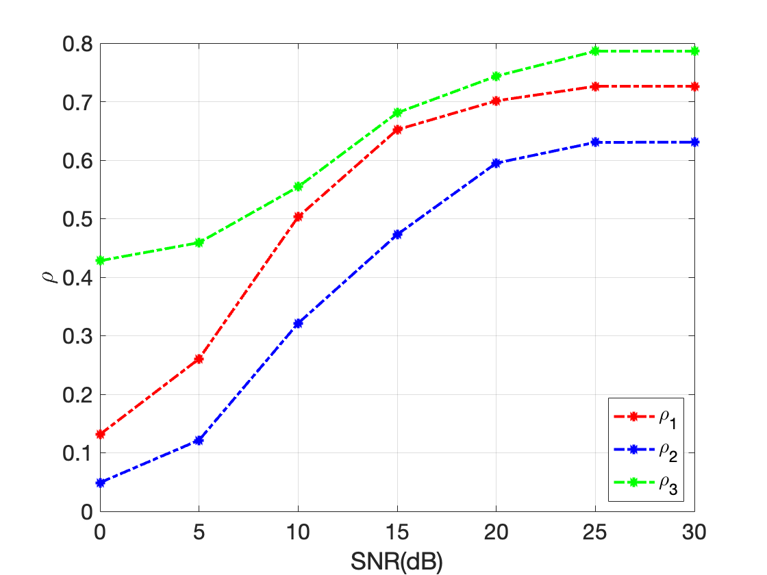
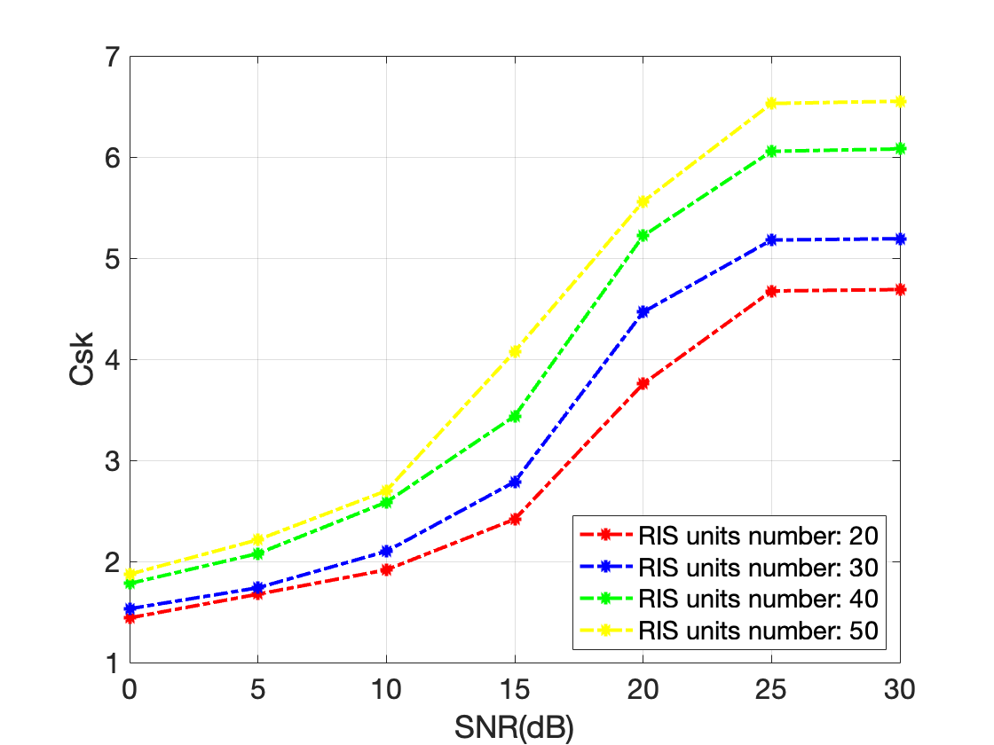
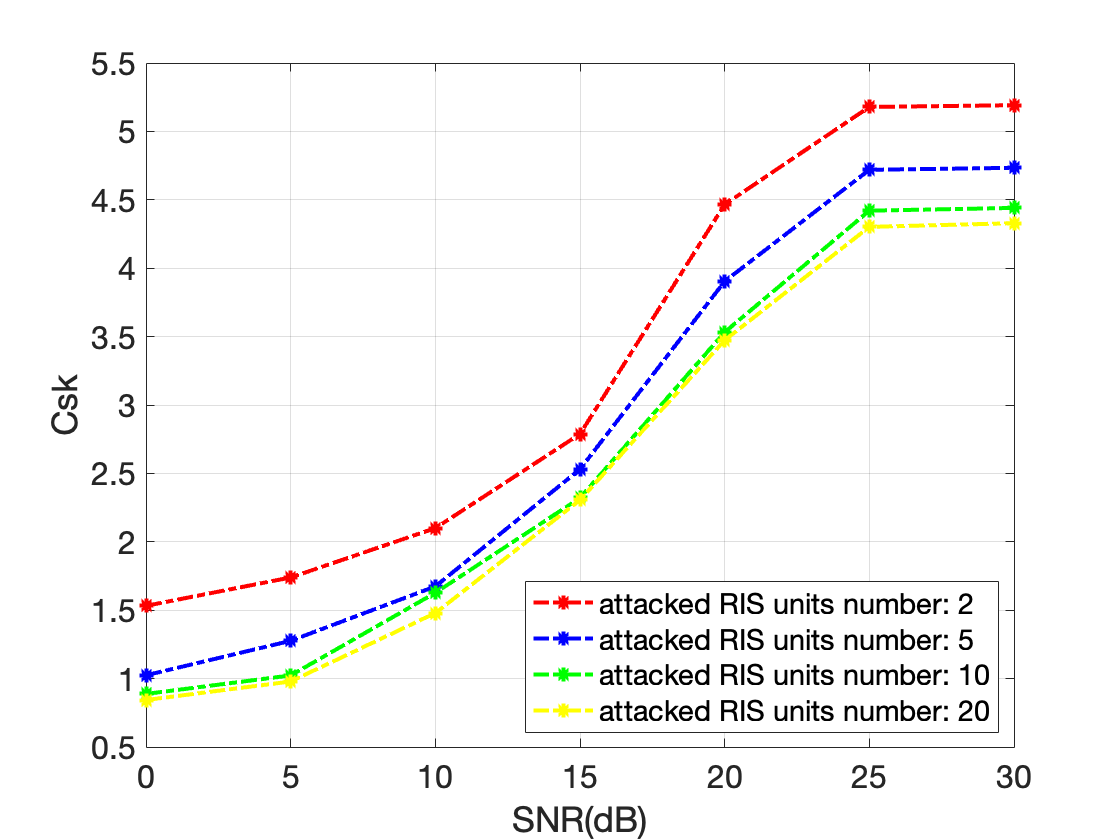
The key generation rate (KGR) is defined as the total generated key bit divided by the number of total used subcarriers. We conduct three experiments in this section to evaluate the system performance on KGR. First, we compare the KGR of our method with the traditional loop-back and non loop-back method when the number of RIS units is 30 and the number of interfered RIS units is 5 in Fig. 3(c). The simulation results show that the KGR of traditional loop-back is lower than that of non loop-back, which is consistent with the channel correlation curve. Our method is significantly superior to the two baselines, especially when the SNR is low (SNR10dB). In addition, we also compare the effects of our approach on KGR with different RIS element counts and different levels of interference against RIS. It can be easily inferred from Fig. 3(d) that our method plays a positive role under different numbers of RIS units, and the more RIS units there are, the greater the KGR growth rate will be. When the SNR reaches a higher level, the key generation speed tends to be stable, because the performance provided by RIS reaches the previous level. From Fig. 3(e), we learn that our method can counter interference attacks against RIS to different degrees, even if the interference rate reaches 2/3, it can ensure that KGR reaches 70% of the interference rate of 1/15.
IV-D The improvement brought to key consistency rate
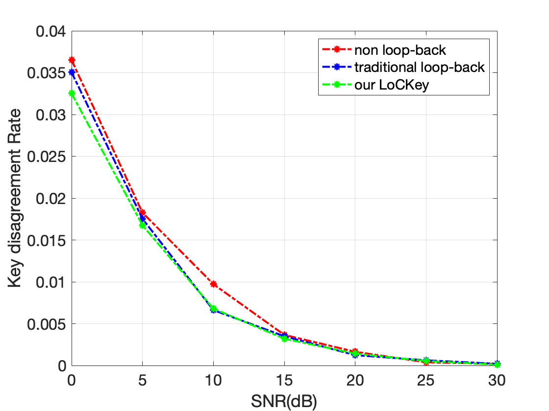
In addition to a significant increase of , our proposed channel compensation method can also significantly improve key consistency. Key Difference Rate (KDR) is defined as the total number of inconsistent key bits between two users divided by the total number of generated key bits. We use gray code for 2-bit quantization. Since there is only 1 bit of difference between adjacent code words in gray code, the inconsistency of the quantization sequence can be effectively limited. The mismatched key rate is calculated by dividing by the number of inconsistent bits on either side of the total key sequence. As can be seen from Figure 3(f), our method has a lower key inconsistency rate under any SNR condition, especially when the SNR is lower than that of the traditional loop-back method.
V Conclusion and Future Works
This paper proposes LoCKey, a novel approach that relies on a loop-back compensation scheme to improve channel reciprocity for physical layer key generation, aiming to effectively mitigate hardware interference and RIS-jamming attacks over open wireless channels. More specifically, the proposed LoCKey involves a novel MMSE compensation module with a signal loop-back strategy to strengthen the overall CSI reciprocity between endpoints. We provide a theoretical analysis to show how we achieve this goal. Experimental results show the superiority of our method. In the future, we will extend the proposed LoCKey to more scenarios, such as passive eavesdropping and multi-antennas, and will also develop a real-world testbed based on software-defined radio (SDR) and the OpenAirInterface (OAI) platform.
VI Acknowledgments
This work was supported by the National Key R&D Program of China (No. 2022YFB2902200).
References
- [1] Ji Xinsheng, Tao Xiaofeng, Huang Kaizhi, et al. Introduction to B5G Network security. Science in China: Information Science, 2021, 51:171 172, doi: 10.1360/ SSI-2020-0231.
- [2] W. Du, J. Deng, Y.S. Han, P.K. Varshney, J. Katz, and A. Khalili, ”A pairwise key predistribution scheme for wireless sensor networks,” ACM Trans. on Information and Systems Security, vol.8, pp.228-58, 2005.
- [3] Li G Y, Hu A Q, Shi L. Secret key extraction in wireless channel[J]. Journal of Cryptologic Research, 2014, 1(3): 211–224.
- [4] Kaizhi HUANG, et al. Development of Wireless Physical Layer Key Generation Technology and New Challenges[J]. Journal of Electronics & Information Technology, 2020, 42(10): 2330-2341.
- [5] Liu H, Wang Y, Yang J, et al. Fast and practical secret key extraction by exploiting channel response[C]. IEEE International Conference on Computer Communications—INFOCOM 2013. IEEE, 2013: 3048-3056.
- [6] G. Li, A. Hu, J. Zhang, L. Peng, C. Sun, and D. Cao, “High-agreement uncorrelated secret key generation based on principal component analysis preprocessing”, IEEE Transactions on Communications, vol. 66, no. 7, pp. 3022–3034, 2018.
- [7] Q. Wu and R. Zhang, “Intelligent reflecting surface enhanced wireless network via joint active and passive beamforming,” IEEE Transactions on Wireless Communications, vol. 18, no. 11, pp. 5394–5409, 2019.
- [8] T. Lu, L. Chen, J. Zhang, K. Cao and A. Hu, ”Reconfigurable Intelligent Surface Assisted Secret Key Generation in Quasi-Static Environments,” in IEEE Communications Letters, vol. 26, no. 2, pp. 244-248, Feb. 2022.
- [9] X. Lu, J. Lei, Y. Shi and W. Li, ”Intelligent Reflecting Surface Assisted Secret Key Generation,” in IEEE Signal Processing Letters, vol. 28, pp. 1036-1040, 2021.
- [10] L. Jin, X. Xu, S. Han, J. Liu, R. Meng and H. Chen, ”RIS-Assisted Physical Layer Key Generation and Transmit Power Minimization,” 2022 IEEE Wireless Communications and Networking Conference (WCNC), Austin, TX, USA, 2022, pp. 2065-2070.
- [11] Yang, S., Han, H., Liu, Y., Guo, W., Pang, Z. and Zhang, L. Reconfigurable Intelligent Surface-induced Randomness for mmWave Key Generation. IEEE ICC 2023, Rome, Italy.
- [12] Ayaz, Hina & Waqas, Muhammad & Abbas, Ghulam & Abbas, Ziaul & Bilal, Muhammad & Kwak, Kyung. (2022). Improved Rate of Secret Key Generation Using Passive Re-Configurable Intelligent Surfaces for Vehicular Networks. Sustainability. 15. 342.
- [13] M. Zafer, D. Agrawal, and M. Srivatsa, “Limitations of generating a secret key using wireless fading under active adversary,” IEEE ACM Trans. Netw., vol. 20, no. 5, pp. 1440–1451, Oct. 2012.
- [14] G. Li et al., ”Reconfigurable Intelligent Surface for Physical Layer Key Generation: Constructive or Destructive?,” in IEEE Wireless Communications, vol. 29, no. 4, pp. 146-153, August 2022.
- [15] Bin Lyu, Dinh Thai Hoang, Shimin Gong, Dusit Niyato, and Dong In Kim. Irs-based wireless jamming attacks: When jammers can attack without power. IEEE Wireless Communications Letters, 9(10):1663–1667, 2020.
- [16] L. Hu, G. Li, H. Luo, and A. Hu, “On the RIS manipulating attack and its countermeasures in physical-layer key generation”, IEEE Commun. Lett., vol. 26, no. 2, pp. 244–248, 2022.
- [17] S. Eberz, M. Strohmeier, M. Wilhelm, and I. Martinovic, “A practical man-in-the-middle attack on signal-based key generation protocols”, Proc. Eur. Symp. Res. Comput. Secur., 2012, pp. 235–252.
- [18] J. Zhang, A. Marshall, R. Woods, and T.Q. Duong, ”Efficient Key Generation by Exploiting Randomness From Channel Responses of Individual OFDM Subcarriers”, IEEE Trans. on Communications, vol. 64, no. 6, Jun. 2016.
- [19] Patwari N, Croft J, Jana S, et al. High-rate uncorrelated bit extraction for shared secret key generation from channel measurements[J]. IEEE Transactions on Mobile Computing, 2010, 9(1): 17–30.
- [20] Zhang Shengjun, Zhong Zhou, Jin Liang, et al. Method based on polarization code security key agreement [J]. Journal of electronics &information technology, 2019, 41 (6) : 7.
- [21] Rachmawati, D., Tarigan, J.T., & Ginting, A. (2018). A comparative study of Message Digest 5(MD5) and SHA256 algorithm. Journal of Physics: Conference Series, 978.