Advanced iontronic spiking modes with multiscale diffusive dynamics in a fluidic circuit
Abstract
Fluidic iontronics is emerging as a distinctive platform for implementing neuromorphic circuits, characterized by its reliance on the same aqueous medium and ionic signal carriers as the brain. Drawing upon recent theoretical advancements in both iontronic spiking circuits and in dynamic transport of aqueous electrolytes through conical ion channels, which form fluidic memristors, we expand the repertoire of proposed neuronal spiking dynamics in iontronic circuits. Through a modelled circuit containing channels that carry a bipolar surface charge, we extract phasic bursting, mixed-mode spiking, tonic bursting, and threshold variability, all with spike voltages and frequencies within the typical range for mammalian neurons. These features are possible due to the strong dependence of the typical conductance memory retention time on the channel length, enabling timescales varying from individual spikes to bursts of multiple spikes within a single circuit. These advanced forms of neuronal-like spiking support the exploration of aqueous iontronics as an interesting platform for neuromorphic circuits.
1 Introduction
In the pursuit of brain-inspired circuits the focus is often on the synaptic properties of neuromorphic devices, where synapses are considered as primary computational units in neuromorphic computing Schuman et al. (2022). Consequently, due to their analogous behaviour to synapses, memristors have significantly shaped and driven research in this domain, where the time- and history-dependent conductance of memristors offers a versatile platform for emulating features of synaptic plasticity Sangwan and Hersam (2020); Schuman et al. (2017); Zhu et al. (2020). However, synapses are not the only components in the brain which can be emulated with memristors. The biological ion channels responsible for generating action potentials also exhibit memristive behavior Sah et al. (2014). This is underscored by the seminal Hodgkin-Huxley (HH) model Hodgkin and Huxley (1952), which mathematically describes the axonal membrane potential by treating the membrane as an equivalent electric circuit in which the ion channels embedded in the axonal membrane are modelled as circuit components. The mathematical models for these ion channels were later recognised as descriptions of memristors Chua et al. (2012). Although both synapses and axonal ion channels are neuronal components that can be described and emulated by memristors, they are explicitly distinct biological structures which carry out different tasks. This biological nuance sometimes leads to confusion and inaccurate descriptions of memristive devices in the brain, such as incorrectly associating the HH model with descriptions of synapses Caravelli and Carbajal (2018). Nevertheless, the intriguing connection between memristors and the HH model has also sparked considerable interest Sah et al. (2014); Chua (2013) and neuronal signalling has inspired various circuits that capture various features of neuronal spiking Thakur et al. (2018); Yang et al. (2020).
Biological neurons feature a wealth of different spiking modes, which can be clearly categorised and used to judge the quality of neuron models Izhikevich (2004). Typically the most basic features to consider are tonic spiking, a regular train of voltage spikes with constant frequency, and phasic spiking, a single isolated voltage spike. In the case of phasic spiking, the neuron model should also obey the all-or-none law Zhu et al. (2020); Bean (2007), i.e. a voltage spike is either fully generated upon a sufficiently strong impulse, or the voltage fails to spike, with no intermediate transition in between. However, many more neuronal firing modes are recognised and this signalling behaviour of neurons has inspired various circuits that can emulate a wide array of different modes of neuronal spiking Thakur et al. (2018); Yang et al. (2020). Examples, that will also feature in the present study, include phasic bursting, mixed mode spiking, tonic bursting (otherwise known as chattering Gray and McCormick (1996)), and threshold variability Izhikevich (2004). In phasic bursting, a single burst of several spikes emerges upon applying a sustained stimulus, after which the system again settles to a steady state, despite the constant and sustained current stimulus. Mixed mode spiking consists of an initial burst of spikes upon a sustained stimulus, followed by tonic spiking. In tonic bursting, short periods of spiking, i.e. bursts, are interchanged by short periods of no spiking at all. Lastly, threshold variability indicates that the threshold for a neuron to spike can depend on the prior activity of the neuron.
The vast majority of neuromorphic devices, including the aforementioned spiking circuits Thakur et al. (2018); Yang et al. (2020), consist (at least partially) of solid-state components Sangwan and Hersam (2020); Schuman et al. (2017), which results in fundamental differences with biological neurons. For instance, while solid-state devices typically rely on a single information carrier, such as electrons or holes, driven only by electric forces, neurons employ the transport of various ions and molecules in parallel, while combining electrical en chemical regulation, both for signalling Micu et al. (2017) and for synaptic transmission Pereda and Purpura (2014); Xia and Storm (2005); Lüscher and Malenka (2012). Additionally, the fast dynamics of solid state components can be a disadvantage when temporal inputs are natural or biological signals as the typical timescales of those inputs can be significantly slower than those of solid-state devices, therefore requiring complicated virtual clocks for synchronisation Covi et al. (2021); Chicca and Indiveri (2020). Recent work tries to address and overcome these limitations through electrochemical coupling of solid-state components to ionic systems, both in the context of synaptic devices Wang et al. (2022); Van De Burgt et al. (2018) and for spiking circuits Harikesh et al. (2022, 2023); Luo et al. (2023). However, a newly emerging direction proposes to omit solid-state components altogether, and hence the need for any chemical or ionic coupling, by implementing neuromorphic features in an aqueous electrolyte medium Noy and Darling (2023); Noy et al. (2023); Robin et al. (2021, 2023); Xiong et al. (2023); Emmerich et al. (2023); Han et al. (2023); Xie et al. (2022). These (fluidic) iontronic devices have recently garnered significant interest, offering the promise of multiple information carriers, chemical regulation, and bio-integrability Han et al. (2022), although sacrificing on the high speeds obtainable by solid state devices. Unlike traditional solid-state neuromorphic circuits, fluidic iontronic circuits leverage the dynamic interplay of ions within an aqueous electrolyte, mirroring the conductive and fluidic characteristics inherent in biological neuronal environments. This departure from solid-state components introduces a novel dimension to neuromorphic computing, offering the potential for closer emulation of the brain’s aqueous dynamics. Recent advances include chemical regulation Robin et al. (2023); Xiong et al. (2023) and initial demonstrations of iontronic neuromorphic computing Kamsma et al. (2023b). However, the development of neuromorphic iontronic devices is still in its infancy, requiring further theoretical explorations and experimental investigations to establish their capabilities in emulating complex neuronal functionalities Han et al. (2022); Xie et al. (2022); Noy et al. (2023).
In the recent rise of interest in iontronic neuromorphics, spiking circuits also received some attention in the form of theoretical studies, where HH-inspired iontronic circuits are modelled and shown to exhibit features of neuronal spiking Robin et al. (2021); Kamsma et al. (2023a). These proposals feature a circuit composed of an aqueous electrolyte medium, akin to the neuronal medium that the HH model describes, and rely on fluidic iontronic memristors to induce neuronal spiking. Initially, tonic spiking was shown to emerge from a circuit containing angstrom-scale slits Robin et al. (2021), shortly after which an alternative iontronic circuit exploiting conical ion channels was proposed that exhibits both the characteristic all-or-none phasic spiking and tonic spiking Kamsma et al. (2023a). Thus, the two modes that are typically considered first Izhikevich (2004); Yang et al. (2020) have been theoretically predicted to also emerge from fluidic iontronic circuits. However, no proposals yet exist to also include other spiking modes.
In this work we expand upon the previously reported features of neuronal spiking in fluidic iontronics Robin et al. (2021); Kamsma et al. (2023a). By building upon a previously reported iontronic circuit Kamsma et al. (2023a) and a physical description of the dynamical conductance of conical channels with a bipolar surface charge Kamsma et al. (2023c), i.e. positive at the base and negative at the tip, we can unlock various new forms of spiking dynamics. Due to the strong dependence of the typical conductance memory retention time on the channel length, we can implement timescales varying from individual spikes to bursts of multiple spikes within a single circuit, thereby enabling new spiking modes. Specifically these spiking modes are the aforementioned phasic bursting, mixed mode spiking, tonic bursting, and threshold variability Izhikevich (2004).
2 Iontronic circuit and bipolar channels
Conical fluidic ion channels act as iontronic volatile memristors Wang et al. (2012) and are being investigated as possible candidates for synaptic devices Ramirez et al. (2023) and spiking circuits Kamsma et al. (2023a, c). Using theoretical models that quantitatively explain the memristive behaviour of conical channels, we showed that HH-inspired fluidic circuits containing three conical channels and a capacitor exhibit tonic and phasic spiking Kamsma et al. (2023a, c). This modelled circuit was originally composed of conical ion channels with a homogeneous unipolar (UP) surface charge Kamsma et al. (2023a) and was later modified by replacing the UP channels with conical channels carrying a bipolar (BP) inhomogeneous surface charge Kamsma et al. (2023c), positive at the base and negative at the tip. This modification from a UP to a BP surface charge led, for an individual conical channel, to a much more pronounced current-voltage hysteresis loop upon applying an AC voltage, i.e. a stronger conductance memory effect. Here we consider a circuit containing several of these conical BP channels, with different lengths . An important feature of these BP channel memristors is that their typical conductance memory timescale is dictated by the channel lengths according to
| (1) |
with the diffusion coefficient of the ions Kamsma et al. (2023c), which we assume to be identical for all ionic species for convenience. As we will discuss later on, the combination of channels of various lengths in a single circuit gives rise to dynamics on the timescale of individual spikes and of bursts of spikes in the same circuit.
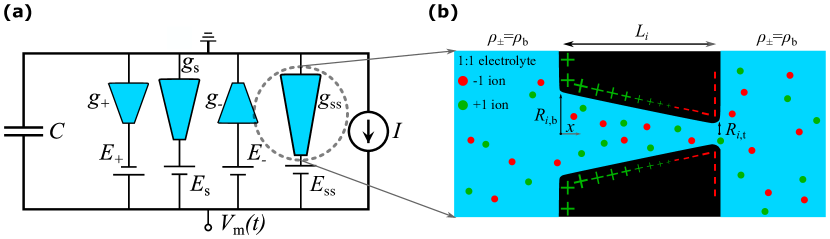
To unlock additional features of neuronal firing, beyond tonic and phasic spiking, we introduce the circuit schematically depicted in Fig. 1(a), containing a capacitor with capacitance pF, a typical capacitance for a mammalian neuronal membrane with an area of order Gentet et al. (2000); Major et al. (1994), i.e. of the same order as the cross-sectional area of a channel. This capacitor is connected in parallel with four BP conical channels with conductances , , , and , and four batteries each in series with the conical channels. The channels are taken to be of varying lengths , , and . Through Eq. (1) this translates to timescales ms for the two fast channels, for the slow channel, and for the super slow channel. The batteries, with which the BP conical channels are connected in series, have potentials for the two fast channels, and for the slow and super slow channel. These batteries, which mimic the Nernst potential caused by ionic concentration differences inside and outside the neuron in the original HH circuit Hodgkin and Huxley (1952), are considered to be actual batteries in the microfluidic circuit of interest here, but their potentials are comparable to their biological Nernst potential counterparts L. Squire, D. Berg, F. Bloom, S. du Lac, A. Ghosh, N. Spitzer (2008).
In Fig. 1(b) we show a schematic depiction of a BP channel, implemented in the circuit in Fig. 1(a), with base- and tip radii and , respectively, and thus with radius for positions in the channel. The channel of length connects two 1:1 aqueous electrolyte reservoirs with the viscosity and the electric permittivity of water. The cationic and anionic bulk concentrations are given by mM, comparable to the extracellular potassium concentration in biological neurons L. Squire, D. Berg, F. Bloom, S. du Lac, A. Ghosh, N. Spitzer (2008), which gives rise to a Debye length . The channels carry a surface charge that linearly decreases from at the broad base to at the narrow tip, thereby changing by over the channel length and forming a bipolar surface charge profile. On the basis of the Gouy-Chapman relation, these charge densities correspond to zeta potentials that vary between and . For the short fast channels and the slow channel we fix nm and nm, while the super slow channel is narrower with nm and nm. Thus, in all cases the channel radii are substantially larger than the Debye length, such that overlap of electric double layers is not prominent.
To fully resolve the dynamics of the circuit depicted in Fig. 1(a), we have to know how the conductances of the BP channels evolve. For this we use an analytical model that quantitatively describes the steady-state and dynamical conductance properties of BP channels Kamsma et al. (2023c). Each of the four BP channels exhibits voltage-dependent salt concentration polarisation in steady-state described by
| (2) |
with the Péclet number at the narrow end and the volume flow through the channel. The system is considered to be at a temperature of K and the effective surface potential mV is taken to be the same as in Ref. Kamsma et al. (2023c) as we consider the same surface charge distributions here. The accumulation or depletion of salt affects the conductance of the channel according to
| (3) |
with the homogeneous channel conductance. In the numerical evaluation of Eq. (3) we replace by to avoid nonphysical negative concentrations that can emerge due to the strong voltage-dependent salt depletion of BP channels Kamsma et al. (2023c). This approach does induce a sharper drop in conductance, compared to full finite-element simulations, when concentrations start to approach the imposed minimum of , discussed in more detail in the Supplemental Material. This artefact complicates the circuit equations we introduce below. To help smooth over this sharper drop we employ a third-order interpolation to evaluate Eq. (3) between voltages spaced at intervals of 0.025 V, ranging from -0.3125 to 0.3125 V. A more sophisticated theoretical model of individual channels in the future should obviate the need for such an ad hoc approach, but for now this effective method suffices.
Since it takes a typical time as per Eq. (1) for salt to accumulate or deplete, the channel exhibits a (volatile) memory conductance with typical memory retention time . The resulting dynamic conductance was found to be well described by
| (4) |
where is the potential difference between base and tip of the channel, is the voltage-dependent steady-state conductance of the channel as per Eq. (3), and is the typical conductance memory retention timescale of the channel given by Eq. (1) Kamsma et al. (2023c).
With differential equations for each of the dynamic conductances , we only need one additional equation to close the set that describes the time-evolution of the “membrane” potential , here the potential over the capacitor. This additional equation is provided by Kirchhoff’s law
| (5) |
where and the conductances each evolve according to Eq. (4) with their corresponding and . The voltage arguments over the channels are given by , , , and , with the different signs of the potentials corresponding to the different orientations of the channels as depicted in Fig. 1(a). Using the initial conditions and , with as defined below Eq. (3), we numerically solve the closed set of Eqs. (1), (4) and (5) for various current stimuli .
3 Advanced iontronic spiking modes
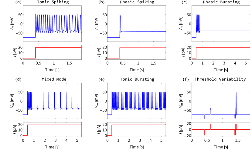
Upon numerically evaluating the membrane potential that emerges from the proposed fluidic iontronic circuit introduced in Sec. 2 for various stimuli, we reveal the remarkable diversity of typical neuronal firing modes Izhikevich (2004) shown in Fig. 2, which we will discuss individually below. We stress that all spiking modes discussed below originate from one and the same iontronic circuit, with the stimulus current the only difference between the spiking modes. Additionally, we note that all spikes exhibit voltage amplitudes and spiking frequencies that are typical for mammalian neurons Bean (2007).
3.1 Tonic Spiking and Phasic Spiking
The earlier reported foundational tonic Robin et al. (2021); Kamsma et al. (2023a) and phasic spiking Kamsma et al. (2023a) also emerge from the circuit we consider here. Tonic spiking, characterized by a regular train of voltage spikes as shown in Fig. 2(a), and phasic spiking, featuring a single isolated voltage spike as shown in Fig. 2(b), appear for the present system parameters under sustained current stimuli of 18.90 pA and 19.05 pA, respectively. The sustained current of Fig. 2(b) does give rise, after the single voltage pulse, to a steady voltage that differs from the initial voltage. An all-or-none spike can also appear upon a pulse stimulus, after which the voltage settles back to its initial steady-state Kamsma et al. (2023c).
The dynamics here are governed by the typical RC-like time of the circuit that determines the time it takes for the (de)polarisation of , while the timescale dictates the typical width of a spike; the short channels respond on such fast timescales that their dynamics can actually be assumed to be instantaneous Kamsma et al. (2023a, 2024). Although the timescale does not play a role in these spiking modes as these also appear without the super slow channel Kamsma et al. (2023c), a small influence of the super slow channel is still visible in the case of tonic spiking. The spiking frequency initially is slightly higher immediately after the stimulus is applied and then gradually settles into a lower frequency over a time . This actually corresponds to the spiking mode of spike frequency adaptation Izhikevich (2004), but since this effect is so minor in our results, we choose not to explicitly distinguish it as an additional emerging spiking mode.
3.2 Phasic Bursting
Imposing a sustained current stimulus to the circuit of 19.01 pA elicits phasic bursting, a spiking mode where a burst of spikes occurs, followed by a return to a (new) steady state, despite the sustained stimulus. This mode is made possible by the super slow channel. The initial burst has a duration of the typical timescale of the super slow channel, after which this channel has had sufficient time to increase its conductance to return the system to a steady state.
3.3 Mixed Mode
Under a sustained stimulus of 19.02 pA we find mixed mode spiking, i.e. the iontronic circuit transitions from an initial high-frequency burst of spikes with a duration of , into a lower frequency tonic spiking, with the individual spikes now separated by , as shown in Fig. 2(d). In this case the initial burst is a transient, of typical time , as the system settles into the periodic solution of the tonic spiking.
3.4 Tonic Bursting
Tonic bursting entails short bursts of spiking interspersed with periods of quiescence. When imposing a sustained stimulus of 19.04 pA we find that the circuit exhibits a periodic behaviour of high frequency burst as shown in Fig. 2(e). The durations of the bursts and periods of quiescence are dictated by the slow dynamics of longest channel, as the super slow channel periodically increases and decreases in conductance, visible by the fact that each burst has a duration of order ms.
3.5 Threshold Variability
Our findings also unveil threshold variability, wherein the firing threshold of the neuron is influenced by prior activity. As shown in Fig. 2(f), when imposing a negative and positive stimulus pulse of magnitude pA of duration 0.02 s, separated by 0.18 s (between the end of the first pulse and the beginning of the second) no spike occurs. However, when we impose precisely the same pulses but now separated by 0.01 s we find that a full spike occurs. Thus in the first set of pulses, the threshold for spiking was not reached, but in the second instance it was reached with exactly the same pulses, showing that the prior activity of the circuit can influence the threshold for spiking. This is a result of the slow channel with timescale decreasing in conductance as a result of the negative pulse, while the super slow channel actually plays no role in this spiking mode as it is also observed without the super slow channel. If the interval is much larger than ms, as it is for the first set of pulses, then the slow channel reverts to its steady-state before the second pulse. However, if the interval between the stimuli is of the order of ms (or smaller), as is the case in the second set of pulses where the interval is 10 ms, then the slow channel still has a lowered conductance when the second pulse arrives, making the system more susceptible to stimuli and thereby lowering the firing threshold.
4 Discussion and conclusion
Previously reported fluidic iontronic circuits have demonstrated tonic spiking Robin et al. (2021); Kamsma et al. (2023a) and phasic spiking Kamsma et al. (2023a). In this study, we extend the repertoire of emergent spiking modes by introducing a new HH-like fluidic iontronic circuit, consisting of a capacitor and four iontronic memristors, that exhibits phasic bursting, mixed-mode spiking, tonic bursting, and threshold variability Izhikevich (2004), as well as the earlier reported tonic and phasic spiking Robin et al. (2021); Kamsma et al. (2023a). The spikes in our proposed modes exhibit voltages and frequencies that align with those observed in mammalian neurons Bean (2007). Moreover, the capacitance, battery potentials and salt concentration in the circuit are comparable to their biological counterparts L. Squire, D. Berg, F. Bloom, S. du Lac, A. Ghosh, N. Spitzer (2008). Our theoretical framework builds upon a previously proposed iontronic circuit that exhibits tonic and phasic spiking Kamsma et al. (2023a) and a physical model for conical ion channels with a bipolar (rather than unipolar) surface charge Kamsma et al. (2023c). These channels are memristive Kamsma et al. (2023c) and their typical conductance memory retention time is dependent on the channel length. By varying the lengths of the four channels we can incorporate timescales on the order of a single spike and of entire bursts in a single circuit, allowing for the individual spiking and bursting processes that emerge from one and the same circuit.
While our theoretical framework in principle is fully physical, a limitation is the parameter sensitivity of the system, at least for the system parameters we considered. The stimuli strengths that induce different spiking modes are only separated by pA on the scale of about 20 pA. Additionally, small changes in other circuit parameters such as the battery potential can also strongly affect the emergent behaviour of the circuit. The implementation of the batteries in series with channels was remarked to likely be an experimental challenge in and of itself Abayzeed et al. (2023). While the sensitivity of the system can offer some advantages in terms of how responsive the system is to inputs, it could also complicate the experimental feasability of the circuit. This sensitivity could possibly be reduced in the future by implementing memristors with a wider range of available conductances, as the bipolar channels we currently model only offer a current rectification of around Kamsma et al. (2023c). Channels with higher current rectification ratios, and therefore larger ranges of attainable conductances, do exist Choi et al. (2016); Kim et al. (2022) and some of these are already shown to be memristive and can even be described by similar theoretical models as we use here Kamsma et al. (2023b). This suggestion for future improvements is supported by the fact that the results presented here are already an expansion on results we derived earlier for simpler unipolar conical channels carrying a homogeneous surface charge. Tonic bursting also emerges from a similar circuit with unipolar channels, but with circuit parameters (i.e. higher battery potentials, lower salt concentration, lower capacitance) and spiking voltages that are further removed from their biological analogs. The specific parameters for the unipolar channel circuit are laid out in the Supplemental Material. The emergence of tonic bursting in a different circuit with different fluidic memristors than the bipolar channels we use here shows that the bursting spiking modes we present are not inherently dependent on a single specific type of memristor. Therefore, possible further improvements can be achieved by considering fluidic iontronic memristors with an even wider range of attainable conductances. However, this is an issue of individual device physics and here we mostly focused on the overall circuit architecture and the spiking modes it enables.
In summary, we have considerably expanded the range of spiking modes proposed to emerge from iontronic fluidic circuits based on bipolar conical channels, entailing phasic bursting, mixed-mode spiking, tonic bursting, and threshold variability. The alignment of the spikes in our results with typical mammalian neuronal voltages and frequencies, combined with various circuit parameters that are comparable to their biological counterparts, further supports the potential that fluidic iontronics carry for neuromorphic spiking circuits. Furthermore, since these biologically realistic spikes emerge from a circuit that is based upon the same aqueous electrolyte medium as in neurons, a unique perspective is the future possible integration with biological systems. However, the present system is rather sensitive to stimulus strengths and other circuit parameters, a limitation that may be mitigated by implementing memristors with a broader range of available conductances. Nevertheless, we showed that the multiscale diffusive timescales of fluidic iontronic memristors of different lengths facilitate a relatively simple circuit that exhibits various advanced modes of neuronal spiking. Consequently, this work contributes to the ongoing exploration of fluidic iontronics as a promising platform for neuromorphic circuits, providing theoretical insights and proposed applications, thereby paving the way for future advancements in this burgeoning field.
Acknowledgements.
This work is part of the D-ITP consortium, a program of the Netherlands Organisation for Scientific Research (NWO) that is funded by the Dutch Ministry of Education, Culture and Science (OCW).References
- Schuman et al. (2022) C. D. Schuman, S. R. Kulkarni, M. Parsa, J. P. Mitchell, P. Date, and B. Kay, “Opportunities for neuromorphic computing algorithms and applications,” Nature Computational Science 2, 10–19 (2022).
- Sangwan and Hersam (2020) V. K. Sangwan and M. C. Hersam, “Neuromorphic nanoelectronic materials,” Nature Nanotechnology 15, 517–528 (2020).
- Schuman et al. (2017) C. D. Schuman, T. E. Potok, R. M. Patton, J. D. Birdwell, M. E. Dean, G. S. Rose, and J. S. Plank, “A Survey of Neuromorphic Computing and Neural Networks in Hardware,” arXiv (2017).
- Zhu et al. (2020) J. Zhu, T. Zhang, Y. Yang, and R. Huang, “A comprehensive review on emerging artificial neuromorphic devices,” Applied Physics Reviews 7, 011312 (2020).
- Sah et al. (2014) M. P. Sah, H. Kim, and L. O. Chua, “Brains are made of memristors,” IEEE Circuits and Systems Magazine 14, 12–36 (2014).
- Hodgkin and Huxley (1952) A. L. Hodgkin and A. F. Huxley, “A quantitative description of membrane current and its application to conduction and excitation in nerve,” The Journal of Physiology 117, 500 (1952).
- Chua et al. (2012) L. Chua, V. Sbitnev, and H. Kim, “Hodgkin-Huxley axon is made of memristors,” https://doi-org.proxy.library.uu.nl/10.1142/S021812741230011X 22, 1230011 (2012).
- Caravelli and Carbajal (2018) F. Caravelli and J. P. Carbajal, “Memristors for the Curious Outsiders,” Technologies 2018, Vol. 6, Page 118 6, 118 (2018).
- Chua (2013) L. Chua, “Memristor, Hodgkin-Huxley, and edge of chaos,” Nanotechnology 24 (2013), 10.1088/0957-4484/24/38/383001.
- Thakur et al. (2018) C. S. Thakur, J. L. Molin, G. Cauwenberghs, G. Indiveri, K. Kumar, N. Qiao, J. Schemmel, R. Wang, E. Chicca, J. Olson Hasler, J. S. Seo, S. Yu, Y. Cao, A. van Schaik, and R. Etienne-Cummings, “Large-Scale Neuromorphic Spiking Array Processors: A Quest to Mimic the Brain,” Frontiers in Neuroscience 12, 353526 (2018).
- Yang et al. (2020) J.-Q. Yang, R. Wang, Y. Ren, J.-Y. Mao, Z.-P. Wang, Y. Zhou, S.-T. Han, J.-q. Yang, R. Wang, S.-t. Han, Y. Ren, J.-y. Mao, Z.-p. Wang, and Y. Zhou, “Neuromorphic Engineering: From Biological to Spike-Based Hardware Nervous Systems,” Advanced Materials 32, 2003610 (2020).
- Izhikevich (2004) E. M. Izhikevich, “Which model to use for cortical spiking neurons?” IEEE Transactions on Neural Networks 15, 1063–1070 (2004).
- Bean (2007) B. P. Bean, “The action potential in mammalian central neurons,” Nature Reviews Neuroscience 2007 8:6 8, 451–465 (2007).
- Gray and McCormick (1996) C. M. Gray and D. A. McCormick, “Chattering Cells: Superficial Pyramidal Neurons Contributing to the Generation of Synchronous Oscillations in the Visual Cortex,” Science 274, 109–113 (1996).
- Kamsma et al. (2023a) T. Kamsma, W. Boon, T. Ter Rele, C. Spitoni, and R. Van Roij, “Iontronic Neuromorphic Signaling with Conical Microfluidic Memristors,” Physical Review Letters 130 (2023a), 10.1103/PhysRevLett.130.268401.
- Micu et al. (2017) I. Micu, J. R. Plemel, A. V. Caprariello, K. A. Nave, and P. K. Stys, “Axo-myelinic neurotransmission: a novel mode of cell signalling in the central nervous system,” Nature Reviews Neuroscience 2017 19:1 19, 49–58 (2017).
- Pereda and Purpura (2014) A. E. Pereda and D. P. Purpura, “Electrical synapses and their functional interactions with chemical synapses,” Nature Reviews Neuroscience 2014 15:4 15, 250–263 (2014).
- Xia and Storm (2005) Z. Xia and D. R. Storm, “The role of calmodulin as a signal integrator for synaptic plasticity,” Nature Reviews Neuroscience 6, 267–276 (2005).
- Lüscher and Malenka (2012) C. Lüscher and R. C. Malenka, “NMDA Receptor-Dependent Long-Term Potentiation and Long-Term Depression (LTP/LTD),” Cold Spring Harbor Perspectives in Biology 4, 1–15 (2012).
- Covi et al. (2021) E. Covi, E. Donati, X. Liang, D. Kappel, H. Heidari, M. Payvand, and W. Wang, “Adaptive Extreme Edge Computing for Wearable Devices,” Frontiers in Neuroscience 15, 611300 (2021).
- Chicca and Indiveri (2020) E. Chicca and G. Indiveri, “A recipe for creating ideal hybrid memristive-CMOS neuromorphic processing systems,” Applied Physics Letters 116, 120501 (2020).
- Wang et al. (2022) Y. Wang, Q. Zhang, H. P. Astier, C. Nickle, S. Soni, F. A. Alami, A. Borrini, Z. Zhang, C. Honnigfort, B. Braunschweig, A. Leoncini, D. C. Qi, Y. Han, E. del Barco, D. Thompson, and C. A. Nijhuis, “Dynamic molecular switches with hysteretic negative differential conductance emulating synaptic behaviour,” Nature Materials 2022 21:12 21, 1403–1411 (2022).
- Van De Burgt et al. (2018) Y. Van De Burgt, A. Melianas, S. T. Keene, G. Malliaras, and A. Salleo, “Organic electronics for neuromorphic computing,” Nature Electronics 1, 386–397 (2018).
- Harikesh et al. (2022) P. C. Harikesh, C. Y. Yang, D. Tu, J. Y. Gerasimov, A. M. Dar, A. Armada-Moreira, M. Massetti, R. Kroon, D. Bliman, R. Olsson, E. Stavrinidou, M. Berggren, and S. Fabiano, “Organic electrochemical neurons and synapses with ion mediated spiking,” Nature Communications 2022 13:1 13, 1–9 (2022).
- Harikesh et al. (2023) P. C. Harikesh, C. Y. Yang, H. Y. Wu, S. Zhang, M. J. Donahue, A. S. Caravaca, J. D. Huang, P. S. Olofsson, M. Berggren, D. Tu, and S. Fabiano, “Ion-tunable antiambipolarity in mixed ion-electron conducting polymers enables biorealistic organic electrochemical neurons,” Nature Materials 22, 242–248 (2023).
- Luo et al. (2023) S. Luo, L. Shao, D. Ji, Y. Chen, X. Wang, Y. Wu, D. Kong, M. Guo, D. Wei, Y. Zhao, Y. Liu, and D. Wei, “Highly Bionic Neurotransmitter-Communicated Neurons Following Integrate-and-Fire Dynamics,” Nano Letters 23, 4974–4982 (2023).
- Noy and Darling (2023) A. Noy and S. B. Darling, “Nanofluidic computing makes a splash,” Science 379, 143–144 (2023).
- Noy et al. (2023) A. Noy, Z. Li, and S. B. Darling, “Fluid learning: Mimicking brain computing with neuromorphic nanofluidic devices,” Nano Today 53, 102043 (2023).
- Robin et al. (2021) P. Robin, N. Kavokine, and L. Bocquet, “Modeling of emergent memory and voltage spiking in ionic transport through angstrom-scale slits,” Science 373, 687–691 (2021).
- Robin et al. (2023) P. Robin, T. Emmerich, A. Ismail, A. Niguès, Y. You, G.-h. Nam, A. Keerthi, A. Siria, A. K. Geim, B. Radha, and L. Bocquet, “Long-term memory and synapse-like dynamics in two-dimensional nanofluidic channels,” Science 379, 161–167 (2023).
- Xiong et al. (2023) T. Xiong, C. Li, X. He, B. Xie, J. Zong, Y. Jiang, W. Ma, F. Wu, J. Fei, P. Yu, and L. Mao, “Neuromorphic functions with a polyelectrolyte-confined fluidic memristor,” Science 379, 156–161 (2023).
- Emmerich et al. (2023) T. Emmerich, Y. Teng, N. Ronceray, E. Lopriore, R. Chiesa, A. Chernev, V. Artemov, M. Di Ventra, A. Kis, and A. Radenovic, “Ionic logic with highly asymmetric nanofluidic memristive switches,” arXiv preprint (2023).
- Han et al. (2023) S. H. Han, S. I. Kim, M. A. Oh, and T. D. Chung, “Iontronic analog of synaptic plasticity: Hydrogel-based ionic diode with chemical precipitation and dissolution,” Proceedings of the National Academy of Sciences of the United States of America 120, e2211442120 (2023).
- Xie et al. (2022) B. Xie, T. Xiong, W. Li, T. Gao, J. Zong, Y. Liu, and P. Yu, “Perspective on Nanofluidic Memristors: From Mechanism to Application,” Chemistry - An Asian Journal 17, e202200682 (2022).
- Han et al. (2022) S. H. Han, M.-A. Oh, and T. D. Chung, “Iontronics: Aqueous ion-based engineering for bioinspired functionalities and applications,” Chemical Physics Reviews 3, 031302 (2022).
- Kamsma et al. (2023b) T. M. Kamsma, J. Kim, K. Kim, W. Boon, C. Spitoni, J. Park, and R. van Roij, “Brain-inspired computing with fluidic iontronic nanochannels,” (2023b).
- Kamsma et al. (2023c) T. Kamsma, W. Boon, C. Spitoni, and R. van Roij, “Unveiling the capabilities of bipolar conical channels in neuromorphic iontronics,” Faraday Discussions 246 (2023c), 10.1039/d3fd00022b.
- Wang et al. (2012) D. Wang, M. Kvetny, J. Liu, W. Brown, Y. Li, and G. Wang, “Transmembrane potential across single conical nanopores and resulting memristive and memcapacitive ion transport,” Journal of the American Chemical Society 134, 3651–3654 (2012).
- Ramirez et al. (2023) P. Ramirez, V. Gómez, J. Cervera, S. Mafe, and J. Bisquert, “Synaptical Tunability of Multipore Nanofluidic Memristors,” The Journal of Physical Chemistry Letters 14, 10930–10934 (2023).
- Gentet et al. (2000) L. J. Gentet, G. J. Stuart, and J. D. Clements, “Direct Measurement of Specific Membrane Capacitance in Neurons,” Biophysical Journal 79, 314–320 (2000).
- Major et al. (1994) G. Major, A. U. Larkman, P. Jonas, B. Sakmann, and J. J. B. Jack, “Detailed passive cable models of whole-cell recorded CA3 pyramidal neurons in rat hippocampal slices,” Journal of Neuroscience 14, 4613–4638 (1994).
- L. Squire, D. Berg, F. Bloom, S. du Lac, A. Ghosh, N. Spitzer (2008) L. Squire, D. Berg, F. Bloom, S. du Lac, A. Ghosh, N. Spitzer, Fundamental Neuroscience, 3rd ed. (Academic Press, 2008) Chap. 6.
- Kamsma et al. (2024) T. M. Kamsma, R. van Roij, and C. Spitoni, “A mathematical theory for first-order volatile memristors and their spiking circuits,” Manuscript in preparation (2024).
- Abayzeed et al. (2023) S. Abayzeed, T. Anwar, A. Barnaveli, M. Bazant, L. Bocquet, A. Donev, R. Dryfe, S. Faez, A. Janardanan, F. Jiménez-Ángeles, T. Kamsma, F. Kanoufi, A. Kornyshev, S. Lemay, Y. Levin, S. Marbach, J. Montes de Oca, P. Robin, Z. Siwy, D. Stein, R. van Roij, T. Vidaković-Koch, G. Yossifon, and Y. Zhang, “Iontronic coupling: general discussion,” Faraday Discussions (2023), 10.1039/d3fd90031b.
- Choi et al. (2016) E. Choi, C. Wang, G. T. Chang, and J. Park, “High Current Ionic Diode Using Homogeneously Charged Asymmetric Nanochannel Network Membrane,” Nano Letters 16, 2189–2197 (2016).
- Kim et al. (2022) J. Kim, J. Jeon, C. Wang, G. T. Chang, and J. Park, “Asymmetric Nanochannel Network-Based Bipolar Ionic Diode for Enhanced Heavy Metal Ion Detection,” ACS Nano (2022), 10.1021/acsnano.2c02016.