A Multi-scale Yarn Appearance Model with Fiber Details
Abstract.
Rendering realistic cloth has always been a challenge due to its intricate structure. Cloth is made up of fibers, plies, and yarns, and previous curved-based models, while detailed, were computationally expensive and inflexible for large cloth. To address this, we propose a simplified approach.
We introduce a geometric aggregation technique that reduces ray-tracing computation by using fewer curves, focusing only on yarn curves. Our model generates ply and fiber shapes implicitly, compensating for the lack of explicit geometry with a novel shadowing component. We also present a shading model that simplifies light interactions among fibers by categorizing them into four components, accurately capturing specular and scattered light in both forward and backward directions.
To render large cloth efficiently, we propose a multi-scale solution based on pixel coverage. Our yarn shading model outperforms previous methods, achieving rendering speeds 3-5 times faster with less memory in near-field views. Additionally, our multi-scale solution offers a 20% speed boost for distant cloth observation.
- BCSDF
- Bidirectional Curve Scattering Distribution Function
- BSDF
- Bidirectional Scattering Distribution Function
- BRDF
- Bidirectional Reflection Distribution Function
- BTF
- Bidirectional Texture Functions
- Probability Density Function
- DS
- dual scattering
1. Introduction
Fabrics are an integral part of our everyday lives, serving a wide range of purposes from clothing to functional textiles such as curtains, furniture, and table sheets. Accurately modeling the appearance of cloth in a physically faithful manner has extensive applications in various fields, including design, online retail, and entertainment. However, they present a challenge due to their complex geometry and optics, with a hierarchical structure consisting of yarns, plies, and individual fibers.
In the realm of computer graphics, researchers have explored predominantly two primary approaches for cloth rendering: surface-based and curve-based methods. Surface-based models represent cloth geometry using 2D sheets, often in the form of polygonal meshes (Adabala et al., 2003; Sadeghi et al., 2013; Irawan and Marschner, 2012; Zhu et al., 2022). While these models offer lightweight and editable representations suitable for macroscopic scale, they lack the fine-grained details required to convincingly render cloth in close-up views.
On the other hand, curve-based models focus on capturing intricate cloth details by representing the geometry at a microscale (Khungurn et al., 2015; Zhao et al., 2011). These models delve into the structure of individual fibers and utilize volumetric or fiber-based light scattering models to simulate light interactions. While these approaches can achieve highly realistic renderings with exceptional fidelity, they suffer from computational expense, making them slow and challenging to manipulate.
To address these limitations, Montazeri et al. (2020) introduced a novel approach that replaces the explicit representation of individual fibers with ply curves, implicitly incorporating fiber details. However, we desire an even more simplified model; we aim to represent the cloth solely with yarn curves. Building upon this ply-based approach, we pose the question: Can we completely conceal the hierarchical structure as well as the light transport within the yarns, treating the yarn as a whole aggregated model that embeds all sub-yarn geometries and light transport? This question presents a notably higher level of difficulty compared to the ply-based model. It requires simplifying the geometry when a ray interacts with a yarn, aggregating light interactions among plies as well as fibers, and ensuring both efficiency and accuracy without introducing obvious trade-offs.
In this paper, we make the following contributions:
Accurate geometric representation with fiber details: We propose using yarn curves as input geometry and dynamically computing ply and fiber details during rendering (§3). This approach allows us to achieve significant efficiency improvements while maintaining the same level of fidelity, surpassing previous models such as the ply-based model (Montazeri et al., 2020) and fiber-based ones (Khungurn et al., 2015).
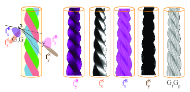
An aggregated yarn-based appearance representation: We introduce a Bidirectional Yarn Scattering Distribution Function (BYSDF), a shading model that computes the appearance of the yarn as a whole using four components, following similar notations as Montazeri et al. (2020) but now at the yarn-level representation (§4.1). These components include reflected and transmitted specular components that capture highlights bouncing off the surface or transmitted through the cloth without much scattering, as well as reflected and transmitted body components that approximate scattered light within the yarn medium. Additionally, we propose a novel consideration for self-shadowing to compensate for the lack of sub-yarn geometry (§5).
Multi-scale solution: Our model begins with a near-field solution to accurately depict the appearance of yarns and seamlessly transitions between near-field and far-field rendering using an efficient integration technique based on pixel coverage (§4.2). Inspired by fur and hair models (Chiang et al., 2015; Yan et al., 2017a), our approach addresses the issue of resolving individual highlights within yarns when viewed from a distance, which traditionally required an inefficient ray sampling process. Our multi-scale rendering significantly reduces variance and enables faster far-view renderings with substantially fewer samples per pixel, while preserving the same level of quality as our near-field model.
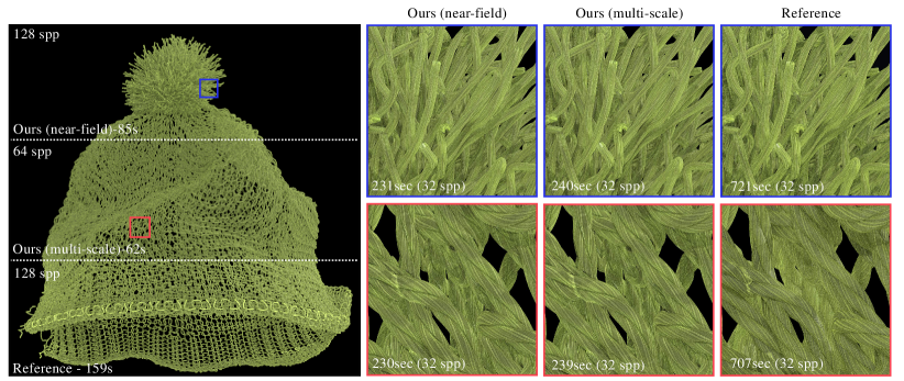
Significant speed-up and efficient memory usage: By employing our aggregated yarn-based appearance model, on-the-fly geometry realization, and efficient integration for multi-scale rendering, we achieve a remarkable 3-5 times reduction in rendering time and memory usage. This is compared to the work of Montazeri et al. (2020) —referred to as the ply-based model throughout the paper— while generating results of equal quality in close-up scenarios. Furthermore, our multi-scale model delivers an additional 20% speed-up for far-away renderings, maintaining equal quality. For a comprehensive comparison, please refer to Tab. LABEL:table_performance.
2. Related Work
Surface-based Models: Early cloth rendering used 2D mesh surfaces with BRDFs (Adabala et al., 2003; Irawan and Marschner, 2012; Sadeghi et al., 2013) or BTFs (Dana et al., 1999) for fast pipelines, but lacked faithful cloth geometry and fiber details essential for close-up and overall appearance in distance. These methods also overlooked light transmission, crucial for realism. Microfacet BRDF analysis by Ngan et al. (2005) revealed limitations of BRDF-based approaches and specifically examined the anisotropic nature of velvet fibers. In contrast, our method provides fine details for near-field views and accurate light transmission, addressing these shortcomings.
Volumetric Models: Volumetric models in cloth rendering focus on capturing the geometry of individual fibers. Inspired by the pioneering work of Kajiya and Kay (1989), these models employ micro-imaging techniques like CT scans to obtain precise fiber geometry. The Radiative Transport Equation (RTE) is then used to simulate light interactions within the cloth.
RTE was extended by Jakob et al. (2010) for anisotropic cloth by introducing direction-dependent scattering and attenuation to simulate light interactions through anisotropic media such as cloth. Further advancements were made proposing micro-appearance models (Zhao et al., 2011, 2012; Khungurn et al., 2015) which relied on the anisotropic RTE and CT images for highly accurate renderings, considering fiber-level interactions. However, volumetric models are slower, memory-intensive compared to surface-based models, and challenging for non-static cases due to detailed fiber geometry and light interactions and the use of a practical resolution of volumetric grids. A procedural on-the-fly approach addressed the need for pre-storing curves (Luan et al., 2017). Yet, acquiring data for volumetric representation techniques remains challenging. Our model offers comparable fidelity but is faster, treating the yarn as a whole and analytically aggregating the expensive fiber interactions.
Curve-based Models: Curve-based models depict cloth surfaces using fiber-modeled curves, utilizing Bi-directional Curve Scattering Distribution Functions (BCSDFs), originally introduced for hair strands by (Marschner et al., 2003). This approach has gained popularity for simulating the appearance of fur, hair, and cloth. Subsequent research has improved it by considering scattering events (Yan et al., 2015, 2017a; Zhu et al., 2022).
An alternative model, proposed by Irawan and Marschner (2012), is a yarn-based model, leveraging geometric information within yarns to represent cloth appearance. Fiber-based models (Khungurn et al., 2015), were later introduced to capture detailed cloth appearance considering the scattering of light off individual fibers. They have been further enhanced to include real-time capabilities through core fiber aggregation (Wu and Yuksel, 2017) and exploring the correlation between mechanical simulations and fiber appearance (Montazeri et al., 2021b). However, these models can be inefficient due to the slow construction and traversal of the hierarchy of a large number of fibers and the increased computational complexity of simulating light interactions between fibers.
To strike a balance, Montazeri et al. (2020) proposed a ply-based model for woven cloth which was later extended to knitted cloth (Montazeri et al., 2021a). In this model, individual plies are represented as curves and 1D textures are used to add fiber-level details. It successfully achieves a detailed appearance, ensuring energy conservation during scattering events (Zhu et al., 2022) without the need for a large volume hierarchy for fiber curves.
In Sec. 1, we contend that the ply-based model inadequately represents yarns, focusing on individual plies as explicit curves. Yarns typically consist of 3 to 12 plies, with 5-ply yarns being the most common (Zhao et al., 2012). While offering high quality in near-field views, it exhibits high variance in far-field due to inherent micro-structure details. To address the ply dependency issue, a new yarn model was proposed that offers ply-level details (Zhu et al., 2023). However, apart from the lack of fiber details, this model can be problematic in both geometry and shading: wrong ply geometry can be produced, especially from grazing angle; Sharp silhouette of plies and significant color mismatch may appear due to incorrect transparency in a dual-scattering (Yuksel, 2020) style shading. In contrast, our multi-scale yarn-based model offers a comprehensive solution, effectively managing varied ply counts with fiber details without impacting performance and accuracy across different viewing distances (§5).
3. Modeling Yarn Geometry
Preliminaries: While the geometric representation of cloth can be complex, its hierarchical structure allows for faithful representation at different scales. Cloth is made up of long strands of yarn, consisting of multiple intertwined plies and hundreds of micro-diameter twisted fibers.
3.1. Overview
In our model, we focus on accurately representing cloth by explicitly generating yarn curves while implicitly computing ply and fiber details. This approach achieves an efficient yet accurate depiction, particularly well-suited for near-field viewing. Previous models either lack sub-yarn details (Sadeghi et al., 2013), employ explicit fiber structures that are computationally intensive (Khungurn et al., 2015), or rely on explicit ply structures that are inefficient for multi-ply yarns (Montazeri et al., 2020, 2021a). In what follows, we describe our geometric representation approach for cloth and the implicit ray tracing technique we employ to accurately compute the ray intersections with the cloth sample.
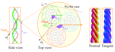
Our simplified geometric method takes a ray and a curved cylinder representing the yarn geometry as inputs. The outputs include the intersection point with the ply and the fiber’s canonical frame (normal and tangent) at that point as if the fiber has been intersected explicitly. In case the ray doesn’t find the intersection with the plies after hitting the yarn, a no-hit case is reported as an output.
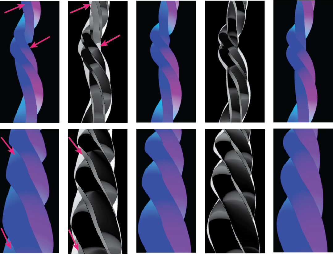
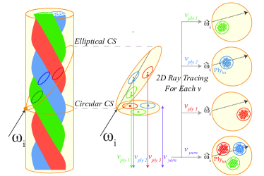
To achieve the ply hit point, we propose an implicit ray tracing by focusing on the elliptical cross-section of the yarn instead of traditional circular cross-sections, as compared in Fig. 4. To this end, we assume plies and fibers as curved cylindrical helices. Thus, a perpendicular cut through the yarn results in a circular and an angled cut yields an elliptical cross-section, which consists of conceptual ply and fiber circles. By implicitly tracing the ray and analyzing light interactions within the elliptical cross-section formed by the ray, we can extract relevant information about the ply and fibers without the need for complex ray tracing computations involving explicit ply and fiber curves. It is important to note that our novel implicit ray tracing on the elliptical cross-section is more accurate than the traditional circular cross-section perpendicular to the yarn axis (Yan et al., 2017b; Zhu et al., 2023) especially when viewed at grazing angles, as demonstrated in Fig. 3.
3.2. Explicit Yarns
To determine the intersection between the ray and the yarn geometry, we utilize the B-Spline Curve shape module in Mitsuba 3 (Jakob et al., 2022). The hit point computed for a curved cylinder has a UV map for the yarn, where represents the rotated angle between the yarn normal and a reference yarn normal at the root, referred to as azimuthal phase, and represents the length of the hit point from the root of the curve, referred to as longitudinal length. Additionally, we create a module for generating reference normals which are a static directions determined at every control point of the yarn by creating rotation minimization frames (Wang et al., 2008), depicted as a double line in Fig. 2. This fixed direction along the yarn curve is needed as the reference point to determine the azimuthal angles consistent through the animation.
3.3. Implicit Plies
Given the yarn hit point from §3.2, we employ a 2D ray tracing technique along the elliptical cross-section of the yarn cylinder to model the ply geometry. The previous works (Zhu et al., 2023) always rely on the circular cross-section immediately at the yarn hit to compute the ply intersection. However, the distance between this cross-section using the projected incident ray and the actual ply intersections with the ellipse plane formed along the incident ray is not negligible, especially at the grazing angle. Therefore, we utilize the more accurate elliptical cross-section strategy and visualize the comparison between elliptical and circular cross-sections by generating error maps of tangents for implicit plies. Tangent maps, based on the ply-centric model (Montazeri et al., 2020), illustrate the impact on yarn geometry when the incident ray is at an oblique angle and when the yarn is highly curved in Fig. 3.
The elliptical approach is challenging because as the ray advances through the yarn volume, the plys also change in position each following a helix. We use a lightweight Newtonian method to find the intersection of the ply center line (assumed as a helix) with the ellipse plane using only 3-5 steps. The initial step is the immediate cross-section at the yarn hit and we update the cross-section and closer to the final solution as illustrated in Fig. 4. Similar to the yarn scenario (§3.2), the intersected point on the ply is identified by the azimuthal phase and longitudinal length . This is done for each ply separately until we find the intersection of the ply helices with the ellipse plane.
In tracing for each step, we propose a smart trick by projecting the incident ray and finding the ply center at that specific circular cross-section. Then we intersect the computed ply center with the ellipse plane using a line following the yarn tangent direction. At the new position with a different we repeat the circular processing in the updated cross-section to find the ply center closer to the final solution. Once the ply center converges and no change in two consecutive iterations, the final solution of the helix and ellipse is returned as the hit-ply. This offers a fast tracing and please note the converged circular cross-section is different from the perpendicular circular cross-section at the yarn hit.
Once the appropriate positions of the ply centers are identified, we determine the ply closest to the yarn hit point. Once the appropriate ply hit is identified, we update its normal () and tangent () to incorporate the necessary ply-level geometry. At the hit point, the local ply tangent and ply normal are computed to form the ply geometry. The tangent vector is calculated using the first derivative of the 3D helix formula at the hit point, and the local ply normal is the vector pointing away from the ply center in the circular cross-section. If the ray does not intersect any plies, the ray is allowed to pass through the yarn cylinder.
3.4. Implicit Fibers
To model the fiber geometry, we adopt a precomputation-based approach first introduced by Montazeri et al. (2020). In this method, the ply cross-section is conceptualized as a collection of individual fiber centers, as illustrated in Fig. 2. Within this cross-section, we precompute fiber-level details, including normals and tangents, for the outermost fibers. These values are represented as a 1D texture map that wraps around the circumference of the ply and performs as a 1D hight-map to capture the visible fibers when viewed uniformly from the ply boundary.
While yarns typically consist of a few plies, each ply is usually composed of tens of fibers, resulting in a tightly packed representation. Therefore, the intersection point at the ply level serves as a reasonable approximation to the nearest fiber, and the necessary fiber-level details can be accessed directly from the texture without the need for additional implicit ray tracing. The resulting normal and tangent directions at the intersection points of the visible fibers are stored in a 1D texture that covers the outermost part of the cross-section. These precomputed values can be queried later using . Finally, by combining the values obtained from §3.3 and rotating the ply frame further based on the fiber frame, the final normal and tangent in global space can be computed as, and , respectively. where and are 1D perturbations from the precomputed textures, is the rotation of fibers.
Adding fiber migration: In §3.4, initially,
![[Uncaptioned image]](/html/2401.12724/assets/x4.png)
fibers are assumed to follow a regular helical configuration around ply centerlines with a constant radius. However, in reality, fibers exhibit radius variations, known as migration, often characterized by sinusoidal functions (Zhao et al., 2016). Our implicit ray tracing method, using exact 1D textures from the same fiber distribution in a circular cross-section, introduces an unwanted regular pattern lacking migration irregularities. To address this, we periodically and randomly switch between different 1D textures, formed by distinct fiber alignments in the cross-section. Interpolating between these textures mimics fiber disappearance and introduces irregularities, breaking the continuity.
4. Modeling Yarn Appearance
In this section, we discuss our approach to modeling the appearance of yarn, which complements the simplified geometry described in §3. Our yarn-based shading model extends the aggregated model first introduced in the ply-based model (Montazeri et al., 2020) to capture the appearance of a bundle of fibers.
4.1. BYSDF
The ply-based model provided a plausible shading model for individual plies, which consists of four lobes to capture specular and body components in both forward and backward directions. To adapt this model for yarns with implicit geometry (§3), three components require modification to accommodate interactions between plies. Only the immediate reflection component remains the same as the ply-based model.
Following the same notation from the literature, when an incident ray arrives at the surface of the yarn at point , it is divided into forward and backward portions. The backward component captures both the immediate reflection, which is part of the specular property (the first case in Eqn. 2), and the scattered light that exits the medium from the same side as the incident ray, referred to as the body property . Then, using the transmission component of (the second case in Eqn. 2), we sample a point on the yarn surface as the exit point, following the GGX distribution. Lastly, the forward component represents both the specularly transmitted light and the scattered light that continues in the forward direction. The illustration of our yarn-based appearance model is shown in Fig.5.
Assuming that we hit the yarn via a path starting from the camera at point . is simply the average of two lobes to capture specular and body but has to collect all contributions from the back side on different -s because the ray will refract towards different directions into a yarn. Therefore, it can be expressed as an integral with a kernel defined by over which is the part of surfaces that the refracted rays may cover. They can be formulated as follows:
| (1) |
Specular components: The specular components and represent the prominent highlights on the fabric surface when light reflects immediately or transmits through the fabric without being scattered. To model these specular lobes, we utilize a rough dielectric BSDF (Heitz, 2018; Walter et al., 2007) with a GGX distribution. The formulations for the specular components at points and are as follows:
| (2) |
| (3) |
where is the surface normal function, which is computed using the ply geometry at a given point and then further transformed based on the fiber alignments as described in §3. We denote this transformation as . represents the refractive index, is the Fresnel reflection coefficient, and are the normalized half vectors for two different cases, and is the Smith uncorrelated masking-shadowing function. The term represents the normal distribution function (NDF) with as the (anisotropic) roughness, and is the specular albedo.
Notably, a key distinction from the ply-based model (Montazeri et al., 2020) is the updated attenuation term , marked in gray. The term considers the attenuation of light between and using the Beer-Lambert law (Swinehart, 1962). In the ply-based model, explicit plies’ appearance is studied, and ray tracing multiple scattering events between plies is computationally intensive, particularly for yarns with numerous plies. In contrast, our yarn-based model focuses on modeling the overall yarn appearance, inherently incorporating interactions between plies more efficiently. This is accomplished by computing a new based on , the number of intersected plies along the elliptical cross-section for the projected ray. Thus, as a ray passes through the yarn cylinders, we update the attenuation term as to account for the attenuation by plies.
Body components: To capture the scattering behavior of the bundle of fibers as a whole and account for multiple scattering components, we utilize a diffuse-like distribution to approximate the sub-yarn scattering events (Yan et al., 2017a; Montazeri et al., 2020). At point , the body component is represented by a Lambertian term. On the other hand, additionally considers a Lommel-Seeliger (LS) term (Hanrahan and Krueger, 1993; Jensen et al., 2001) as a mix, to ensure the energy conservation. The expressions for and are as follows:
| (4) |
| (5) |
where is the body albedo and represents the reflected portion of the body energy and determined in correlation with the refracted albedo of . The terms and correspond to the ply-shadowing and fiber-shadowing functions, respectively. These functions account for the occlusion and shadowing effects caused by the plies and fibers and are queried from 1D textures as described next.
Self-Shadowing Components: To address the limitations of existing yarn-based shading models (Irawan and Marschner, 2012; Sadeghi et al., 2013), we introduce an additional shadowing component that considers the occlusion caused by one ply on another (). In ply-based method, the ply shadows are handled by the path tracer, thus it only has the fiber shadowing function. In our approach using implicit plies, we estimate the inter-ply shadows since they are part of our yarn appearance. This component is computed by calculating the occlusion ratio at the outermost hit points on the ply surface and storing them in 1D a texture map. This texture map behaves like a horizon map that wraps around the yarn cross-section circumference. The ply-shadowing module is pre-computed based on the procedural model of the ply structure described in §3.3 in the absence of fibers, and it provides full coverage of the yarn surface by sweeping along the yarn centerline.
In addition to the ply-shadowing term, we also consider a fiber-
![[Uncaptioned image]](/html/2401.12724/assets/x6.png)
shadowing term to account for self-shadowing caused by adjacent fibers as elaborated in §3.4. The multiplication of these two shadowing terms approximates the overall shadowing amount, compensating for the absence of explicit ply and fiber geometries. Although this shadowing component is computed in a 2D cross-section and does not capture the full 3D occlusion, our experiments have shown that it provides a reasonable estimation of the shadowed regions due to the regular procedural geometric representation of the yarn.
|
Importance Sampling:
Importance sampling optimizes light interaction in rendering. To manage energy conservation, we define parameter (), to normalize the energy ratio between specularity and scatterness of cloth. This parameter determines specularity energy, with the remaining energy allocated to the body component. The body component is further divided into reflection and transmission using another parameter (), computed based on the probability of the Fresnel term. After selecting the lobe based on energy allocation, importance sampling employs appropriate distributions. The GGX distribution is used for specular lobes, ensuring plausible modeling of their behavior. For diffuse-like components, a cosine-weighted distribution facilitates importance sampling. Details about energy conservation testing can be found in the supplementary material.
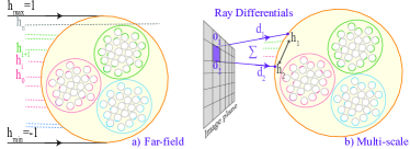
4.2. Multi-scale Feature
The described shading model is efficient for close-up rendering, capturing fiber details in the near field. However, when the camera moves away, covering multiple fibers or the entire yarn, the pixel coverage increases, causing variations in normal distributions and necessitating supersampling to mitigate noise. To address this, we introduce a multi-scale model inspired by Yan et al. (2017a), adapting shading computation based on pixel coverage for improved efficiency.
For close-up views covering individual fibers, the original near-field model (described in §4.1) is suitable, considering sub-yarn details. When the camera is distant, and the pixel footage spans the entire yarn, we employ a far-field model . In this case, we numerically integrate the BYSDF over the full azimuthal offset range from to . This integration captures the overall yarn appearance in the far field, significantly reducing the required ray samples compared to the near-field model. By numerically solving the integrals instead of relying on the path-tracer, we allow more efficient rendering using smaller light samples.
As illustrated in Fig. 6, the computation of the far-field model involves stratified Monte Carlo sampling of the range of and performing the integration accordingly. This approach ensures that the far-field model accounts for the global appearance of the yarn, and can be written as follows with normalization factor ,
| (6) |
To achieve a smooth transition between the near-field model () and the far-field model (), we introduce a multi-scale BYSDF that adapts based on the pixel coverage. The computation of the multi-scale BYSDF relies on ray differentials and , which define the azimuthal offset range covered by a specific pixel. The pixel coverage, represented by the range , determines the scale of the shading model. When the difference between and is small, indicating a close alignment, the multi-scale model performs similarly to the near-field model. These ray differentials are explained in detail in the supplementary and the final formulation of our multi-scale appearance model combines the near-field and far-field components as follows:
| (7) |
with being the normalization over . To approximate the multi-scale BYSDF (), again we use a Monte Carlo algorithm that involves sampling discrete values of within the queried azimuthal range . These samples are selected based on their distance to the reference azimuthal offset and are used to numerically compute the integrated geometry (§3) and the shading model (§4).
Specifically, note that the methods we use to compute and are still numerical. However, this approach is much more efficient than relying solely on a ray tracer with only the near-field model. We demonstrate this in 6.
To determine the aggregated geometry spanning this range, we compute the weighted average of the normal and tangent vectors of the visible fibers, which are precomputed as 1D texture maps. The weight () for each represents the distance to , considering the contribution of the samples based on their distribution. The aggregated normal () and tangent () vectors are then used in equations (2) and (4) to compute . The computation of and can be expressed as follows:
| (8) |
Similarly, to find the aggregated shadowing component covering the queried azimuthal range, we use the weighted average of the fiber-shadowing terms queried from the precomputed 1D texture map. Aggregated shadowed value accounts for the energy loss in the original near-field model due to the presence of the microstructure. Ignoring this term would lead to unwanted brightness, similar to the known issue in microfacet materials. Additionally, the roughness variable of the specular lobe must be also adjusted. Aggregated roughness is mapped linearly as a function of the azimuthal offset range to compensate for the absence of micro-geometries and the number of samples queried in that range. The updated is experimentally given by, , which naturally contributes to a rougher appearance.
| (9) |
Additional implementation details for the multi-scale feature are added in the supplementary.
5. Results
In the following section, we present the rendering results obtained using our practical BYSDF and conduct a comparative analysis with existing approaches. The reference model in this paper is the ply-based model proposed by Montazeri et al. (2020), which was evaluated against real photographs in the original paper. We use the differentiable setup in Mitsuba 3 to match the set of parameters of our model against the reference. The set of parameters and details regarding parameter fitting can be found in the supplementary. We also compare the BYSDF with the model by Khungurn et al. (2015) which to this end is known as the fiber-based reference as well as Zhu et al. (2023) as the recent yarn-based model. Our implementation of the geometric and appearance representation is integrated into the Mitsuba renderer (Jakob et al., 2022) as a custom integrator and material plugin. All scenes shown in the paper were rendered using an AMD Ryzen 9 7950X 16-core Processor 4.50 GHz.
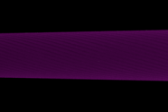
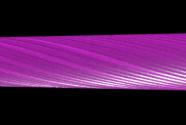
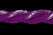
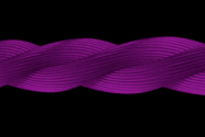
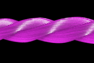
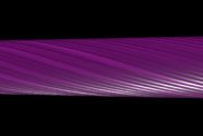
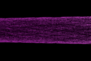
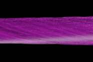
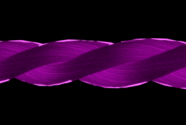
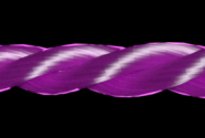
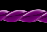
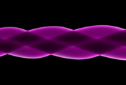
Single yarns: In the first set of results ( Fig. 7), we compare our yarn-based method to the ply-based reference as well as the previous models under three different lighting configurations: front lighting only, back lighting only, and both front and back lighting. Our yarn-based model, similar to the reference, handles reflection and transmission separately, which allows it to capture the complex appearance of the yarn more accurately compared to the fiber-based model that considers all individual fiber interactions (Khungurn et al., 2015). We observed that the fiber-based model can match the appearance of the reference model reasonably well under front lighting conditions, but it struggles to match the appearance when the lighting is changed to the back or when both front and back lighting are present, highlighting the limitations of its complex geometry representation. Furthermore, our model offers more accurate back-lighting due to the proper transmission sampling, while Zhu et al. (2023) showcases an unwanted sharp transparent silhouette from the plies in the back. This artifact arises because the refracted ray in their approach is employed without any sampling or perturbation; it is directly utilized as transmission, resulting in this visual discrepancy. Finally, our model demonstrates improved efficiency compared to the reference ply-based model (Montazeri et al., 2020), especially when dealing with yarns that have multiple plies.
Woven and knitted samples: Furthermore, we conducted a comparison between our rendering results and the reference for woven and knit samples to demonstrate that our yarn-based approach is capable of accurately reproducing the appearance of fabrics regardless of the manufacturing structures on a macro scale and reasonably matching with the ply-based reference. Fig. 9 showcases the comparison between Our BYSDF and the recent yarn-based model (Zhu et al., 2023). While our model captures the transmission light accurately, their model has difficulty with back lighting because of the lack of sampling as explained in Fig. 7. Besides, the overall appearance of their result is hard and cannot reproduce the softness of the reference cloth. In Fig. 10, the fiber-based model reasonably matches the reference only if we enforced the parameters for each of the three setups separately. Our model, however, is only fitted for front- and back-lighting setups and automatically matches the front-and-back lighting scene with the reference due to the reflection and transmission parameters being decoupled. Our model boasts about 6-time performance gain due to the simplified geometry in comparison to the fiber-based model. The yarn geometries of all three samples are taken from the dataset by Leaf et al. (2018) and the fiber curves are generated procedurally (Zhao et al., 2016) and shaded accordingly (Khungurn et al., 2015). Please refer to Table LABEL:table_performance for a detailed comparison.
Multi-scale results: In Fig. 6, we illustrate the three different modes of our model: a) In the near-field mode, the model is optimized for rendering when the camera is close to the fabric, and it accurately captures the fine details of the fibers and ply-level geometry. However, as the camera moves away, rendering using the near-field model becomes noisy and inefficient. b) To address this, we introduce the multi-scale mode, which offers a smooth transition between the near-field and far-field rendering. This model is able to adaptively match the appearance of far-away renderings using a significantly smaller number of samples per pixel (spp) compared to the near-field mode. c) In the far-field mode, the model is integrated over the entire yarn, capturing the macro-scale appearance of the fabric with no fiber detail. This mode is suitable when the camera is far away from the fabric and the pixel coverage spans more than the yarn width entirely. The geometry of the glove scene is taken from the yarn dataset by Yuksel et al. (Yuksel, 2020).
Please note that the far-field appearance in both cases is incorrect because, even when zoomed far away (left), a yarn is still much thicker than a pixel. As a result, the actual range of is much smaller than the range of [-1, 1] used for far-field rendering. Therefore, the far-field appearance should not be expected to match the other modes. However, the far-field mode still enables a significant reduction in the number of ray samples compared to the near-field mode. In essence, when the fabric is viewed from close-up (right), our multi-scale method should provide rendering performance comparable to the near-field mode. This is achieved by dynamically determining the number of ray samples proportional to the azimuthal offsets range (). On the other hand, when the fabric is viewed from far away, our method should be significantly more efficient than the near-field mode, as it allows for a substantial reduction in the number of required ray samples.
Please see the supplementary for the additional results.
6. Discussion and Conclusion
Limitations and future works: Our model adds fiber texture using 1D texture maps following the ply-based model (Montazeri et al., 2020). Ideally the implicit ray tracing along the elliptical yarn cross-section, employed for incorporating ply geometry, can be extended for a comprehensive solution to seamlessly integrate fiber details without the need for texture maps. Additionaly, the appearance of fabrics can include loose fibers sticking out, referred to as ”flyaways,” which are not integrated into our current framework. However, flyaways can be incorporated as future extensions by introducing random distributions and considering the lifespan of fibers.
Our model works for woven and knitted patterns, it would be interesting to explore an accurate model for fabrics featuring a bundle of protruding fibers, as seen in materials like velvet.
Conclusion: We have introduced BYSDF, a practical yarn-based model that efficiently captures the appearance of cloth. First, by reducing the complexity of geometry so the cost of ray tracing is lower, second, we avoid complex light transport between plies and fibers so the number of rays needed is smaller. Our model excels in rendering close-up views of cloth samples, known as the near field. We have also proposed an efficient solution for seamlessly integrating the geometry and appearance of cloth as the camera moves away from the object, enabling a smooth transition from the near field to the far field.
Our BYSDF model extends the reference ply-based model by computing an aggregated shading model at the yarn level, accurately reproducing the appearance of cloth and capturing the implicit geometries of ply and fiber. We have addressed the absence of explicit geometry by incorporating realistic shadowing effects. Compared to existing methods, our model offers a significant improvement in performance, providing high-fidelity results with faster rendering speed and reduced memory usage for near-field renderings. Additionally, our multi-scale solution allows for a substantial reduction in samples per pixel and offers enhanced efficiency for far-away renderings. We believe that our research will benefit a variety of offline graphics production for visual effects and feature animation, such as Weta Digital.
References
- (1)
- Adabala et al. (2003) Neeharika Adabala, Nadia Magnenat-Thalmann, and Guangzheng Fei. 2003. Real-time rendering of woven clothes. In Proceedings of the ACM symposium on Virtual reality software and technology. 41–47.
- Chiang et al. (2015) Matt Jen-Yuan Chiang, Benedikt Bitterli, Chuck Tappan, and Brent Burley. 2015. A Practical and Controllable Hair and Fur Model for Production Path Tracing. In ACM SIGGRAPH 2015 Talks (Los Angeles, California) (SIGGRAPH ’15). Association for Computing Machinery, New York, NY, USA, Article 23, 1 pages. https://doi.org/10.1145/2775280.2792559
- Dana et al. (1999) Kristin J. Dana, Bram van Ginneken, Shree K. Nayar, and Jan J. Koenderink. 1999. Reflectance and Texture of Real-World Surfaces. ACM Trans. Graph. 18, 1 (jan 1999), 1–34. https://doi.org/10.1145/300776.300778
- Hanrahan and Krueger (1993) Pat Hanrahan and Wolfgang Krueger. 1993. Reflection from Layered Surfaces Due to Subsurface Scattering. In Proceedings of the 20th Annual Conference on Computer Graphics and Interactive Techniques (SIGGRAPH ’93). Association for Computing Machinery, New York, NY, USA, 165–174. https://doi.org/10.1145/166117.166139
- Heitz (2018) Eric Heitz. 2018. Sampling the GGX Distribution of Visible Normals. Journal of Computer Graphics Techniques (JCGT) 7, 4 (30 November 2018), 1–13. http://jcgt.org/published/0007/04/01/
- Irawan and Marschner (2012) Piti Irawan and Steve Marschner. 2012. Specular reflection from woven cloth. ACM Transactions on Graphics (TOG) 31, 1 (2012), 1–20.
- Jakob et al. (2010) Wenzel Jakob, Adam Arbree, Jonathan T Moon, Kavita Bala, and Steve Marschner. 2010. A radiative transfer framework for rendering materials with anisotropic structure. In ACM SIGGRAPH 2010 papers. 1–13.
- Jakob et al. (2022) Wenzel Jakob, Sébastien Speierer, Nicolas Roussel, Merlin Nimier-David, Delio Vicini, Tizian Zeltner, Baptiste Nicolet, Miguel Crespo, Vincent Leroy, and Ziyi Zhang. 2022. Mitsuba 3 renderer. https://mitsuba-renderer.org.
- Jensen et al. (2001) Henrik Wann Jensen, Stephen R. Marschner, Marc Levoy, and Pat Hanrahan. 2001. A Practical Model for Subsurface Light Transport. In Proceedings of the 28th Annual Conference on Computer Graphics and Interactive Techniques (SIGGRAPH ’01). Association for Computing Machinery, New York, NY, USA, 511–518. https://doi.org/10.1145/383259.383319
- Kajiya and Kay (1989) J. T. Kajiya and T. L. Kay. 1989. Rendering Fur with Three Dimensional Textures. In Proceedings of the 16th Annual Conference on Computer Graphics and Interactive Techniques (SIGGRAPH ’89). Association for Computing Machinery, New York, NY, USA, 271–280. https://doi.org/10.1145/74333.74361
- Khungurn et al. (2015) Pramook Khungurn, Daniel Schroeder, Shuang Zhao, Kavita Bala, and Steve Marschner. 2015. Matching Real Fabrics with Micro-Appearance Models. ACM Trans. Graph. 35, 1 (2015), 1–1.
- Leaf et al. (2018) Jonathan Leaf, Rundong Wu, Eston Schweickart, Doug L. James, and Steve Marschner. 2018. Interactive Design of Yarn-Level Cloth Patterns. ACM Transactions on Graphics (Proceedings of SIGGRAPH Asia 2018) 37, 6 (11 2018). https://doi.org/10.1145/3272127.3275105
- Luan et al. (2017) Fujun Luan, Shuang Zhao, and Kavita Bala. 2017. Fiber-Level On-the-Fly Procedural Textiles. Comput. Graph. Forum 36, 4 (jul 2017), 123–135. https://doi.org/10.1111/cgf.13230
- Marschner et al. (2003) Stephen R Marschner, Henrik Wann Jensen, Mike Cammarano, Steve Worley, and Pat Hanrahan. 2003. Light scattering from human hair fibers. ACM Transactions on Graphics (TOG) 22, 3 (2003), 780–791.
- Montazeri et al. (2021a) Zahra Montazeri, Soren Gammelmark, Henrik W Jensen, and Shuang Zhao. 2021a. A Practical Ply-Based Appearance Modeling for Knitted Fabrics. arXiv preprint arXiv:2105.02475 (2021).
- Montazeri et al. (2020) Zahra Montazeri, Søren B Gammelmark, Shuang Zhao, and Henrik Wann Jensen. 2020. A practical ply-based appearance model of woven fabrics. ACM Transactions on Graphics (TOG) 39, 6 (2020), 1–13.
- Montazeri et al. (2021b) Zahra Montazeri, Chang Xiao, Yun Fei, Changxi Zheng, and Shuang Zhao. 2021b. Mechanics-Aware Modeling of Cloth Appearance. IEEE Transactions on Visualization and Computer Graphics (1 Jan. 2021), 137 – 150. https://doi.org/10.1109/TVCG.2019.2937301
- Ngan et al. (2005) Addy Ngan, Frédo Durand, and Wojciech Matusik. 2005. Experimental Analysis of BRDF Models. Rendering Techniques 2005, 16th (2005), 2.
- Sadeghi et al. (2013) Iman Sadeghi, Oleg Bisker, Joachim De Deken, and Henrik Wann Jensen. 2013. A practical microcylinder appearance model for cloth rendering. ACM Transactions on Graphics (TOG) 32, 2 (2013), 1–12.
- Swinehart (1962) D. F. Swinehart. 1962. The Beer-Lambert Law. Journal of Chemical Education 39, 7 (1962), 333. https://doi.org/10.1021/ed039p333 arXiv:https://doi.org/10.1021/ed039p333
- Walter et al. (2007) Bruce Walter, Stephen R. Marschner, Hongsong Li, and Kenneth E. Torrance. 2007. Microfacet Models for Refraction through Rough Surfaces. In Proceedings of the 18th Eurographics Conference on Rendering Techniques (EGSR’07). Eurographics Association, Goslar, DEU, 195–206.
- Wang et al. (2008) Wenping Wang, Bert Jüttler, Dayue Zheng, and Yang Liu. 2008. Computation of rotation minimizing frames. ACM Transactions on Graphics (TOG) 27, 1 (2008), 1–18.
- Wu and Yuksel (2017) Kui Wu and Cem Yuksel. 2017. Real-Time Fiber-Level Cloth Rendering. In Proceedings of the 21st ACM SIGGRAPH Symposium on Interactive 3D Graphics and Games (San Francisco, California) (I3D ’17). Association for Computing Machinery, New York, NY, USA, Article 5, 8 pages. https://doi.org/10.1145/3023368.3023372
- Yan et al. (2017a) Ling-Qi Yan, Henrik Wann Jensen, and Ravi Ramamoorthi. 2017a. An Efficient and Practical Near and Far Field Fur Reflectance Model. ACM Transactions on Graphics (Proceedings of SIGGRAPH 2017) 36, 4 (2017).
- Yan et al. (2017b) Ling-Qi Yan, Weilun Sun, Henrik Wann Jensen, and Ravi Ramamoorthi. 2017b. A BSSRDF Model for Efficient Rendering of Fur with Global Illumination. ACM Transactions on Graphics (Proceedings of SIGGRAPH Asia 2017) 36, 6 (2017).
- Yan et al. (2015) Ling-Qi Yan, Chi-Wei Tseng, Henrik Wann Jensen, and Ravi Ramamoorthi. 2015. Physically-accurate fur reflectance: Modeling, measurement and rendering. ACM Transactions on Graphics (TOG) 34, 6 (2015), 1–13.
- Yuksel (2020) Cem Yuksel. 2020. Yarn-level Cloth Models. http://www.cemyuksel.com/research/yarnmodels.
- Zhao et al. (2011) Shuang Zhao, Wenzel Jakob, Steve Marschner, and Kavita Bala. 2011. Building volumetric appearance models of fabric using micro CT imaging. ACM Transactions on Graphics (TOG) 30, 4 (2011), 1–10.
- Zhao et al. (2012) Shuang Zhao, Wenzel Jakob, Steve Marschner, and Kavita Bala. 2012. Structure-aware synthesis for predictive woven fabric appearance. ACM Transactions on Graphics (TOG) 31, 4 (2012), 1–10.
- Zhao et al. (2016) Shuang Zhao, Fujun Luan, and Kavita Bala. 2016. Fitting Procedural Yarn Models for Realistic Cloth Rendering. ACM Trans. Graph. 35, 4, Article 51 (jul 2016), 11 pages. https://doi.org/10.1145/2897824.2925932
- Zhu et al. (2023) Junqiu Zhu, Zahra Montazeri, Jean-Marie Aubry, Ling-Qi Yan, and Andrea Weidlich. 2023. A Practical and Hierarchical Yarn-based Shading Model for Cloth. Computer Graphics Forum 42, 4 (2023), 11 pages. https://doi.org/10.1111/cgf.14894
- Zhu et al. (2022) Junqiu Zhu, Sizhe Zhao, Lu Wang, Yanning Xu, and Ling-Qi Yan. 2022. Practical level-of-detail aggregation of fur appearance. ACM Transactions on Graphics (TOG) 41, 4 (2022), 1–17.
| Front lit | Back lit | Front & back lit | Front lit | Back lit | Front & back lit | |
| Ours |

|
 |
 |
|
 |
 |
|---|---|---|---|---|---|---|
| Reference |
|
 |
 |
|
 |
 |
| Khung’15 |
|
 |
 |
|
 |
 |
| Zhu’23 |

|
 |
 |
|
 |
 |
| ————– a) Single-ply ————–—————————- | ————– b) Three-ply ————– —————————- | |||||
 |
 |
 |
 |
 |
 |
 |
 |
 |
 |
 |
 |
| a) Near-field | b) Multi-scale | c) Far-field | a) Near-field | b) Multi-scale | c) Far-field |
| Front lit | Back lit | Front & back lit | Front lit | Back lit | Front & back lit | |
| Ours |
|
|
||||
|---|---|---|---|---|---|---|
| Reference |
|
|
||||
| Zhu’23 |
|
|
||||
| ————– Zoom-out ————– | ————– Zoom-in ————– | |||||
| Front lit | Back lit | Front & back lit | Front lit | Back lit | Front & back lit | ||
| Ours |
|
|
a) Woven basket | ||||
| Reference |
|
|
|||||
| Khung’15 |
|
|
|||||
| Ours |
|
 |
|
b) Woven Satin | |||
| Reference |
|
|
|||||
| Khung’15 |
|
|
|||||
| ————– Zoom-out ————– | ————– Zoom-in ————– | ||||||