Fault tolerance of stabilizer channels
Abstract
Stabilizer channels, which are stabilizer circuits that implement logical operations while mapping from an input stabilizer code to an output stabilizer code, are ubiquitous for fault tolerant quantum computing not just with surface codes, but with general LDPC codes and Floquet codes. We introduce a rigorous and general formalism to analyze the fault tolerance properties of any stabilizer channel under a broad class of noise models. We provide rigorous but easy-to-work-with definitions and algorithms for the fault distance and hook faults for stabilizer channels. Additionally, we establish necessary conditions such that channel composition preserves the fault distance. We apply our framework to design and analyze fault tolerant stabilizer channels for surface codes, revealing novel aspects of fault tolerant circuits.
I Motivation and overview
Large-scale quantum computers built from inevitably imperfect hardware will require some form of fault tolerance to reliably implement large computations. The vast majority of approaches that have been considered to build fault tolerant quantum computation rely on protecting the information by storing it in stabilizer codes Gottesman (1997). The computation proceeds by applying carefully designed circuits on the hardware that, with appropriate classical processing, reliably apply logical operations to the encoded states even when faults occur. We call these fault-tolerant circuits which implement logical operations while mapping from an input stabilizer code to an output stabilizer code channels (note that the input and output stabilizer codes do not need to be the same). Such channels fall into two classes: stabilizer channels which are implemented by so-called ‘stabilizer operations’ (preparations and measurements in the Pauli bases, along with Clifford unitaries) and non-stabilizer channels which also make use of some non-stabilizer operations, for example to produce encoded magic states Knill (2004); Bravyi and Kitaev (2005). In this work, we focus on stabilizer channels.
The class of stabilizer channels is ubiquitous in the field of quantum error correction (QEC). It is clear that this class includes a wide range of fault tolerance techniques that are typically defined in terms of stabilizer circuits, including stabilizer extraction, lattice surgery Horsman et al. (2012), code deformation, and transverse Clifford gates. Moreover, by considering explicit circuit implementations, one can see that this class also includes many logical operations that are more commonly thought of from a topological viewpoint of topological stabilizer codes such as braiding punctures Raussendorf et al. (2006); Raussendorf and Harrington (2007); Raussendorf et al. (2007); Bombin and Martin-Delgado (2008, 2009); Fowler et al. (2009, 2012) and braiding twist defects Bombin (2010); Hastings and Geller (2014). Since Pauli-based subsystem codes and Floquet codes have information encoded in a stabilizer code at each moment in time, stabilizer channels also include fault-tolerant error correction and most logical gates for these more exotic code families.
As quantum computing hardware advances towards the quantum error correction era, it is becoming increasingly important to make high-level descriptions of fault-tolerant circuits more explicit and ensure circuits are fault tolerant with respect to more specific noise models. By moving from simple phenomenological models of noise Dennis et al. (2002) to more explicit circuit noise Wang et al. (2009), more accurate overhead estimates for different fault tolerance schemes are possible Fowler et al. (2012); Beverland et al. (2021); Das et al. (2020); Chamberland et al. (2020a). In some cases, carefully specifying details can highlight practical limitations of promising ideas e.g. boundaries are problematic for the existing proposals for biased surface codes Higgott et al. (2022). There is a miscellany of approaches that the QEC community currently uses to argue that a given stabilizer channel to perform some task is fault tolerant. Some approaches are very high-level, for example using assymptotic scaling results hold in order to prove the existence of a finite threshold Brown (2020). Other approaches are very idealized - for example considering a stabilizer channel in isolation, with a perfect input state, and not considering the reality that many noisy channels will be applied in sequence. Further approaches rely on numerics - sampling noise events at random without necessarily proving correctness Gehér et al. (2023). In the coming years there will undoubtedly continue to be many more fault-tolerant channels proposed, for both the well-established codes such as the surface codes and color codes, but also for exciting new LDPC code families Kovalev and Pryadko (2013); Tillich and Zémor (2013) which have been found to be promising for practical application Bravyi et al. (2023); Tremblay et al. (2021). This motivates us in this work to develop tools to rigorously, define, analyze and design fault-tolerant stabilizer channels. In what follows, we summarize the main contributions in this paper.
Formalism.— After reviewing the basic properties of stabilizer codes and channels in Section II, we provide a rigorous and general formalism to analyze the fault tolerance properties of any stabilizer channel under a broad class of noise models in Section III. Our formalism relies upon and connects together many previous works, complimenting existing formalisms that focus on topological codes Dennis et al. (2002); Brown et al. (2017); Bombin et al. (2021). By not requiring any geometric locality, our formalism applies to a very wide range of fault-tolerant protocols including general quantum LDPC codes Gottesman (2013); Tillich and Zémor (2013); Breuckmann and Eberhardt (2021); Kovalev and Pryadko (2013); Panteleev and Kalachev (2021); Lin and Pryadko (2023); Wang et al. (2023), Floquet codes Hastings and Haah (2021); Davydova et al. (2023); Aasen et al. (2022); Higgott and Breuckmann (2023) and space-time codes Delfosse and Paetznick (2023a); Gottesman (2022). Among other things, we provide rigorous definitions of the fault distance Bombin et al. (2021) in terms of a general form circuit that captures the channel’s logical action Kliuchnikov et al. (2023), and of hook faults Dennis et al. (2002) for general stabilizer channels.
Analytic analysis.— In Section IV, we first observe that any stabilizer channel can be re-expressed as a sequence of code deformation rounds. Leveraging the computation in Ref. Kliuchnikov et al. (2023) of the logical action of a single code deformation round allows us to analytically describe stabilizer channels in terms of the stabilizer groups of the input and output codes, and the group of measurements in each deformation round.
Channel composition.— In Section V, we provide explicit sufficient conditions for a set of stabilizer channels that ensure that larger channels formed by composing them together will inherit their fault tolerance properties. It is possible to extend our analysis of stabilizer channels to include compositions with fault-tolerant non-stabilizer states prepared by techniques that are not stabilizer channels (such as magic state distillation or code switching). This extension, outlined in Section VIII, is quite straightforward since the framework puts no restrictions on the input states to stabilizer channels.
Algorithms.— We provide algorithms in Section VI to compute the fault distance of any stabilizer channel, which is similar to algorithms in Refs. Gidney (2021); Breuckmann et al. (2017), and to identify problematic hook faults in a channel. We find the latter to be very useful in the practical design of fault-tolerant stabilizer channels. These algorithms apply when the channel check matrices are graph-like. We also discuss efficient algorithms for determining if a channel matrix is graph-like and various approaches that help bound the fault distance for channels with non-graph-like channel check matrices.
Examples.— In Section VII, we illustrate these ideas by walking through the design and fault-tolerance analysis of two example channels in surface codes. The first example is the lattice surgery operation to implement a logical measurement between a pair of code patches, which recovers the standard analysis in Refs. Chamberland and Campbell (2022). The second example is the logical Hadamard on a single patch, leaving it in an adjacent location. While we developed our Hadamard implementation independently of the recent work Gehér et al. (2023), we point out that our approach is quite similar to the first of the two examples therein, although our circuit-level implementation has a worse depth than theirs (asymptotically , compared with their error correction cycles for distance ).
These examples, particularly the Hadamard, highlight a number of novel features that can arise in fault-tolerant circuit design (some of which were also highlighted in Ref. Gehér et al. (2023)). In particular, we find that stabilizer extraction circuits exhibit:
-
1.
Spatial variation.— Our Hadamard channel involves some irregular surface code patches in intermediate steps which require non-uniform stabilizer extraction circuits (for example min-weight X type logical operators may be horizontal in one region of the lattice, and vertical in another).
-
2.
Temporal variation.— Due to the existence of ‘diagonal’ hook faults in the circuit-level syndrome graph, logical operators can be deformed in the time dimension without increasing their weight. This results in a phenomenon where the same stabilizer code in our channel must be measured using different circuits at different times to avoid hook errors that align with logical operators that have been deformed from other times.
Lastly, we conclude in Section VIII, highlighting a number of future directions.
II Basic definitions
Here we set notation and review some important material that is relevant for this work.
II.1 Stabilizer codes
We find it convenient to use the notation that for Pauli operators and , the commutator if and commute and otherwise. We write the set of integers from to as , and the set of integers from to as . We write to denote the set of Pauli operators that commute with all elements of a Pauli operator set .
If , we say that the Pauli operator stabilizes the state , and also that the state is stabilized by the Pauli operator . We say that a group of commuting operators stabilizes a state if all elements of stabilize . An Abelian Pauli group specifies a stabilizer code, where the codespace consists of those states which are stabilized by . Measuring a complete set of generators of the stabilizer group produces a set of outcomes that we call the syndrome, which is trivial if the state is in the codespace. We also define the syndrome of a Pauli operator with respect to a complete set of generators of a stabilizer group , which is the list .
Given a Pauli group and a Pauli operator , we often write , which denotes the set . Given a pair of Pauli groups and , we often write , which denotes the set .
For the measurement of Hermitian Pauli operators, we use the convention that the possible outcomes are labeled by and (not ). We often consider the addition of measurement outcomes or sets of measurement outcomes, which is always performed modulo two unless otherwise stated.
II.2 Stabilizer circuits and general form
In this work, we consider circuits built of elements of an explicit instruction set . We require the operations in are stabilizer operations:
-
•
preparations of qubits in the computational basis,
-
•
non-destructive measurements of Pauli operators,
-
•
destructive measurements of single-qubit Pauli operators,
-
•
Clifford unitaries,
-
•
the generation of classical random bits,
-
•
conditional Pauli operations controlled on the parities of prior measurement outcomes and random bits.
The instruction set could in principle consist of of all possible stabilizer operations, but it may be useful to further restrict to those which match the capabilities of a specific hardware platform. For example may contain all single-qubit stabilizer operations and CNOT gates between specified pairs of qubits.
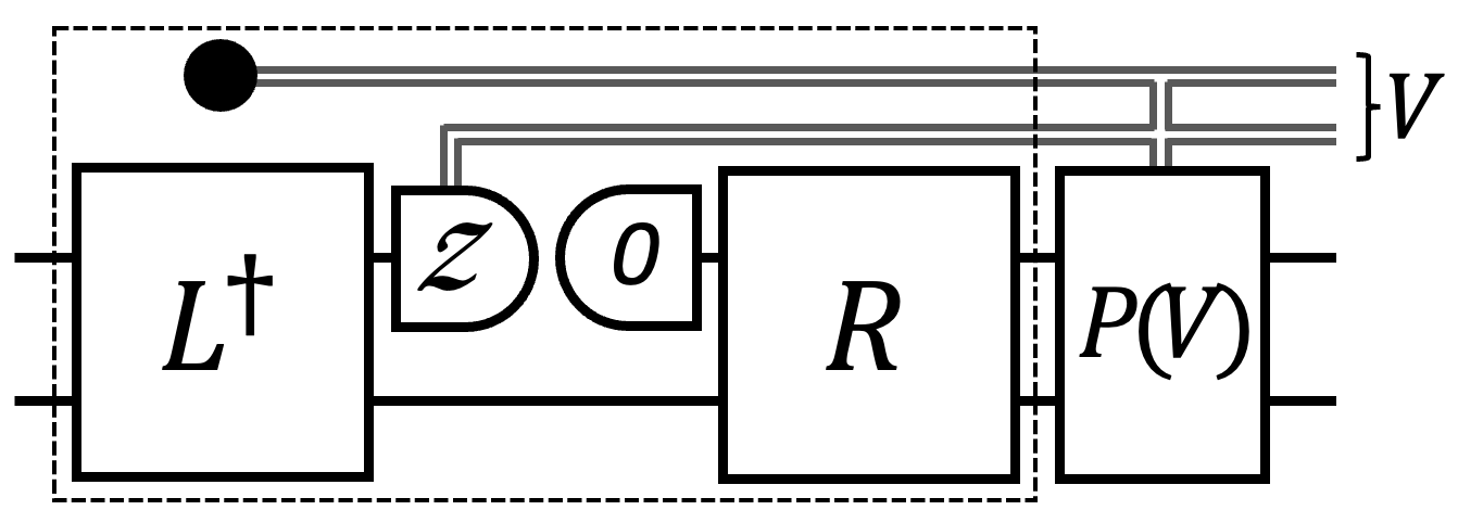
The operations in a stabilizer circuit occur at specified time steps, with compatible sets of operations being allowed in the same time step. (Note that precisely which sets of operations are considered compatible can depend on the setting, such as the capabilities of a hardware platform that the circuit is to be run on). We find it convenient to assign a specific sequence to all the operations in the circuit, which respects the ordering of time steps such that operations in the same time step of the circuit form a consecutive subsequence. We call the sequence of measurement outcomes and random bits produced by the circuit the circuit outcome vector. In Ref. Kliuchnikov et al. (2023), it is shown that any stabilizer circuit is equivalent to a simple general form circuit as shown in Fig. 1. By equivalent we mean that when both circuits are fed the same input state , then the state output by when its outcome vector is is the same as the state output by when its outcome vector is , for some known (affine) relation between and . As we will see, this general form is particularly helpful in characterizing and analyzing the logical action of stabilizer channels.
We include the conditional Paulis in italics in the list of stabilizer operations because in this work we treat them differently from the other stabilizer operations. In particular, we take the stabilizer circuit to be specified by the other stabilizer operations it contains, and we include or remove conditional Paulis at our convenience. This is because any conditional Paulis can be done off-line (by a Pauli-frame update) and/or postponed to the end of the stabilizer circuit without changing any of the circuit’s other instructions. Moreover, given a general form circuit for a stabilizer circuit, changing the circuit’s conditional Paulis only results in a change of the conditional Paulis of the general form circuit.
II.3 Stabilizer channels
Following the language of Ref. Bombin et al. (2021), we say that a stabilizer circuit is a stabilizer channel from to if, for any input state encoded in and for every possible channel outcome vector, it outputs a state encoded in . Note that to achieve this for all outcome vectors, a circuit will typically make use of carefully chosen conditional Paulis. Unless otherwise stated, we will assume throughout this work that all conditional Paulis are placed at the end of the stabilizer channel as shown in Fig. 2(a).
Given a stabilizer channel from to , it is natural to ask what logical action it has on the encoded information. To make the logical action of the channel uniquely defined, we must specify an explicit logical basis for each of and , which can be achieved by providing encoding Cliffords and for the input and output codes. An encoding Clifford for a -qubit stabilizer code maps and for to a basis of logical operator representatives, while it maps for to a set of independent stabilizer generators of the code. The logical action of a stabilizer circuit can then be succinctly characterized by finding a general form circuit equivalent to the composite stabilizer circuit formed by sandwiching between encoding and unencoding Cliffords for the input and output code as shown in Fig. 2(b). An appropriate choice of conditional Paulis at the end of the stabilizer channel yields the simple logical action general form shown, with no random bits or conditional Paulis. One such choice is to use the conditional Paulis obtained from finding a general form for the circuit formed by the ancilla state preparation, and the unconditional part of the stabilizer circuit. An efficient algorithm exists to find a general form for any stabilizer channel Kliuchnikov et al. (2023).
(a) (b)
(b)
We will make use of the following concepts and definitions. There is a natural correspondence between a Clifford unitary and the symplectic basis for qubits: . We say that a symplectic Pauli basis respects a stabilizer group if the basis contains a complete set of generators for . The encoding Cliffords and thereby specify the symplectic Pauli bases and which in turn respect and . A symplectic basis that respects the code with stabilizer group is a convenient tool for determining a complete set of logical operators of . A symplectic basis can be used to define a symplectic basis for the logical operators of using a simple two-step procedure. First remove all anti-commuting pairs from the basis for which one of the elements in the pair is in , second multiply all the remaining elements by . We omit the subscript in when the code is clear from the context.

The simplest example of a stabilizer channel is the trivial circuit. However, even though the circuit itself is trivial, when it is viewed as a channel with respect to specified input and output code bases it can have some non-trivial logical action if the two codes or their bases are different as shown in Fig. 3. We call this a code basis conversion channel. The parameters of a code basis conversion channel must satisfy certain properties. The stabilizer group of the output code must be contained in that of the input code. The unitary specifying the logical action must map each independent logical operator of from to in , where is the number of the independent generators of . Another condition on concerns the ordered set formed by taking and removing all anti-commuting pairs that have any of the elements in and multiplying the remaining pairs by . Then must map the logical operators in this set to from where is the number of logical qubits in .
III Fault tolerance definitions
In this section we consider the effect of noise on stabilizer channels and define key objects that we will work with later. Most of Section III.1 and Section III.2 consist of standard definitions for noise and decoding respectively, except that in Section III.2 we introduce a new definition for the logical failure of an arbitrary stabilizer channel in terms of the logical general form circuit. In Section III.3, we use this defintion to define a fault distance for the channel and prove that this implies that fault configurations with weight up to half the distance can be corrected. In Section III.4 we provide a formal general definition for hook faults which is useful for designing fault-tolerant channels.
Throughout this section we consider a stabilizer channel with an observed outcome vector from an input code with stabilizer group to an output code with stabilizer group , with respect to Pauli bases and . The logical action of the channel is captured by the general form circuit as in Fig. 8 with Clifford unitaries , and the outcomes of the logical measurements being encoded in a linear outcome function , where is the fault-free outcome vector (which may differ from the observed outcome vector due to noise). The following concepts will be used throughout this section.
Extended outcome vectors.— In the remainder of this section we will work with an extended version of the observed circuit outcome vector , where is the syndrome of the output code at the end of the channel. contains all of the information available to a decoder to perform error correction, which can include not only the outcomes that are observed in the channel itself, but also extra information that could potentially be obtained by acting on the state output by the channel. This extra information is at most that which is contained in , but in practice is likely to be noisy. Here we include with no noise, which is equivalent to the standard practice of including a ‘perfect round’ of syndrome extraction at the end of the channel. It is important to take care that this perfect output syndrome information does not lead to spurious analysis results, and we will return to this point in Section V when considering the composition of channels. For notational convenience, unless otherwise stated, we use extended versions of outcome vectors from here on but drop the ‘extended’ descriptor and write rather than .
III.1 Independent stochastic Pauli noise
In this work we assume noise occurs according to an independent stochastic Pauli noise model, whereby each operation in the circuit has an associated set of allowed faults, each of which occurs independently with some fixed probability. Each fault consists of the application of a specific Pauli operator to the physical qubits after the instruction, and flips of specific measurement outcomes. We assume that conditional Pauli operations never fail, and that they are applied at the end of the circuit. This assumption is justified because conditional Paulis can be applied offline by a Pauli-frame update and because the circuit, including any faults, is built from Stabilizer operations. Note that although the conditional Paulis are fault-free, whether or not they are applied can be flipped by faults which change the bitstring upon which they are controlled.
For each operation in , and for each fault it can experience according to the noise model, we assign an element to the elementary fault set . For each element of , we specify the probability that the elementary fault occurs, and its fault effect, which is the effect the fault has on the channel. The fault effect consists of the residual error Pauli which is applied to the qubits at the end of the stabilizer channel as a result of the fault, and the residual outcome flip bitstring which specifies how the channel outcome vector is modified to as a result of the elementary fault. Both and can be calculated for a given fault by inserting the fault into the stabilizer circuit, and propagating it to the end. In Section III.2 we will put some restrictions on the elementary fault set.
Multiple elementary faults can occur together, forming a fault configuration which is a subset . Since elementary faults are sampled independently from according to their probabilities, which forms a fault configuration with probability , which is the probability that those elementary faults in occur, and all elementary faults in do not. For any fault configuration , we define the residual error from the product of the residual errors of each elementary fault in , and the residual outcome flip by taking the sum over the residual outcome flips of each elementary fault in .
We also find it useful to define the effect of a Pauli error acting on the input qubits: and are the residual error at the end of the channel and residual outcome flip that would occur if was applied at the start of the channel without any faults.
We can associate a weight with each fault configuration. Unless otherwise stated, we take for every fault configuration , so that . We assume throughout this paper that the weights of all elementary faults (and therefore all faults) are non-negative. At times, we will set all weights to have unit weight (and will clearly state when doing so). This is useful in some analysis since if for example all elementary faults occur with a probability proportional to , then when assuming unit weights, the probability of some fault occurring is .
Our analysis in this paper holds for any independent stochastic Pauli noise model, but we will often refer to the following standard circuit noise model.
Circuit noise.— The instruction set consists of arbitrary single-qubit stabilizer operations, and arbitrary two-qubit stabilizer operations on specified pairs of qubits. We also allow arbitrary conditional Paulis. The faults are then:
-
•
Three faults for each each single-qubit instruction. Each of occurs with probability .
-
•
Fifteen faults for each two-qubit instruction (each of which is a non-trivial two-qubit Pauli). Each occurs with probability .
-
•
An outcome flip of each measurement instruction, which occurs with probability .
There are a number of variants of circuit noise models which are used in the literature which can be captured by slight modifications of the parameters in the above models. For example, some models are phrased in terms of exclusive rather than independent events (for example when an idle qubit failure occurs some models say that either an , or a or a error occurs). The standard exclusive phenomenological and circuit noise models can be re-expressed as independent stochastic Pauli noise models of the type here with specific fault probability values Chao et al. (2020). The allowed multi-qubit operations should be informed by hardware constraints, and this connectivity will have a significant impact on the details of circuits that can be implemented Chamberland et al. (2020b); Chao et al. (2020); Tremblay et al. (2021).
When analysing circuit noise, we also consider restricted circuit noise where the Pauli faults that follow one or two-qubit instructions are restricted to a subset of the three or the fifteen faults correspondingly.
III.2 Error correction
Here we primarily review some standard material on fault-tolerant quantum error correction for stabilizer channels, although we point the expert reader to our definition of undetectable fault configurations which is new. Many quantum error correction analyses focus on the scenario of memory where the goal is to fault-tolerantly store information, and do not address subtleties that can arise when the goal is instead to fault-tolerantly perform logical operations including measuring out some logical qubits. Here we use the general form circuit to capture the logical action, which complements the approach in Ref. Bombin et al. (2021) where the stabilizers of the Choi state are used.
In what follows, we will use the convention that the fault-free channel outcome vector is , and that given a fault configuration , and an input Pauli error , the observed channel outcome vector is , and the output Pauli error at the end of the channel is .
Channel checks.— Each channel check is either a parity (or the parity plus one) of a subset of elements of the channel outcome vector , with the property that its value is zero for every possible fault-free channel outcome vector . The sum of two checks is also a check, such that the checks form a vector space over . We use to denote a complete basis of channel checks. Note that the checks are defined without any reference to the noise model - they are a property of the channel irrespective of the kind of noise it undergoes. We define the syndrome to be the observed outcomes of the checks from .
Note that any fault-free outcome vector has trivial syndrome , and as such, . We assume that the syndrome contains all information used by the decoding algorithm to perform error correction. We can think of as an organized and potentially compressed representation of the data contained in which retains information about faults in the channel in a form that is conveniently consumed by the decoder. Different choices of check bases for the check space, while containing equivalent information, may be more or less convenient for decoding purposes.
Undetectable fault configurations.— We say that a fault configuration is undetectable if it has trivial syndrome, i.e. if . Note that since is included at the end of , the residual error for an undetectable fault must be a logical operator with respect to the output code basis , which we write as . We write the logical action of the fault as the bitstring , where and are the bitstrings that uniquely define the effect of on the logical action of the channel as defined in Fig. 4.
If is undetectable and has trivial logical action we say it is trivial. We say two fault configurations and are equivalent iff and .

Minimum-weight decoding.— In this work we assume the minimum-weight (MW) decoder , which finds a lowest-weight fault configuration which matches the observed channel syndrome . This is a most-probable fault configuration with the observed syndrome. A MW decoder may not be the optimal decoder, because the latter requires finding the most probable set of equivalent fault configurations. From , we can obtain the Pauli correction to be applied to the data qubits at the end of the channel and also a corrected version of the channel outcome that is used to obtain the logical outcome via . We will assume that the decoder is deterministic, such that the same correction is produced for a given syndrome , and we also that when the syndrome is trivial, is also trivial.
In the presence of noise, error correction is first applied, producing a fault configuration . This defines a corrected syndrome the corrected outcomes , for which all channel checks are satisfied. The overall logical action of the faults and error correction is then , and we say that error correction has succeeded if this is trivial and that it has failed otherwise. Since the logical outcome is obtained via , this ensures that we can use any choice of logical outcome function , because all the choices of are equivalent up to checks and after the outcomes are corrected, all the checks are zero.
Restrictions on the elementary fault set.— We can use some of the above definitions to impose useful restrictions on the elementary fault set . Firstly, we exclude undetectable elementary faults from , since they either have no effect on quantum error correction if their logical action is trivial or render quantum error correction futile otherwise. When convenient, we can furthermore assume that each elementary fault in has a unique effect pair . Note that if this is not the case for a given elementary fault set, we can modify it to enforce this condition by retaining only one elementary fault in with a particular effect . When doing this, the assigned to the retained elementary fault in the new elementary fault set is obtained from the sum over the probabilities of all combinations of an odd number of the equivalent elementary faults occurring in the original elementary fault set.
Matrix representations.— It is often convenient to represent a fault as a vector that we call a fault vector. Motivated by this definition, we use to represent the symmetric difference of two faults. Similarly, we represent an input Pauli error as an input error vector , which is expressed in the input code basis . We can then represent the linear dependence of checks on fault vectors as a channel check matrix defined via the equation . Every undetectable fault configuration corresponds to an element of the kernel of . Similarly, it is convenient to represent the linear dependence of logical action of fault configurations on fault vectors as a logical effect matrix defined via the equation . Every trivial fault configuration corresponds to of the kernels of and , and non-trivial undetectable fault configuration corresponds to in the kernels of and not in the kernel of .
III.3 Fault distance
The fault distance tells us how many faults can be corrected in a channel.
Definition III.1 (Fault distance).
Consider a stabilizer channel affected by a stochastic Pauli noise with elementary fault set . The fault distance is the minimum weight of a non-trivial undetectable fault configuration of , that is, the minimum weight of an element of the kernel of the channel check matrix that is not in the kernel of the logical effect matrix .
First, we show that the channel achieves its fault distance on a simple fault configuration, where we say that a fault configuration is simple if there is no undetectable fault configuration that is a proper subset of . Suppose that the fault configuration achieving the distance is not simple. We can represent it as a disjoint union of two undetectable fault configurations: . Consider the case when the channel distance is greater than zero. Suppose that is a non-trivial undetectable fault configuration; then, its weight must be the same as that of . For this reason, must be a weight-zero fault configuration and, therefore, trivial. Otherwise, this would contradict the minimal weight of a non-trivial undetectable fault configuration being positive. Therefore, we can replace with a non-trivial undetectable fault configuration of strictly smaller size. A similar argument applies when is a non-trivial undetectable fault configuration. The second case is when the channel distance is zero. Both and have a weight of zero. If is a non-trivial undetectable fault configuration, we can replace with a non-trivial undetectable fault configuration of strictly smaller size. A similar argument applies when is a non-trivial undetectable fault configuration. We can continue this process until we obtain a simple non-trivial undetectable fault configuration.
Next we show an important implication that the fault distance of a channel has on its error correction properties. We assume that the MW decoder has access to the channel checks and the output syndrome of the channel 111This is equivalent to appending a perfect round of syndrome extraction to the end of the channel and extending channel checks with the perfect round outcomes.. This assumption is motivated by the fact that the channel is usually a part of a larger computation and the later steps of the computation can be used to infer the output code syndrome. With the access to the output code syndrome, the MW decoder can correct any error with weight less than . To see this, suppose that a fault configuration occurs with syndrome and output code syndrome . The MW decoder will output a minimum weight fault configuration , where , and . The fault configuration is undetectable and has weight less than and is therefore trivial (since is less than ). For this reason, fault configurations and have the same logical action and we can correct by applying the correction .
Now we consider the lowest weight errors that lead to failure. Given the above bound the smallest such error must be of weight . To describe a case when a fault configuration of weight cannot be corrected we need to distinguish between odd and even simple fault configurations. We say that a simple fault configuration is even if it can be written as a disjoint union of fault configurations such that . Every fault configuration that is not even, is odd. Suppose the channel fault distance is achieved on an even fault configuration , with . Note that at least one of , is non-zero because is simple. The logical actions of and must be different because is a non-trivial undetectable fault configuration. For syndrome and output code syndrome the deterministic MW decoder will find a minimum-weight fault configuration . The logical action of must be different from either or and so either or followed by the correction corresponds to a logical error. We see that when the distance is achieved on an even fault configuration, is a tight (non-inclusive) upper bound on the weight of correctable errors.
Let us now discuss a more nuanced case, when the channel distance is achieved only on odd fault configurations. Suppose that is a distance-achieving odd fault configuration and is a positive-weight elementary fault configuration . (Here we use the term elementary fault configuration to describe a fault configuration with a single element.) Let us write as a disjoint union of three sets, and assume without loss of generality that . fault configuration will cause error correction to fail. Suppose that is the fault configuration that actually occurs. Note that and will have the same channel syndrome and output code syndrome, at least one of which should be non-zero. The MW decoder will provide a correction with weight at most with the same syndromes and the same logical action as . If the logical actions were different, this would contradict that is the fault distance of the channel. Correcting for will cause the logical error equal to the logical action of . In case of odd fault configurations, there exists a non-correctable fault configuration with weight . When all the elementary faults have the same weight , we can choose and the above construction leads to a non-correctable fault configuration of weight .
III.4 Hook faults
An important concept when designing fault tolerant circuits is the notion of a hook fault (sometimes referred to as a ‘hook error’ Dennis et al. (2002)). To our knowledge, there is no generally applicable definition of a hook fault, but instead they are understood in the context of specific examples. In the scenarios where hook faults are typically discussed, there is a well-established simplified representation of the circuit, which experiences a simplified ‘phenomenological model’ of faults, where any single fault results in a Pauli errors of weight at most one. Then, loosely speaking, a hook fault is a single elementary fault in the circuit which has an effect which requires at least two elementary faults in the phenomenological noise model to reproduce. Such faults are important because they can have an enhanced corrupting effect on the encoded information, for example by introducing higher-weight Pauli errors. The name ‘hook’ is used because the two phenomenological faults that reproduce the effect of a hook fault are often represented as edges in a decoding graph, and can visually resemble hooks. In this section we formalize the concept of a hook fault for general stabilizer channels, and also formally define hazardous hook faults.
We define hook faults for a general stabilizer channel with a given elementary fault set with respect to a fault subset , taking unit weights for both. Let and be the fault distances of the stabilizer channel with respect to elementary fault sets and respectively. Clearly , since any non-trivial undetectable fault configuration with weight has an equivalent fault configuration with weight at most . We are interested in those elementary faults in which have the potential to cause to be strictly less than . We say that an elementary fault is a hook fault with respect to if there is no equivalent elementary fault of . The set of hook faults of with respect to with respect to is contained within , and is equal to if all elementary faults in are inequivalent.
Definition III.2 (Hazardous and brazen hook faults).
Let be a hook fault of with respect to for the stabilizer channel .
We call a hazardous hook fault of with respect to if is contained in a minimum-weight non-trivial undetectable fault configuration for with respect to .
We call a brazen hook fault of with respect to if is equivalent to a finite subset of a minimum-weight non-trivial undetectable fault configuration for with respect to .
Note that if there are no hazardous hook faults for with respect to , then it must be that . Moreover, if , it must be the case that there is at least one hazardous hook fault in with respect to . The existence of any brazen hook faults for with respect to implies that .
These concepts can be used in the design of fault-tolerant stabilizer channels. A typical scenario is to work with as corresponding to the full circuit noise model for a candidate stabilizer channel , and be a subset of fault locations that correspond to a phenomenological noise model that is insensitive to small changes in the circuit. The standard approach is then to design circuit such that achieves the target fault distance, and if the initial choice of does not have a fault distance that matches , one can consider small modifications to which change without changing to eliminate different kinds of hook faults until the desired distance is achieved. However, defining hooks with respect to an arbitrary subset of faults allows us to work in a more general setting, for example not just by changing while keeping fixed, but by also increasing the size of in iterations to find and remove brazen hook faults in each iteration.
We make these approaches more concrete in examples in Section VII and consider the computational aspects of these different kinds of hook faults in Section VI.
IV Analytic analysis of stabilizer channels
Code deformation involves modifying the code in which information is stored by measuring stabilizer generators for the new code. Many techniques in the field of quantum error correction are naturally described in terms of code deformation. In this section, we show that in fact any stabilizer channel can be understood as a sequence of code deformation steps. By expressing a stabilizer channel in terms of code deformations, the circuit’s action is made more transparent, which can make it easier to improve the design of the circuit. The code deformation viewpoint is complementary to other approaches that also help elucidate how circuits work in different ways, such as the topological picture described in Ref. Bombin et al. (2021) for surface codes.
In Section IV.1 we review a single code deformation step and its logical action when considered as a stabilizer channel. Then, in Section IV.2 we describe how any stabilizer channel can be reformulated as a sequence of code deformation steps. In Section IV.3, we show how one can easily identify the logical action of a stabilizer channel by composing the logical action of each deformation step. Lastly, in Section IV.4, we provide an approach to map the effect of an outcome-flip fault in a stabilizer channel to a fault configuration of Pauli errors, which will be useful in our examples in Section VII.
IV.1 An elementary code deformation step
Here we review the analysis of a single code deformation step from Ref. Kliuchnikov et al. (2023). In Fig. 5(a) we show an elementary code deformation step, which has an input state stabilized by a Pauil group which undergoes a set of commuting Pauli measurements which generate a group . It is convenient to add a conditional Pauli correction to ‘fix up’ the code deformation step to ensure that the output state is independent of the outcome vector of a set of generators of Kliuchnikov et al. (2023). We call the result a phase-fixed code deformation step as shown in Fig. 5(b). The output state’s stabilizer group contains .
(a)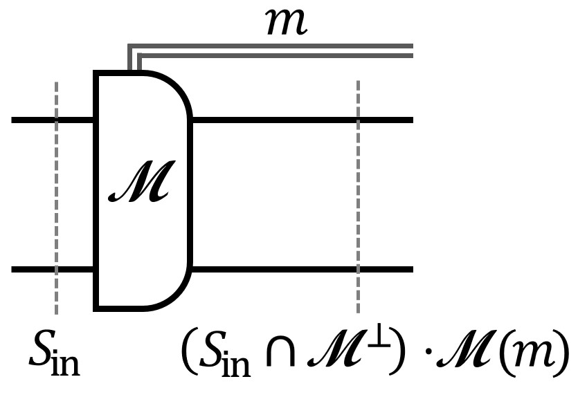 (b)
(b)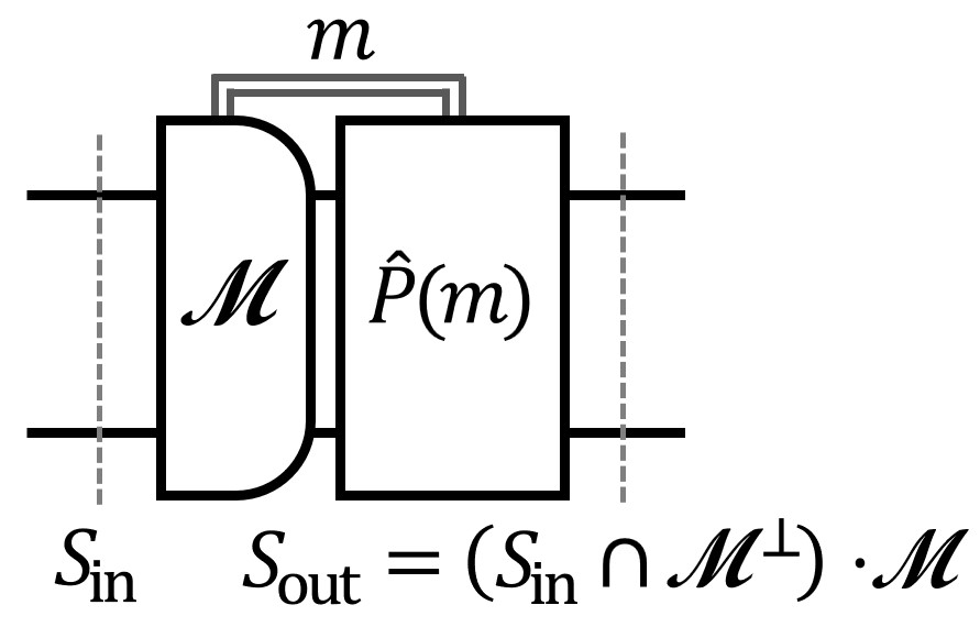 (c)
(c)
In what follows, we use the terminology and notation from Section II.3 on Pauli bases. The fix-ups are naturally defined in terms of a common symplectic basis which respect both and ; see Fig. 5(c). In this basis, the group is generated by the elements of , and , and is chosen such that for each element of or which has non-trivial outcome, its anticommuting partner from or is applied respectively.
From the common symplectic basis , the subset of generators and can each be multiplied by the stabilizer group to form a symplectic basis for the logical operators of the code , which we call . Similarly, we can use and to define a symplectic basis for the logical operators of .
The logical action of a phase-fixed code deformation step has a simple general form circuit as shown in Fig. 6. This general form circuit starts with a logical basis change of the code from to . Next, single-qubit measurements are applied (which measure all the logical operators of that have a representative in ). Lastly, a logical basis change of the code is applied from to .
An alternative approach to analyzing an elementary code deformation step is discussed in Ref. Vuillot et al. (2019).

IV.2 Stabilizer channels are code deformations
Here we begin by defining a code deformation sequence, which consists of a sequence of code deformation steps. We go on to explain that in fact all stabilizer channels can be considered as code deformation sequences.
We define a code deformation sequence as depicted in Fig. 7. Each of the steps has a Clifford unitary followed by a set of measurements of commuting Pauli operators which generate a group . We take to be the outcomes of a generating set for the group . We also find it convenient to include a conditional phase fix-up at the end of each step to ensure that the stabilizer group after each step is independent of the measurement outcomes.

We consider the channel’s logical action with respect to an input code with stabilizer group and an output code with stabilizer group (with their logical bases fixed by encoding circuits and ). The state after the th phase-fixed code deformation step has a stabilizer group containing , where for each and . We require for consistency between the channel and the specified output code that .
There are many ways to express a stabilizer circuit as an equivalent code deformation sequence . For example, one can split into a sequence of sub-circuits each of which has the same number of input and output qubits such that . Each sub-circuit is equivalent to a code deformation step (not necessarily phase fixed). This is because each sub-circuit is equivalent to a general form circuit Fig. 1 (with unitaries and destructive measurements), and the general form circuit with the same number of input and output qubits is equivalent to a code deformation step with and and appropriately chosen conditional Paulis. To get the channel in Fig. 7 it remains to adjust the conditional Paulis to ensure that every step is phase-fixed.
IV.3 Logical action of stabilizer channels
When a stabilizer channel has been expressed as a code deformation sequence, it is straight-forward to compute its logical action analytically. For any code deformation sequence, the logical action is equivalent to the simple general form circuit shown on the left of Fig. 8. Note that this is a restriction of the general form circuit shown in Fig. 1, having no random bit outcomes or conditional Pauli (by virtue of the phase fixing in the channel). The logical action of a code deformation sequence is fully specified by a -qubit Clifford unitary , an integer that specifies the number of independent logical Paulis measured by the channel, and a -qubit Clifford unitary . The logical outcome function identifies what the -bit logical outcome vector of the channel is given the channel outcome vector .

The general form circuit for the logical action of the channel makes it clear that any code deformation sequence simply measures out a set of commuting logical Pauli operators of the input code, and then re-encodes the remaining logical information in the output code in some basis. The inclusion of the zero-state ancilla in the general form allows for some logical degrees of freedom of the output code to be fixed.
As illustrated in Fig. 8, the Cliffords and which specify this general form can be found from more elementary logical basis change matrices. To define these basis changes, we introduce a sequence of symplectic Pauli bases , where for , we define as a common symplectic basis for and , and we take to be the Pauli basis specified by the input code encoding Clifford . To use Fig. 6 we need to specify with respect to which input and output symplectic bases each of the measurement rounds is analyzed. For round , we choose the input and output pair to be and . With the above choice of input and output symplectic bases, for all , is a logical basis change from to , and is a logical basis change of the code from to and is therefore equal to the identity. The Clifford in the general form on the left of Fig. 8 is then identified as a code basis conversion from (with encoding Clifford specified by ) to (with encoding Clifford specified by ).
Note that with these choices of bases, the logical action of is trivial with respect to the input code with logical operator basis and output code with logical operator basis .
IV.4 Fault effects of measurement outcome flips
Re-expressing the fault effect of measurement outcome flips in a circuit as fault configurations of Pauli operators with the same effect can be a useful technique. The main tool for this is the notion of an absolutely trivial fault configuration. Given a stabilizer channel and a sub-circuit of , a fault configuration within is absolutely trivial if the fault-free sub-circuit implements the same linear map as the sub-circuit with the fault configuration for all possible measurement outcomes of . Every absolutely trivial fault configuration is also a trivial fault configuration.
For example, consider a sub-circuit that measures a Pauli on some qubit, with a fault configuration of a Pauli right before the measurement. This is a simple example of a trivial fault configuration.
In Section VII, we use absolutely trivial fault configurations to analyze the fault-tolerant properties of code deformation rounds. Specifically, consider a code deformation round that consists of measuring a commuting set of Pauli operators . Let be a Pauli operator that anti-commutes with and commutes with the rest of the measured Pauli operators. The fault configuration that consists of (1) a Pauli before measuring , (2) an outcome flip of , and (3) a Pauli after measuring , is an absolutely trivial fault configuration. This allows us to analyze the outcome flip of in terms of an equivalent fault configuration consisting of Pauli operators.
V Combining stabilizer channels
The goal of this section is to establish necessary conditions on a set of stabilizer channels, so that a stabilizer channel composed from the set of stabilizer channels has fault distance . The key technical condition we require of the stabilizer channels is that they have a specific time-locality property. In what follows, we provide a rigorous definition of this property and show that for a stabilizer channel which satisfies it, the simple fault configurations must be contiguous in time. This will allow us to localize any undetectable fault configuration in a composed stabilizer channel to a pair of consecutive stabilizer channels in the composition.
Definition V.1 (Time-local stabilizer channels).
Consider a stabilizer channel with elementary fault set . Let be a partition of the elementary fault set into disjoint subsets. We say that the stabilizer channel with checks is time-local with respect to this elementary fault set partition if the check set can be partitioned as such that: (a) checks in depend only on the input code syndrome of the input error and elementary faults in , and can be calculated from checks in when there are no faults, (b) checks in depend only on elementary faults in for (c) depends only on the checks and elementary faults from .
Let us next show that simple fault configurations must be contiguous in time in a time-local stabilizer channel. Consider a simple fault configuration and suppose that it is a subset of for , and that is non-empty for all . We show that for each it must be that , that is the fault configuration is contiguous in time. Suppose that this is not the case for some , then fault configurations and must both both be undetectable, which is a contradiction to being simple.
The composition of two time-local stabilizer channels is again a time-local stabilizer channel. To see this, consider stabilizer channels and that are time-local with respect to partitions of the elementary fault sets and , and of the check bases and . We require that , and consider them with respect to the same symplectic Pauli basis. We seek to show that the composed channel is time-local with respect to the partition of elementary fault set . We must also specify the set of checks and their partition for the composed channel . Recall that the checks in depend on the input code syndrome of the input error and faults in . Also note that is a function of faults in and checks in . For this reason can be expressed as a function of checks in and faults in . We can modify into by combining it with checks in , such that depends on . The check basis partition satisfies the properties needed to establish the time-locality of .
Note that when the time-locality condition becomes very simple. It requires that the input syndrome can be inferred from the checks when no faults occur in the channel. Indeed, if this is the case we can re-express the output syndrome as a linear function of the fault vector and checks.
For the rest of this section, let us consider the case of uniform weights. In this case, a simple fault configuration of weight in a time-local stabilizer channel can span at most consecutive elements of the partition for some . Otherwise its weight would be greater than . This observation is crucial to establish the conditions under which stabilizer channel composition is distance preserving.
Theorem V.2.
Let , , be a sequence of compatible 222 We say that the stabilizer channels in a sequence are compatible if the output stabilizer code of each channel in the sequence matches the input stabilizer code of the next channel in the sequence. time-local stabilizer channels with unit-weight faults. Suppose that compositions , are stabilizer channels with fault distance at least and the partition with respect to which is time local is at least of size , then stabilizer channel has fault distance at least .
Proof.
We prove the result by contradiction. Suppose that the stabilizer channel composition has a non-trivial undetectable fault configuration of weight . Without loss of generality, we choose to be simple. Note that that stabilizer channel composition is time-local stabilizer channel with respect to the partition of the elementary fault set . Fault configuration must be supported on at most contiguous time partitions, and , therefore must be supported on either (A) or (B) .
Next we show that the fault configuration corresponds to a simple non-trivial fault configuration of either in case (A), or of in case (B). In both cases, this forms a contradiction since has weight but both and have fault distance at least . In case (A), the output syndrome of is zero because it is equal to the input syndrome of in the stabilizer channel composition and time locality of implies that the only way for the output syndrome of to be zero in the absence of faults in is for the input syndrome to be zero. Similarly, the only way can have non-trivial logical effect with respect to is if it has non-trivial logical effect with respect to . In case (B), the input syndrome of is zero because there are no faults in the part of the composition and there are no logical errors caused by . The only way for to be a non-trivial undetectable fault configuration is if it is a non-trivial undetectable fault configuration in , which completes the proof. ∎

We conclude with a set of conditions on a set of stabilizer channels that ensure that their compositions have fault distance . For simplicity, we consider the setting of stabilizer channels with the same number of input and output logical qubits, acting on one or two logical qubits encoded in the same code, although it is straightforward to generalize these conditions to broader settings. Consider two finite sets of time-local stabilizer channels and . Stabilizer channels in are required to be time-local with fault-set partition of at least size and act on one logical qubit. Additionally, we require that for any pair of one-qubit stabilizer channels from , from compositions , have fault distance . Similarly, we require that for any two-qubit stabilizer channel from , and one-qubit stabilizer channels from compositions , have fault distance . Theorem V.2 implies that any composition of above stabilizer channels that interleaves short and long stabilizer channels is a stabilizer channel of fault distance at least , as illustrated by Figure 9. Above argument can be extended to the stabilizer channels that have different number of input and output logical qubits, as well as the stabilizer channel using multiple different codes for the logical qubits.
Note that the tools of this section can be used to analyze arbitrary arbitrary compositions of channels from a set of one-time-local distance- channels, at the expense of analyzing all possible compositions of such channels.
VI Algorithms for fault distance and hook faults
Given a stabilizer channel and a local stochastic Pauli noise model with fault set , one can, in principle, calculate the fault distance directly by enumerating faults to find the lowest weight non-trivial fault. However, the time complexity of such a brute-force approach will be exponential in the number of elementary faults in . Sometimes it is possible to express the channel check matrix as a graph in which the undetectable faults correspond to cycles, allowing efficient calculation of the fault distance. In Section VI.2 we review how this so-called syndrome graph can arise for a stabilizer channel, and point out existing efficient algorithms developed in the 1960s-1980s (which we believe are not widely known in the quantum computing community) that can be used to put a syndrome matrix into graph form. In Section VI.3 we review existing algorithms to efficiently compute the fault distance given a syndrome graph. In Section VI.4 we provide a new simple algorithm for identifying hazardous hook faults. In Section VI.5 we review a number of approaches that can be used to find or bound the channel distance even when it is not possible to express the channel check matrix as a graph. In the same section, we also point out some new connections between computing channel check distance and binary matroids.
VI.1 Channel check and logical effect matrices
There are a number of approaches to efficiently compute complete set of channel checks, channel check matrix and logical effect matrix for an arbitrary stabilizer circuit 333It it common to explicitly specify checks for a fault-tolerant circuit, here we review approaches that do not require that. One approach is based on space-time and outcome code of a stabilizer circuit Delfosse and Paetznick (2023a, b). The algorithms for a general form of a stabilizer circuit and the circuit’s logical action from Kliuchnikov et al. (2023) can also be used for this purpose.
VI.2 Graph-like channel check matrices
Consider a channel which has a channel check matrix , expressed over the check basis . We say the channel check matrix is graph-like if there exists a choice of check basis with the same span as such that each column of has Hamming weight one or two. The syndrome graph is then constructed from as follows. A vertex is included in the vertex set for each row of , along with an additional boundary vertex. For each weight-2 column of , an edge connecting the two vertices corresponding to that row’s support is included in the edge set . For each weight-1 column of , an edge connecting the boundary vertex to the vertex corresponding to that row’s support is included in . By construction, every edge in corresponds to an elementary fault in and there is a logical effect associated with every edge , and the edge has a weight given by as defined in Section III.1.
To relate undetectable faults to cycles in the graph we recall the definition of the cycle space of a graph. We call a subset of edges a cycle if the sub-graph has even-degree vertices. With every set of edges we associate an indicator vector . As the symmetric difference of two cycles is again a cycle, vectors for which is a cycle form a vector space over the cycle space of the graph Diestel (2017). Importantly, there exist efficient algorithms that can determine if is graph-like and construct the corresponding decoding graph Fujishige (1980); Bixby and Cunningham (1980); Truemper (2014); Walter and Truemper (2012).
VI.3 Graph-based fault distance algorithms
There are a number of existing approaches that can be used to compute the fault-distance given a decoding graph . One approach is to modify Dijkstra’s algorithm, which is an approach alluded to in and implemented in Gidney (2021).
A second approach is to generalize the algorithm for finding minimal weight logical operators of CSS surface codes from Breuckmann et al. (2017) (attributed therein to a communication with Sergei Bravyi). In this approach, one uses the fact that each row of the logical effect matrix defines a set of edges of the decoding graph . A minimal weight non-trivial fault then corresponds to a cycle that has odd overlap with at least one of the s. Finding a minimal weight cycle that has an odd overlap with a subset of edges is an example of the shortest odd cycle problem de Pina (1995). A key technique used to solve such problems is to reduce the shortest odd cycle problem in a graph to shortest path problems in a related graph with twice the number of vertices and edges, constructed based on de Pina (1995). For completeness, we provide Algorithm 2 for shortest odd cycle problem in Appendix A. Notably, this approach generalizes slightly beyond graph-like matrices, as discussed in VI.5.
The asymptotic runtime of both approaches to computing the fault-distance given a decoding graph is the same. For being the number of rows of the logical effect matrix, the runtime is .
If something is known about the syndrome graph and its non-trivial cycles, one can often speed up both algorithm. For example, a common scenario for topological codes is that the syndrome graph is a cellulation of an underlying smooth topological manifold, in which case the cycles corresponding to logical fault configurations correspond to non-contractible loops, while cycles with trivial action on the channel are contractible loops. In some such cases, one can be sure that any non-trivial cycle will pass through the boundary vertex, and as such we can considerably reduce the run time of the algorithm by only considering the cycles that pass through the vertex. If the upper-bound on the weight of minimal cycles is known, one can also speed-up the algorithms. We provide further details on how to speed-up the second approach in Appendix A.
VI.4 Graph-based hook fault algorithm
Here we present a simple algorithm for finding hazardous hook faults. The algorithm requires the channel check matrix of to be graph-like and requires faults to have positive weights. In this scenario, hazardous hooks can be identified by finding a minimal weight cycle in the syndrome graph with modified weights. Indeed, to check if a given hook fault is hazardous we need to know if a minimal weight non-trivial fault configuration passes through it. However there could be many such minimal configurations and we don’t know which our fault distance algorithm will discover. We can overcome this however by reducing the weight of the hook fault by a small amount where , to ensures that if the hook fault is hazardous, it will be contained in any minimum weight paths that are now found. We use this to form Algorithm 1.
VI.5 Beyond graph-like channel check matrices
Here we discuss a number of cases where the channel check matrix is not graph-like, but where we can use additional structure to calculate or at least bound the fault distance of the channel.
Upper bounding the fault distance.— When the channel check matrix is not graph-like, an upper bound on the fault distance can be found by finding any non-trivial undetectable fault configuration. One way to achieve this is to use a BP-OSD decoding approach as pointed out in Ref. Panteleev and Kalachev (2021). Here we propose another method to form upper bounds using a graph that can be constructed, which we call the restricted syndrome graph. In what follows, we explain how this works. First we choose a check basis (the restricted syndrome graph can depend on this choice), and then build the graph by adding edges as normal for those columns which have Hamming weight one or two (it can beneficial to choose a basis that maximizes the number of such columns). Then finding the fault distance from this graph using the algorithm in Section VI.3 will provide an upper bound for the fault distance of the channel. This is because we will have found the smallest non-trivial fault given a restricted elementary fault set, which will still be non-trivial for the full fault set but may not be minimal.
Lower bounding the fault distance.— We can also lower bound the fault distance by constructing a different graph, which we call the reduced syndrome graph . In what follows, we explain how this works. We start by building as before, but now we will also include edges for the remaining columns of the channel check matrix as follows. Suppose that is the Hamming weight of one of the remaining columns, and let be the weight of the fault that column corresponds to. We add a new vertex to the graph (similar to the boundary vertex), and add new edges to the graph, with each edge having weight and connecting to the new vertex. These edges connect pairs of the vertices in the fault (and connect one vertex to the boundary vertex if is odd). We assign all of the residual error from the elementary fault to one of these new edges, and set the other residual errors to be trivial. This is done for all remaining columns to produce . Suppose that the true fault distance of the channel is , and let be the fault distance of (which can be obtained by running the algorithm in Section VI.3 on ). The key here is to note that the minimum weight non-trivial faults for the true channel can all be considered as the minimum-weight one by the graph algorithm for , and it is proposed then it will have the correct weight. If another fault is proposed which contains just some of the new edges without the full fault, then it must have lower weight than the true lowest weight non trivial logical fault. Hence we obtain a lower bound.
Checking if a check matrix is ‘almost’ graph-like is an interesting open question. Let us consider a simple special case of this problem. Given a set of linearly independent channel checks of size , find a set of linearly-independent checks from the span of such than the corresponding channel check matrix is graph-like. This problem is closely related to the problem of recognising even-cycle binary matroids for which an efficient algorithm has recently been discovered Heo and Guenin (2020); Guenin and Heo (2023).
If the fault set ‘separates’ into fault-sets with known fault distances .— In many stabilizer channels of interest, the channel check matrix is not graph-like, but we can split the decoding problem into independent parts that are graph-like. This happens for example due to errors in surface codes, which result in four rather than two checks being flipped for the standard choice of checks in the surface code. We can treat the as being composed of an and a , and handling and errors separately. We now formalize this scenario more abstractly, using an approach similar to that described in Refs. Delfosse et al. (2023); Gidney (2021). We require the following from the fault set, channel check and logical effect matrices:
-
1.
The fault set separates into disjoint fault sets , so that fault distance with respect to each of the first fault sets alone is at least .
-
2.
For the first fault sets the spans of the columns of the check matrices with respect to are linearly independent subspaces.
-
3.
Each elementary fault from triggers the same checks and has the same logical effect as a sum of elementary faults from the first fault sets. The sum includes at most one elementary fault from each .
If the above properties hold, the fault distance is at least . This is because any undetectable fault of weight corresponds to an undetectable fault of weight at most with respect to each of . Moreover, a non-trivial fault of weight must correspond to a non-trivial fault of weight at most with respect to one of .
If the channel check matrix is a regular matroid. It is possible to efficiently find the fault distance for a more general class of check matrices, namely the matrices that correspond to binary regular matroids Truemper (2014). The matrices that are graph-like are a proper subset of those which correspond to binary regular matroids. There exist efficient algorithms and their C++ implementations that check if a given matrix corresponds to a regular matroid Truemper (2014); Walter and Truemper (2012). An efficient algorithm for solving an analog to an odd cycle problem in regular binary matroids is presented in de Pina (1995). We are not aware of any practical examples where channel check matrix is a regular matroid but not graph-like. Identifying such examples, as well as decoding algorithms for this class of check matrices is an open question. Another promising case is for channel check matrices related to perturbed graphic matroids, which have an efficient algorithm for a shortest cycle problem Geelen and Kapadia (2018). It is an open problem to find an efficient algorithm shortest odd cycle in perturbed graphic matroids.
VII Examples with surface codes
In this section we illustrate some of the main concepts discussed in earlier sections by working through two stabilizer channel design examples. We use the following common strategy to design circuit implementations of a given logical operation with fault distance :
-
1.
Code-deformation sequence.— First find a sequence of codes and which have at least code distance (for all logical Pauli operators which are not measured out by the channel). The sequence should be chosen such that the first and last rounds match the input and output codes, and the logical operators evolve as required by the logical operation as described in Section IV.3.
-
2.
Phenomenological implementation.— Then, one specifies a phenomenological version of the channel in terms of generator measurements for the code sequence. Under a simple phenomenological noise model, modifications are made to ensure a fault distance of the channel is calculated as in Section VI such as repeating some rounds, or adding intermediate codes to the code deformation sequence.
-
3.
Circuit implementation.— Lastly, one specifies an explicit stabilizer circuit implementation of the channel in terms of allowed instructions. This circuit is built from extraction circuits that measure the generators of the phenomenological implementation, and as such there is a natural restriction of the circuit noise to the phenomenological noise as in Section III.4. In this section, we will refer to both hazardous and brazen hook faults collectively as bad hook faults. To achieve fault distance , we ensure that the extraction circuits are valid, i.e. they act correctly when performed together in the overall circuit and also seek to eliminate bad hook faults. It may be necessary to modify the Phenomenological implementation by increasing round repetitions etc.
In Section VII.1 we fix the setting for our surface code examples. In Section VII.2 we design a stabilizer channel to non-destructively measure the logical operator of a pair of surface codes. This is a standard example, but acts as a warm-up to clarify our broad approach to design fault-tolerant stabilizer channels. Then in Section VII.3, Section VII.4 and Section VII.5 we design a stabilizer channel to fault-tolerantly implement the logical Hadamard on a surface code patch at circuit level. In this second example we see that a number of intricacies arise which must be handled to achieve a fault distance , some of which we believe have not been noted in prior literature. This adds to the collection of intricacies arising in fault-tolerant circuit design Gidney (2023a); Chamberland and Campbell (2022); Gidney and Bacon (2023); McEwen et al. (2023); Gidney (2023b); Geher et al. (2023).
VII.1 Surface code stabilizer channels
(a)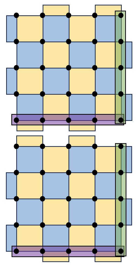 (b)
(b)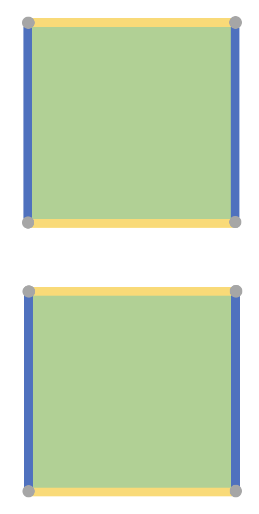
By the term “surface code”, we refer to a broad class of quantum error correcting codes defined on qubits embedded in two-dimensional surfaces with a pattern of local stabilizer generators tiling the surface. There are many variants due to the range of surfaces that can be chosen, a choice of how the qubits are embedded in the surface, and some local freedom in the tiling both in the bulk, but also along the boundaries. Among the most familiar surface codes are the family of square-patch surface codes depicted in Fig. 10, which we will call the standard patch. In this section, we are interested in stabilizer channels that implement logical operations on surface codes. We will assume the following throughout:
-
•
Qubit layout.— Physical qubits can be placed on the sites of two lattices on : the data lattice consisting of integer points , and the ancilla lattice consisting of half-integer points . In most figures we just show the data lattice.
-
•
Input and output codes.— The input and output codes for the channels we consider are a pair of surface code patches as shown in Fig. 10(a). All of our figures will be shown for the case but generalize to arbitrary odd integer distance .
-
•
Instantaneous stabilizer codes.— When viewed as a code deformation channel, instantaneous stabilizer codes are surface code patches with each check being weight-four or weight-two restrictions of an alternating checkerboard pattern.
-
•
Phenomenological instruction set.— We allow joint-Pauli preparations and measurements supported on sets of up to four data qubits contained within a unit square. We also allow for the simultaneous shift of all qubits in a region by a uniform displacement vector, even if the shifted region overlaps with the original region.
-
•
Circuit instruction set.— We allow the circuit operations and faults specified in Section III.1, with two-qubit Clifford unitaries between nearest-neighbor data-ancilla pairs. We further assume that any generators measured by circuits are done so using a single ancilla qubit and a CNOT circuit as shown in Fig. 11 (and discuss hook faults in the same figure).
-
•
Fix-ups.— In this section we follow the convention that stabilizer channels are circuits with all conditional Paulis at the end as in Fig. 2.
-
•
Channel checks.— We construct the check set in the phenomenological implementation (and use the same checks for the circuit implementation) in such a way that the fault sets separate into graph-like decoding matrices as described in Section VI.5. For each Pauli measured in a phenomenological round we consider both the previous and the next round. If is a product of Pauli operators measured in the previous round we add the corresponding check. If is a product of Pauli operators measured in the next round we add the corresponding check. We do not add the same check to the set of checks twice. When constructing the checks for the first and last rounds respectively, we follow the same principle but use the input syndrome in place of a round before the first, and the pre-phase-fixed output syndrome in place of a round after the last 444Recall that we follow the convention where the conditional Paulis are placed between the last round and the output syndrome of a stabilizer channel (as in Fig. 2). To obtain the pre-phase-fixed output syndrome, we commute the output syndrome past the conditional Paulis to find the values they would have immediately after the final round..
-
•
Noise.— We assume the standard circuit noise model in Section III.1, with unit weights for faults. The fault set for the phenomenological noise is bit-flips of measurement outcomes and i.i.d. Pauli noise on qubits between rounds. Note that these phenomenological faults can always be considered as a strict subset of the faults of the circuit noise model in accordance with the hook fault definitions in Section III.4.
(a)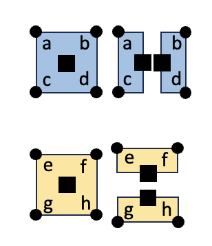 (b)
(b)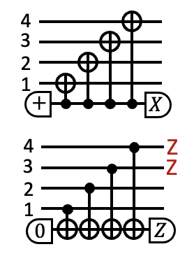 (c)
(c)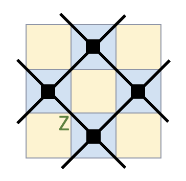 (d)
(d)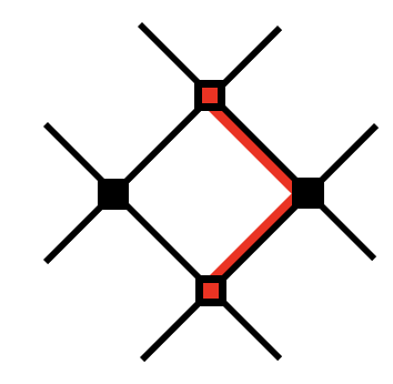 (e)
(e)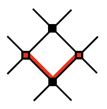 (f)
(f)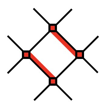 (g)
(g)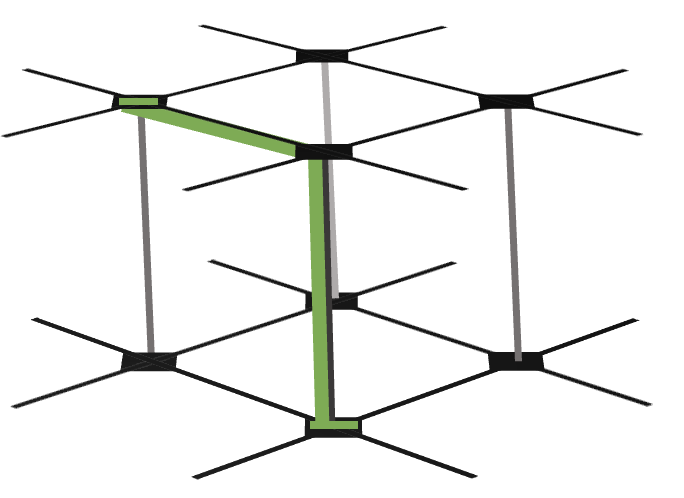 (h)
(h)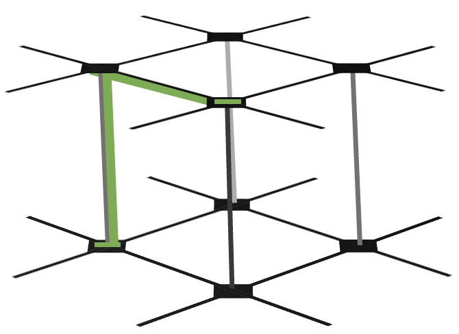
VII.2 XX measurement
In this warm-up example we apply some of the techniques we have introduced to carry out the three-step design flow to construct a fault-tolerant implementation of the logical measurement of a pair of surface code patches. In this example, we reproduce the well-known lattice-surgery implementation of this operation.
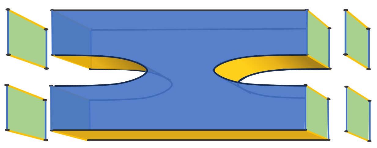
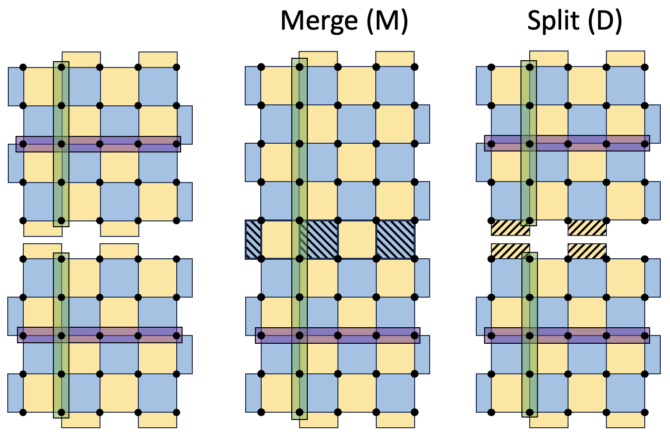
Code deformation sequence.— We begin with a topological viewpoint of how this logical gate can be applied as shown in Fig. 12 (an understanding of the topological viewpoint of surface codes will not be necessary to understand the results in this section, but we include a brief overview in Appendix B for completeness). To form an explicit code-deformation sequence from this topological picture, we consider three time-slices which correspond to the sequence of surface codes shown in Fig. 13. In this code deformation sequence, an input pair of surface code patches (with stabilizer group ) are first merged together into a single surface code patch (with stabilizer group ), and then split once more. Note that each code in this sequence has code distance .
The logical action of this code deformation sequence is straight forward to calculate using the approach in Section IV.3. The input and output code basis are the standard choices of logical and for both patches as illustrated in Fig. 14.

Phenomenological implementation.— The phenomenological channel consists of the following rounds:
-
1.
rounds: measure the generators of .
-
2.
round: measure the generators of .
It is well-known that the channel check matrix in this example has the property described in Section VI.5 whereby it separates into two graph-like matrices. Specifically, this occurs when we separate faults into (i) Paulis and -check flips producing the decoding graph , and (ii) Paulis and -check flips, forming the decoding graph as shown in Fig. 15. Each of the remaining faults are Paulis described as the combination of precisely one Pauli fault in and one Pauli fault in .
(a)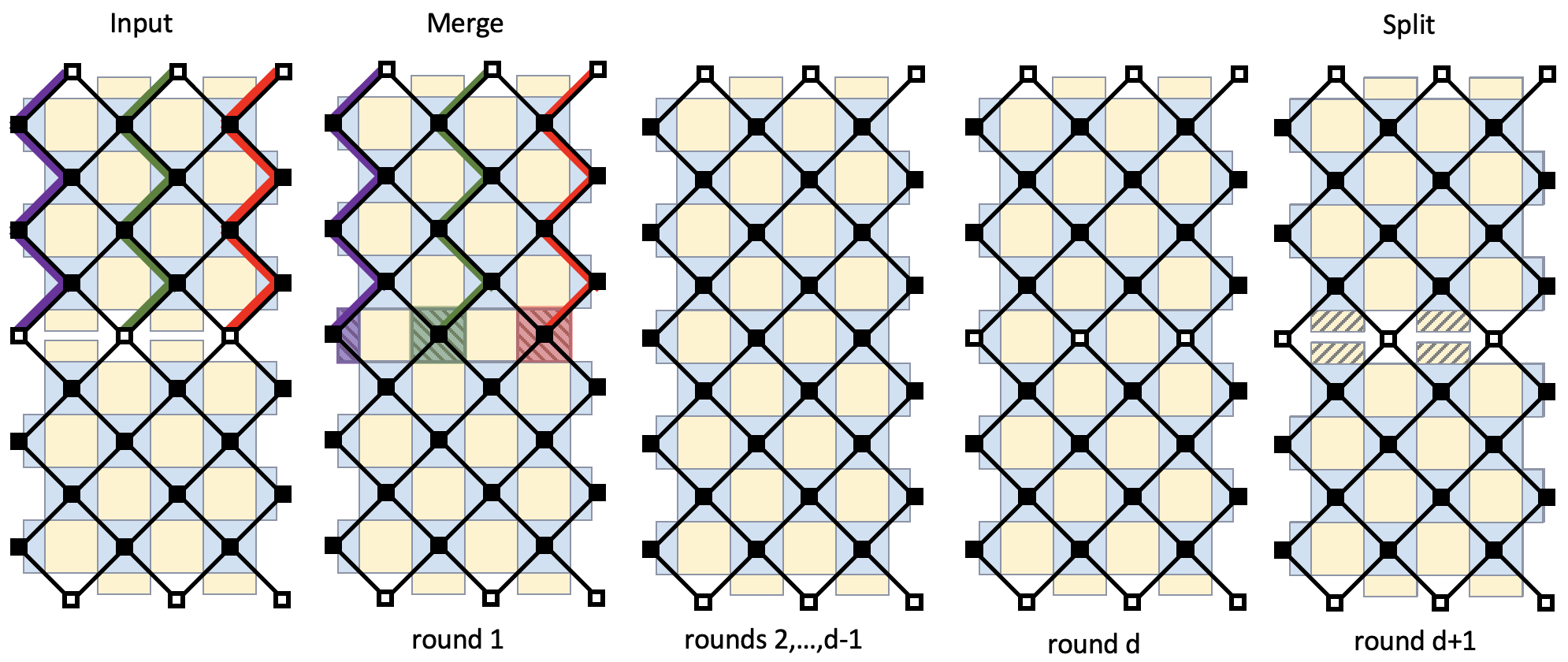 (b)
(b)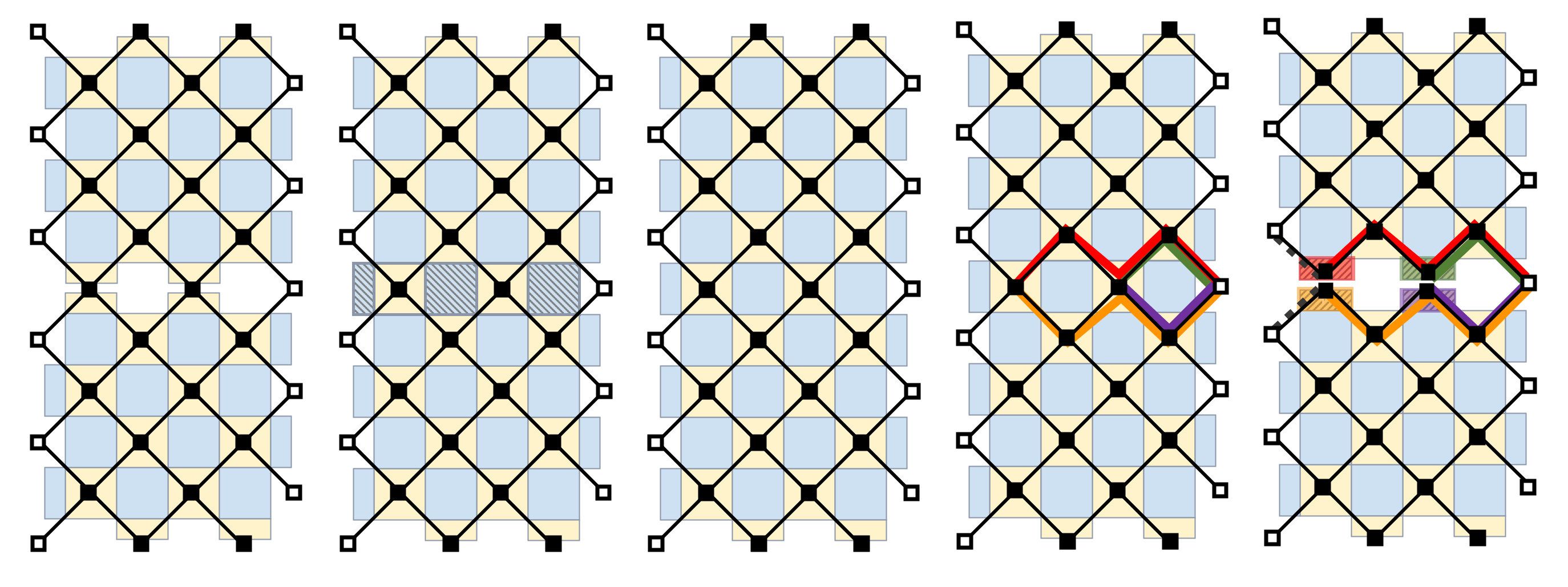
To see why the first code deformation step is repeated times to form the phenomenological implementation of the channel, it is important to understand the lowest-weight non-trivial logical fault configurations of this phenomenological channel. Clearly, the space-like logical operators of the instantaneous stabilizer groups (indicated on Fig. 13) can result in logical faults. Simply by choosing the code patches to be distance as shown ensures those logical faults are all of size at least . There are time-like logical faults too: a repeated outcome flip of any one of the shaded checks in of Fig. 13 corresponds to a string of vertical edges in Fig. 13 connecting the boundary vertex to itself and will not be seen by any channel check and will result in the outcome from being flipped. These time-like logical faults require us to use repeated rounds – if fewer repetitions were made then the undetectable logical outcome flip could occur with fewer than faults.
Looking at the decoding graphs and in Fig. 15, one may wonder why the high-weight colored faults that arise due to flips of the random outcomes do not result in a reduction of the distance. For , the merge step introduces vertical weight-() strings (red, green, purple) - these lie along minimum-weight logical operators of the stabilizer code after that time step. However, these minimum-weight logical operators have weight , and as such these faults do not reduce the distance below . The reason that the flips of the shaded measurement outcomes in round of Fig. 15 do not reduce the fault distance of is more subtle. Take for example the weight-4 undetectable fault configuration formed from the red and orange faults and the two dashed edges in Fig. 13. A careful analysis of this fault configuration shows it corresponds to the application of a stabilizer immediately before round , and then the application of a logical Pauli operator immediately before round . However, this logical operator has trivial logical action as defined in Section III.2, since the logical operator is stabilized by the output state (given that the channel measures this operator).
Circuit implementation.— The circuit-level implementation of the channel requires additional ancilla qubits as shown in Fig. 16. The channel consists of the same rounds as the phenomenological channel, but with the weight-two and weight-four Pauli measurements replaced by extraction circuits as described in Fig. 11. As noted earlier in this section, we (i) require that these circuits are valid, and (ii) avoid bad hook faults.
To ensure the circuits are valid amounts to careful checks on the ordering of any interleaved CNOTs such that the Pauli measurements in the code deformation sequence are correctly implemented in the absence of faults. To avoid bad hook faults one could in principle check that each circuit fault individually. However, this assumes we already have a circuit in mind to test. It can instead be useful to motivate good candidate circuits by ensuring they avoid some known patterns that result in bad hooks. One such pattern is to ensure that time-like hook faults of the type shown in Fig. 11 do not have large overlap with the minimum-weight logical operators of the instantaneous stabilizer groups of the channel as discussed in Fig. 16. As is already known Chamberland and Campbell (2022), we find that the standard extraction circuits for surface codes avoid these known patterns.
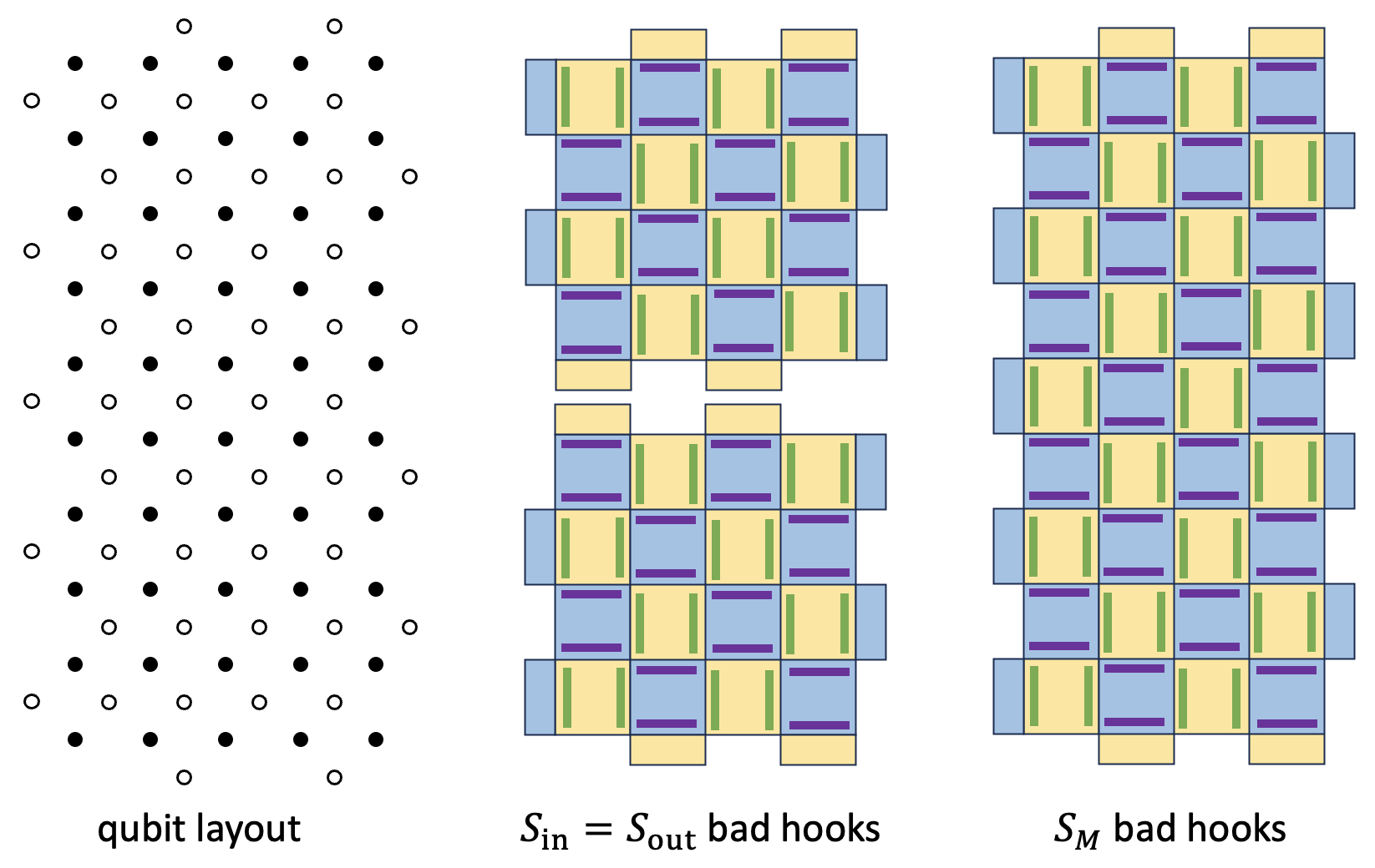
The checks are the same as for the phenomenological channel. Given these choices, the resulting channel check matrix once more separates into graph-like parts for the subset of faults that only flip -checks, and for the subset of faults that only flip -checks, with all other faults decomposing into these types. The fault distance of this circuit implementation of the channel is .
VII.3 Hadamard: deformation sequence
We begin our design of a fault-tolerant implementation of a logical Hadmard gate by proposing a code deformation sequence based on a topological viewpoint of this gate, which is very natural as shown in Fig. 17. The code is rotated, such that the boundaries where the logical and string operators terminate are swapped, and then a transverse Hadamard is applied to the data qubits which exchanges all and stabilizers and logical operators. This leaves the code oriented as it was initially, but with the logical operator having been mapped to the logical operator and vice-versa, as is required for the logical Hadamard.
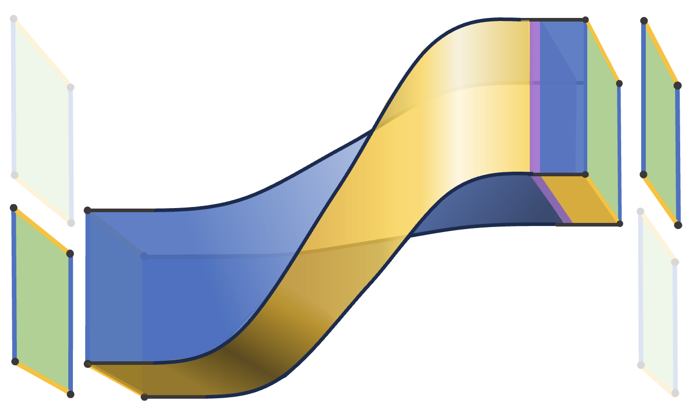
In Fig. 18 we give a code deformation sequence which implements the logical Hadamard, or more specifically, the logical Hadamard along with a patch move. This can be considered an explicit implementation of the topological viewpoint of the channel in Fig. 17. We note that if one requires the patch of the output to be in the same location as the input patch, one can use a logical move operation. We focus on the ”Hadamard plus move” here because it has a lower time cost by avoiding the patch move and therefore may be beneficial in practice.

(a)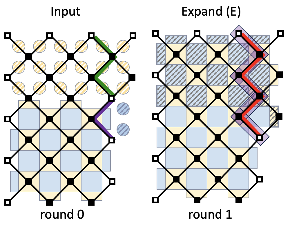 (b)
(b)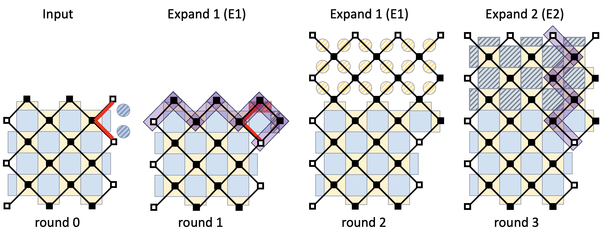
VII.4 Hadamard: phenomenological implementation
When we build the phenomenological implementation, we might at first hope that, like in our logical measurement example, we simply need to ensure that some of the codes formed in the code deformation sequence we found in Section VII.3 need to be repeated in order to achieve a fault distance . However, this does not work — as is discussed in Fig. 19, the steps of the code deformation sequence introduce a weight undetectable non-trivial fault configuration. This can be avoided by including an additional code deformation step, by splitting the expand step into two sub-steps as shown in the same figure.
The phenomenological channel consists of the following rounds:
-
1.
rounds: measure the generators of .
-
2.
rounds: measure the generators of .
-
3.
rounds: measure the generators of .
-
4.
round: measure the generators of .
-
5.
round: apply transverse Hadamard to data qubits.
-
6.
rounds: shift data qubits distance to final position. This can be achieved by a sequence of shifts using qubits in the ancilla lattice (this is the same approach as we use in the circuit implementation of the channel, and we provide more explicit details for that in Fig. 22.
VII.5 Hadamard: circuit implementation
As we saw in the logical measurement example, the choice of circuits to implement the generator measurements is very important. In Fig. 20 we consider a number of the surface code patches in isolation and analyze which space-like hook faults would be bad for each check in the various patches, which constrains the circuits that can be used to perform generator extraction.
(a)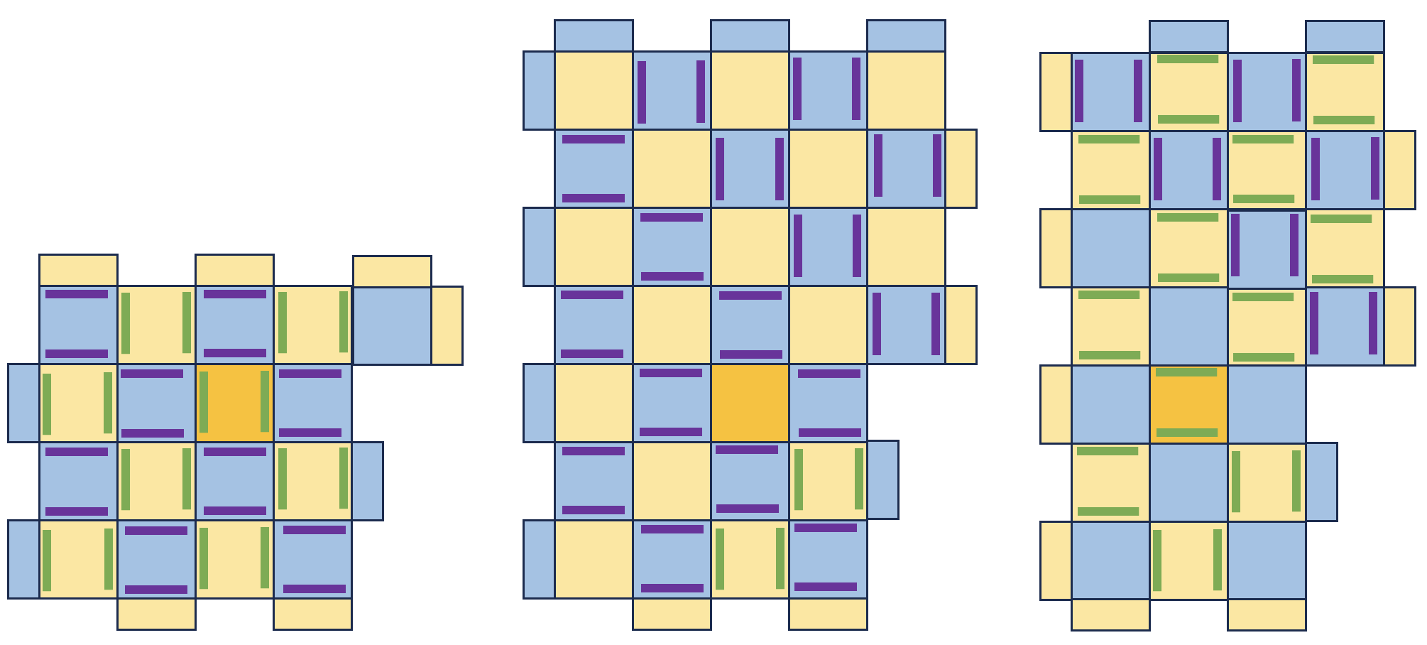 (b)
(b)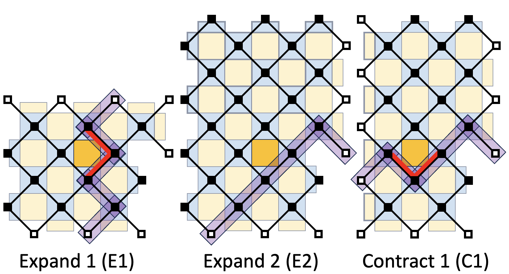
From Fig. 20, it is clear that although some generators appear in multiple code patches (such as that highlighted in yellow), the circuit requirements can depend on the patch. However, choosing a circuit that avoids bad hook faults for each stabilizer code independently is not sufficient to achieve the fault distance of the channel. One also needs to consider the effects of hook errors with respect to logical faults that span a range of times.
Many minimum-weight logical fault configurations in the circuit implementation can be understood by first considering space-like logical operators that are present in the stabilizer codes corresponding to time-slices of the phenomenological implementation. As we saw in Fig. 11, circuit faults can introduce diagonal space-time edges to the decoding graph, which can allow the space-like logical fault configurations to be deformed in the time direction without increasing the weight of the fault as in Fig. 21.
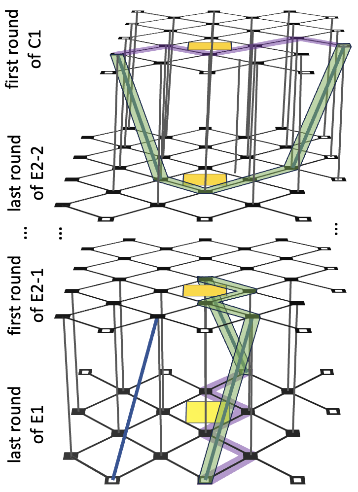
To avoid bad hook faults which can arise due to diagonal edges in the decoding graph, we can ensure that the space-like hook errors pointed out for each time-slice of the phenomenological decoding graph in Fig. 20 also don’t occur in any of the rounds before or after that round. This leads us to split stage E2 into two substages E2-1 and E2-2, each consisting of rounds, with different syndrome extraction circuits. We take a more abstract viewpoint of this property in Fig. 22(a), which also shows that C1 must be split into two substages.
The precise number of rounds for each stage in needed in Fig. 22(a) depends on the precise details of the circuits used – for example which diagonal edges are present in the decoding graph. In Fig. 22(b) we provide explicit circuit families, and use the distance algorithm to show that the specified numbers of rounds is sufficient to achieve full distance for . We observe that about rounds are sufficient for E2-1 for example, which can be understood by inspecting the diagonal space-time edge structure of the circuits in E2-1, and noting that only half of them point in the -direction, such that after rounds of E2-1, there is no-longer any need to avoid hook faults in the -direction.
The circuit implementation of the logical Hadamard then consists of the following rounds:
-
1.
rounds: measure the generators of with E1 circuits.
-
2.
rounds: measure the generators of with E2-1 circuits.
-
3.
rounds: measure the generators of with E2-2 circuits.
-
4.
rounds: measure the generators of with C1-1 circuits.
-
5.
rounds: measure the generators of with C1-2 circuits.
-
6.
round: measure the generators of with C2 circuits.
-
7.
round: apply transverse Hadamard to data qubits.
-
8.
rounds: translate the patch a distance to final position.
Note that the total number of time steps in the circuit implementation is more than the phenomenological implementation, essentially because C1 has been broken into C1-1 and C1-2 and each require rounds, but also some syndrome extraction circuits need 5 rather than 4 CNOT time steps.
(a)
(b)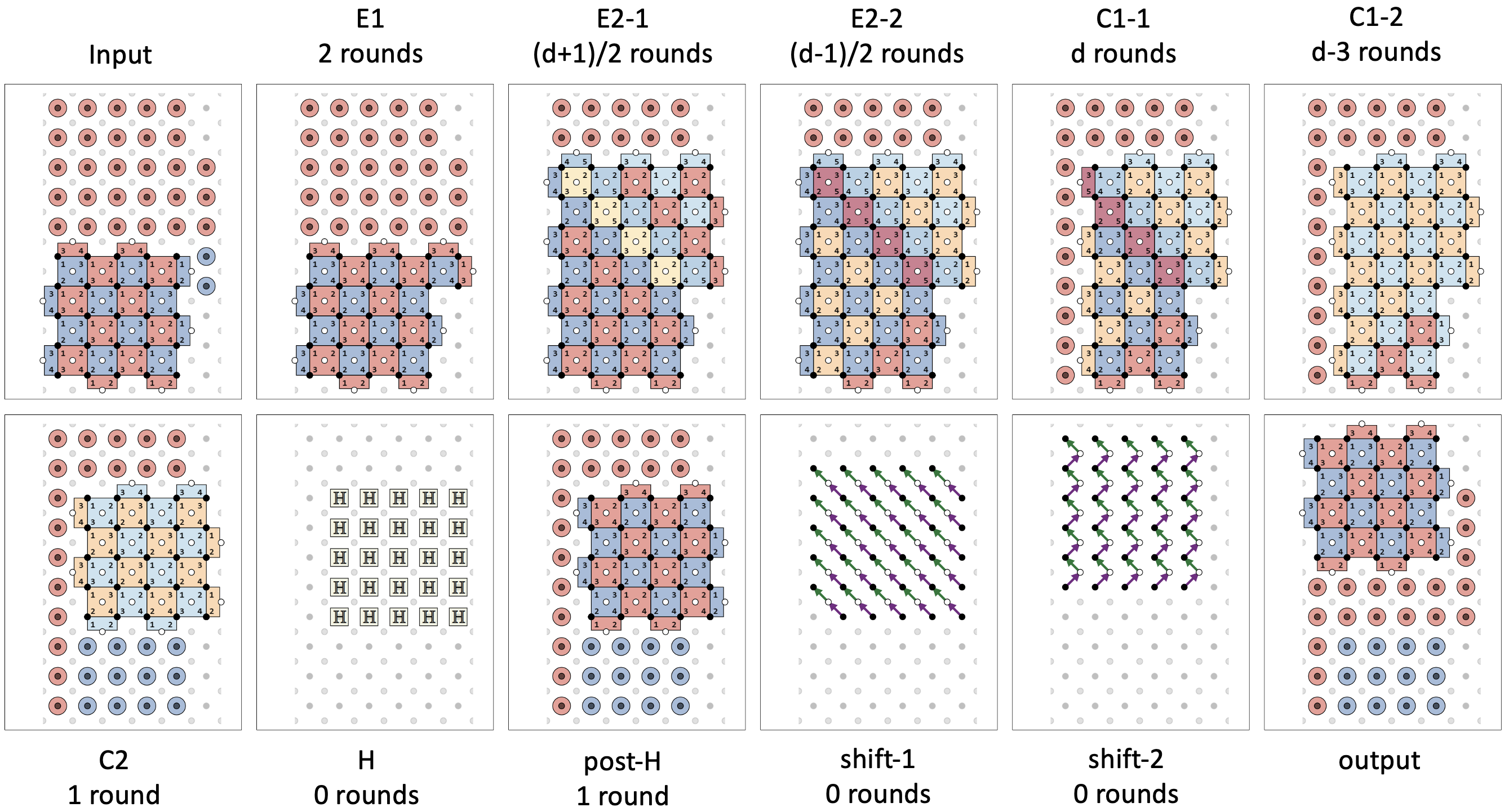
Relation to other work.— Prior to the recent work in Ref. Gehér et al. (2023), the known approaches to implement the logical Hadamard with surface codes can be viewed as variants of that originally proposed in Ref. Horsman et al. (2012) in which a transverse Hadamard is applied to the data qubits of a surface code patch, and the patch is rotated by first expanding the patch and then shrinking it. It is assumed in Ref. Horsman et al. (2012) that at the phenomenological-level, the expansion and shrink can both be accomplished by a single step followed by rounds of stabilizer measurements. We find however that this results in the fault distance dropping below the code distance, and we propose a modified full-distance version of this phenomenological implementation that includes a few additional patch deformation steps to avoid this problem. This problem is also avoided by the phenomenological implementations of Ref. Vuillot et al. (2019) and Ref. Fowler and Gidney (2018), but with different space and time cost tradeoffs. To extend the full-distance phenomenological implementation to form a full-distance circuit implementation with single-ancilla measurement extraction circuits, we find that the circuits must vary both spatially and temporally as the patch is deformed, and yet more idling steps must be added.
Recent Ref. Gehér et al. (2023) was released after our initial draft was completed with the construction provided here. In Ref. Gehér et al. (2023), two approaches to implement the Hadamard are provided. The first is quite similar to ours, and again can be viewed as a variant of that in Ref. Horsman et al. (2012). The second is a little different, where the authors have deformed the domain wall from a time-like application of the transverse Hadamard into a space like domain wall which cuts through one of the codes in their code sequence. We note that their circuit-level implementation is more efficient than that which we present here – taking error correction cycles rather than as we find here.
VIII Concluding remarks
We foresee the tools developed in this paper finding application for designing and verifying the fault tolerance of future stabilizer channels, especially for Floquet, LDPC and space-time codes.
In what follows we list some other directions that would be interesting to explore in future work:
-
•
Non-Clifford operations.— Our framework does not explicitly address non-Clifford operations. We can include non-Clifford state preparation in our framework via the following argument. Assume that a noisy non-Clifford state preparation channel with output code is equivalent to a perfect state preparation followed by a noisy channel consisting of identity gates on each of the output qubits of with stochastic Pauli noise. For any stabilizer channel with input code , probability of logical failure of is then the same as probability of logical failure of stabilizer channel . Therefore, all the tools we have developed for analysis of stabilizer channels apply to this more general scenario. One open question is: if and how decoder for channel can be benefit from the measurement outcomes of the channel . The second open question is: does assumption that is equivalent to captures practically relevant scenarios and what are practically useful generalisations of the assumption.
-
•
Adaptive logical circuits.— We did not explicitly consider logical circuits with adaptive operations conditional on measurement outcomes. Adaptive operations are necessary when injecting magic statesBravyi and Kitaev (2005) and are a useful tool for reducing resource requirements for various quantum algorithms Jones (2013); Gidney (2018); Gidney and Jones (2021). One way to address this is to ensure that for any possible fixed set of logical outcome we apply a Clifford channel with fault distance at least . This can be achieved by relying on our channel composition results in Section V. Assuming elementary faults occur with probability , the probability of the adaptive channel failure is at most , where is the probability of the failure to predict the correct outcome of the logical measurements during the channel execution. Ensuring that is small might require the adaptive channel design modifications and is related to the data backlog problem Terhal (2015). Design constraints on adaptive logical circuits is an active area of research closely related to efficient scalable decoders.
-
•
Efficient and scalable decoders.— We have not considered decoding in much detail. Implementing large-scale quantum algorithms fault-tolerantly requires real-time parallel window decoding Skoric et al. (2023) due to data backlog problem Terhal (2015). In the main text we only discussed global non-real-time decoders for graph-like check matrices. There are many practical examples where check matrices are not graph-like and require extending decoders beyond graph-like check matricesDelfosse et al. (2023); Gidney et al. (2021).
-
•
Further FT conditions to prove a threshold.— Our results do not imply a new version of the threshold theorem. In Ref. Aliferis et al. (2005), the canonical example of the threshold theorem, there are two fault-tolerant conditions (see also Sec 1.1 of Chamberland and Beverland (2018) for a brief discussion). The first condition concerns the number of faults that can be corrected in a gadget when the output is corrected perfectly, and is very similar to what we define here as a fault-distance. The second condition involves the case where there is no perfect decoding at the end, and the output of one gadget is decoded and fed as the input to the next gadget. It is used to ensure that faults in far-separated components do not lead do logical faults, such that most fault configurations larger than are actually correctable. This is necessary to establish the threshold theorem. Our definition of time-local channels is a step towards this goal.
Acknowledgements.— We thank Adam Paetznick, Nicolas Delfosse, Jeongwan Haah and Marcus Silva for useful discussions. This work was initiated when S.H. was an intern at Microsoft Quantum, and was completed while M.E.B. was a researcher at Microsoft Quantum.
References
- Gottesman (1997) D. Gottesman, “Stabilizer codes and quantum error correction,” (1997), arXiv:quant-ph/9705052 [quant-ph] .
- Knill (2004) E. Knill, arXiv preprint quant-ph/0402171 (2004).
- Bravyi and Kitaev (2005) S. Bravyi and A. Kitaev, Physical Review A 71, 022316 (2005).
- Horsman et al. (2012) C. Horsman, A. G. Fowler, S. Devitt, and R. V. Meter, New Journal of Physics 14, 123011 (2012).
- Raussendorf et al. (2006) R. Raussendorf, J. Harrington, and K. Goyal, Annals of Physics 321, 2242 (2006).
- Raussendorf and Harrington (2007) R. Raussendorf and J. Harrington, Physical Review Letters 98, 190504 (2007).
- Raussendorf et al. (2007) R. Raussendorf, J. Harrington, and K. Goyal, New Journal of Physics 9, 199 (2007).
- Bombin and Martin-Delgado (2008) H. Bombin and M. A. Martin-Delgado, Phys. Rev. B 78, 115421 (2008).
- Bombin and Martin-Delgado (2009) H. Bombin and M. A. Martin-Delgado, Journal of Physics A: Mathematical and Theoretical 42, 095302 (2009).
- Fowler et al. (2009) A. G. Fowler, A. M. Stephens, and P. Groszkowski, Physical Review A 80, 052312 (2009).
- Fowler et al. (2012) A. G. Fowler, M. Mariantoni, J. M. Martinis, and A. N. Cleland, Physical Review A 86, 032324 (2012).
- Bombin (2010) H. Bombin, Phys. Rev. Lett. 105, 030403 (2010).
- Hastings and Geller (2014) M. Hastings and A. Geller, in QIC 15 (2014).
- Dennis et al. (2002) E. Dennis, A. Kitaev, A. Landahl, and J. Preskill, Journal of Mathematical Physics 43, 4452 (2002).
- Wang et al. (2009) D. S. Wang, A. G. Fowler, A. M. Stephens, and L. C. Hollenberg, arXiv preprint arXiv:0905.0531 (2009).
- Beverland et al. (2021) M. E. Beverland, A. Kubica, and K. M. Svore, PRX Quantum 2, 020341 (2021).
- Das et al. (2020) P. Das, C. A. Pattison, S. Manne, D. Carmean, K. Svore, M. Qureshi, and N. Delfosse, arXiv preprint arXiv:2001.06598 (2020).
- Chamberland et al. (2020a) C. Chamberland, K. Noh, P. Arrangoiz-Arriola, E. T. Campbell, C. T. Hann, J. Iverson, H. Putterman, T. C. Bohdanowicz, S. T. Flammia, A. Keller, et al., arXiv preprint arXiv:2012.04108 (2020a).
- Higgott et al. (2022) O. Higgott, T. C. Bohdanowicz, A. Kubica, S. T. Flammia, and E. T. Campbell, “Fragile boundaries of tailored surface codes,” (2022), arXiv:2203.04948 .
- Brown (2020) B. J. Brown, Science advances 6, eaay4929 (2020).
- Gehér et al. (2023) G. P. Gehér, C. McLauchlan, E. T. Campbell, A. E. Moylett, and O. Crawford, arXiv preprint arXiv:2312.11605 (2023).
- Kovalev and Pryadko (2013) A. A. Kovalev and L. P. Pryadko, Physical Review A 88, 012311 (2013).
- Tillich and Zémor (2013) J.-P. Tillich and G. Zémor, IEEE Transactions on Information Theory 60, 1193 (2013).
- Bravyi et al. (2023) S. Bravyi, A. W. Cross, J. M. Gambetta, D. Maslov, P. Rall, and T. J. Yoder, arXiv preprint arXiv:2308.07915 (2023).
- Tremblay et al. (2021) M. A. Tremblay, N. Delfosse, and M. E. Beverland, “Constant-overhead quantum error correction with thin planar connectivity,” (2021), arXiv:2109.14609 .
- Brown et al. (2017) B. J. Brown, K. Laubscher, M. S. Kesselring, and J. R. Wootton, Phys. Rev. X 7, 021029 (2017).
- Bombin et al. (2021) H. Bombin, C. Dawson, R. V. Mishmash, N. Nickerson, F. Pastawski, and S. Roberts, “Logical blocks for fault-tolerant topological quantum computation,” (2021), arXiv:2112.12160 .
- Gottesman (2013) D. Gottesman, arXiv preprint arXiv:1310.2984 (2013).
- Breuckmann and Eberhardt (2021) N. P. Breuckmann and J. N. Eberhardt, IEEE Transactions on Information Theory 67, 6653 (2021).
- Panteleev and Kalachev (2021) P. Panteleev and G. Kalachev, Quantum 5, 585 (2021).
- Lin and Pryadko (2023) H.-K. Lin and L. P. Pryadko, arXiv preprint arXiv:2306.16400 (2023).
- Wang et al. (2023) R. Wang, H.-K. Lin, and L. P. Pryadko, arXiv preprint arXiv:2305.06890 (2023).
- Hastings and Haah (2021) M. B. Hastings and J. Haah, “Dynamically generated logical qubits,” (2021), arXiv:2107.02194 [quant-ph] .
- Davydova et al. (2023) M. Davydova, N. Tantivasadakarn, and S. Balasubramanian, PRX Quantum 4, 020341 (2023).
- Aasen et al. (2022) D. Aasen, Z. Wang, and M. B. Hastings, Physical Review B 106, 085122 (2022).
- Higgott and Breuckmann (2023) O. Higgott and N. P. Breuckmann, arXiv preprint arXiv:2308.03750 (2023).
- Delfosse and Paetznick (2023a) N. Delfosse and A. Paetznick, “Spacetime codes of clifford circuits,” (2023a), arXiv:2304.05943 [quant-ph] .
- Gottesman (2022) D. Gottesman, “Opportunities and challenges in fault-tolerant quantum computation,” (2022), arXiv:2210.15844 [quant-ph] .
- Kliuchnikov et al. (2023) V. Kliuchnikov, M. Beverland, and A. Paetznick, preprint (2023).
- Gidney (2021) C. Gidney, Quantum 5, 497 (2021).
- Breuckmann et al. (2017) N. P. Breuckmann, C. Vuillot, E. Campbell, A. Krishna, and B. M. Terhal, Quantum Science and Technology 2, 035007 (2017).
- Chamberland and Campbell (2022) C. Chamberland and E. T. Campbell, Phys. Rev. Res. 4, 023090 (2022).
- Chao et al. (2020) R. Chao, M. E. Beverland, N. Delfosse, and J. Haah, Quantum 4, 352 (2020).
- Chamberland et al. (2020b) C. Chamberland, G. Zhu, T. J. Yoder, J. B. Hertzberg, and A. W. Cross, Phys. Rev. X 10, 011022 (2020b).
- Note (1) This is equivalent to appending a perfect round of syndrome extraction to the end of the channel and extending channel checks with the perfect round outcomes.
- Vuillot et al. (2019) C. Vuillot, L. Lao, B. Criger, C. G. Almudéver, K. Bertels, and B. M. Terhal, New Journal of Physics 21, 033028 (2019).
- Note (2) We say that the stabilizer channels in a sequence are compatible if the output stabilizer code of each channel in the sequence matches the input stabilizer code of the next channel in the sequence.
- Note (3) It it common to explicitly specify checks for a fault-tolerant circuit, here we review approaches that do not require that.
- Delfosse and Paetznick (2023b) N. Delfosse and A. Paetznick, “Simulation of noisy clifford circuits without fault propagation,” (2023b), arXiv:2309.15345 [quant-ph] .
- Diestel (2017) R. Diestel, Graph Theory, Vol. 173 (Springer Berlin Heidelberg, 2017).
- Fujishige (1980) S. Fujishige, Journal of Computer and System Sciences 21, 63 (1980).
- Bixby and Cunningham (1980) R. E. Bixby and W. H. Cunningham, Mathematics of Operations Research 5, 321 (1980).
- Truemper (2014) K. Truemper, Matroid Decomposition (Elsevier Science, 2014).
- Walter and Truemper (2012) M. Walter and K. Truemper, “Implementation of a unimodularity test,” (2012), arXiv:1202.4061 [math.CO] .
- de Pina (1995) J. de Pina, Applications of shortest path methods, Ph.D. thesis, Amsterdam School of Economics Research Institute (1995).
- Heo and Guenin (2020) C. Heo and B. Guenin, in Integer Programming and Combinatorial Optimization, edited by D. Bienstock and G. Zambelli (Springer International Publishing, Cham, 2020) pp. 182–195.
- Guenin and Heo (2023) B. Guenin and C. Heo, Mathematical Programming (2023), 10.1007/s10107-023-01951-7.
- Delfosse et al. (2023) N. Delfosse, A. Paetznick, J. Haah, and M. B. Hastings, arXiv preprint arXiv:2309.15354 (2023).
- Geelen and Kapadia (2018) J. Geelen and R. Kapadia, Combinatorica 38, 167 (2018).
- Gidney (2023a) C. Gidney, “Inplace access to the surface code y basis,” (2023a), arXiv:2302.07395 [quant-ph] .
- Gidney and Bacon (2023) C. Gidney and D. Bacon, “Less bacon more threshold,” (2023), arXiv:2305.12046 [quant-ph] .
- McEwen et al. (2023) M. McEwen, D. Bacon, and C. Gidney, Quantum 7, 1172 (2023).
- Gidney (2023b) C. Gidney, “Cleaner magic states with hook injection,” (2023b), arXiv:2302.12292 [quant-ph] .
- Geher et al. (2023) G. P. Geher, O. Crawford, and E. T. Campbell, “Tangling schedules eases hardware connectivity requirements for quantum error correction,” (2023), arXiv:2307.10147 [quant-ph] .
- Note (4) Recall that we follow the convention where the conditional Paulis are placed between the last round and the output syndrome of a stabilizer channel (as in Fig. 2). To obtain the pre-phase-fixed output syndrome, we commute the output syndrome past the conditional Paulis to find the values they would have immediately after the final round.
- Fowler and Gidney (2018) A. G. Fowler and C. Gidney, “Low overhead quantum computation using lattice surgery,” (2018), arXiv:1808.06709 .
- Jones (2013) C. Jones, Physical Review A 87 (2013), 10.1103/physreva.87.022328.
- Gidney (2018) C. Gidney, Quantum 2, 74 (2018).
- Gidney and Jones (2021) C. Gidney and N. C. Jones, “A cccz gate performed with 6 t gates,” (2021), arXiv:2106.11513 [quant-ph] .
- Terhal (2015) B. M. Terhal, Reviews of Modern Physics 87, 307–346 (2015).
- Skoric et al. (2023) L. Skoric, D. E. Browne, K. M. Barnes, N. I. Gillespie, and E. T. Campbell, “Parallel window decoding enables scalable fault tolerant quantum computation,” (2023), arXiv:2209.08552 [quant-ph] .
- Gidney et al. (2021) C. Gidney, M. Newman, A. Fowler, and M. Broughton, Quantum 5, 605 (2021).
- Aliferis et al. (2005) P. Aliferis, D. Gottesman, and J. Preskill, arXiv preprint quant-ph/0504218 (2005).
- Chamberland and Beverland (2018) C. Chamberland and M. E. Beverland, Quantum 2, 53 (2018).
- Kitaev (2003) A. Y. Kitaev, Annals of Physics 303, 2 (2003).
Appendix A Shortest odd cycle problem
For completeness, we provide a well-known algorithm 2 for shortest odd cycle problem (page 95, de Pina (1995)). It can be used to find the channel check distance when the channel check matrix is graph-like, as discussed in Section VI.3. The runtime of the algorithm is . It is dominated by calls to the shortest path algorithm in line 10. Each call has complexity . Note that if we know that the shortest cycle must include a vertex from some set , the complexity reduces to because we can replace with in line 10. If there is an upper-bound on the cycle weight (length), this can further speed up the calls to the shortest paths algorithm in line 10.
There is a simple intuitive explanation of the algorithm correctness. Imagine as two ‘floors’ of a building, with edges of derived from corresponding to staircases between floors . Edges of derived from the rest of the edges correspond to staying on the same floor. Every walk from ‘floor’ to ‘floor’ takes an odd number of staircases. Every cycle in that passes through vertex and has an odd overlap with corresponds to a walk between and , and vice-versa.
Appendix B Topological viewpoint of surface codes
Since their inception Kitaev (2003), surface codes have been understood from a topological viewpoint; see Fig. 10(b). When the microscopic details are ignored, the planar code patch in Fig. 10(a) can be viewed as a topological object embedded in 2D space, consisting of a closed connected 2D region with a number of additional labeled features as shown in Fig. 10(b). We say that the region is in the topological phase, while outside the region is in the trivial phase. The boundary which separates these two phases is bi-colored with yellow and blue, where each yellow (blue) boundary section is referred to as a primal (dual) boundary. The intersection point of a primal boundary and a dual boundary is referred to as a corner.
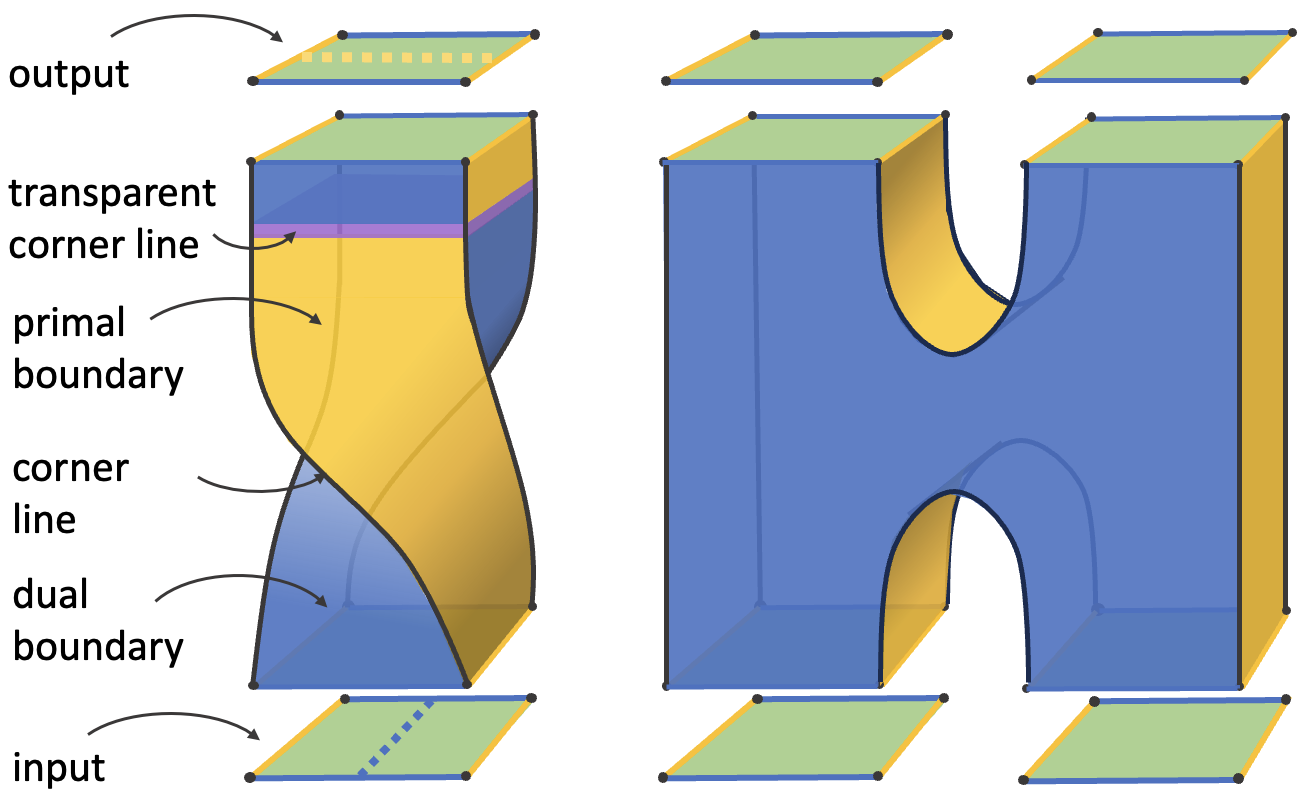
The topological description of surface codes in turn leads to topological description of the logical operations that can be applied to them that includes approaches such as braiding punctures Raussendorf et al. (2006); Raussendorf and Harrington (2007); Raussendorf et al. (2007); Bombin and Martin-Delgado (2008, 2009); Fowler et al. (2009, 2012), lattice surgery Horsman et al. (2012) and braiding twist defects Bombin (2010); Hastings and Geller (2014). We briefly review some aspects of this topological description of logical operations following the more comprehensive discussion presented in Sec III.B of Ref. Bombin et al. (2021).
A stabilizer channel of surface codes can be viewed as a topological object embedded in (2+1)-D spacetime, consisting of a closed connected 3D region with a number of labeled features which are generalizations of features of 2D surface code patches to 3D; see Fig. 23. The region inside is in the topological phase, while the region outside is in the trivial phase. Roughly speaking, records the history of deformation from to which are the 2D boundaries of at the start and end. The entire boundary of is divided into components, with each component categorized as either a primal boundary surface or a dual boundary surface. Two adjacent boundary surfaces must have different types. A corner line is the intersection line between a primal boundary surface and a dual one. A domain wall is the boundary between two bulk regions of . A domain wall can either terminate in the bulk of the toric code phase where a twist line emerges, or terminate on a corner line. A corner line on the boundary of a domain wall is said to be transparent.
While a patch is a topological object with no specified locations of qubits, we can consider explicit cellulations of it with vertices and plaquettes colored yellow and blue and recover explicit surface codes. For example, such as the distance surface code shown in Fig. 10(a) can be recovered by a particular cellulation of .
A -type (-type) non-trivial logical operator forms a string in that connects two different primal (dual) boundaries or forms a topologically non-trivial primal (dual) loop in . With the presence of domain walls, a string can start as -type from a primal boundary, cross a domain wall becoming -type, and then end at a dual boundary. If the string ends at two boundaries that share a transparent corner line, then the string is considered as a trivial logical operator. The action of a topological channel can be inferred by considering these logical operators.
In Ref. Bombin et al. (2021), a strategy was given to specify code deformation channels via the cellulation of a topological description . In this work we use a less precise method, and use the topological description of the Hadamard and measurement depicted in Fig. 23 to loosely suggest an initial code deformation sequence, which we then analyze and modify in the following sections using the techniques we have presented in this paper.